1987 SUZUKI GRAND VITARA service schedule
[x] Cancel search: service schedulePage 17 of 962

SECTION 1
PERIODIC MAINTENANCE SERVICE
CONTENTS
1-1. MAINTENANCE SCHEDULE..................................
1-2.ENGINE AND EMISSION CONTROL...........................1-5
1-3.CHASSIS AND BODY......................................1-17
1
1-2
1-1
Page 32 of 962

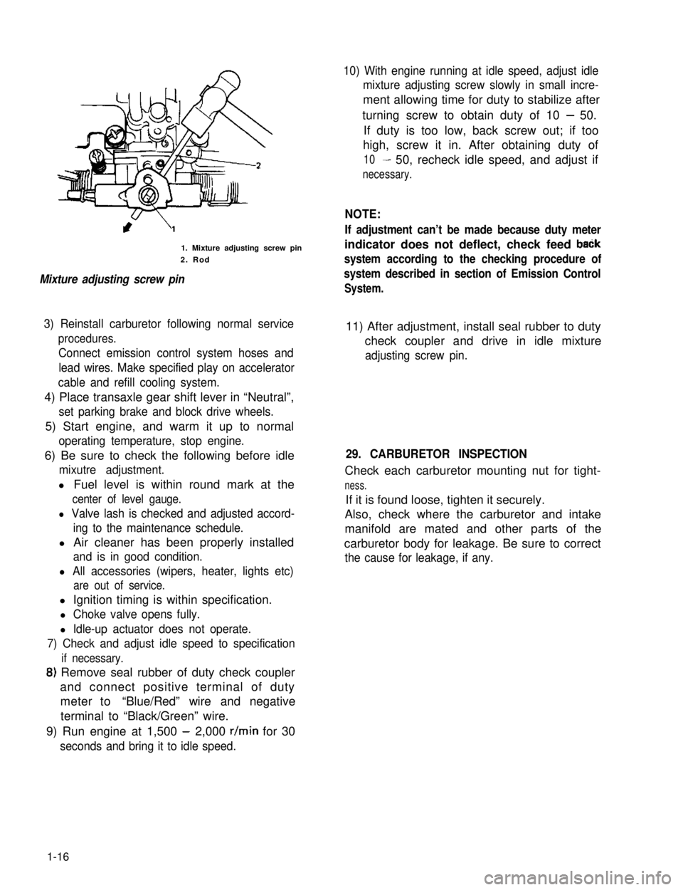
1. Mixture adjusting screw pin
2. Rod
Mixture adjusting screw pin
10) With engine running at idle speed, adjust idle
mixture adjusting screw slowly in small incre-
ment allowing time for duty to stabilize after
turning screw to obtain duty of 10 - 50.
If duty is too low, back screw out; if too
high, screw it in. After obtaining duty of
10- 50, recheck idle speed, and adjust if
necessary.
NOTE:
If adjustment can’t be made because duty meter
indicator does not deflect, check feed baCk
system according to the checking procedure of
system described in section of Emission Control
System.
3) Reinstall carburetor following normal service
procedures.
Connect emission control system hoses and
lead wires. Make specified play on accelerator
cable and refill cooling system.
11) After adjustment, install seal rubber to duty
check coupler and drive in idle mixture
adjusting screw pin.
4) Place transaxle gear shift lever in “Neutral”,
set parking brake and block drive wheels.
5) Start engine, and warm it up to normal
operating temperature, stop engine.
6) Be sure to check the following before idle
mixutre adjustment.
l Fuel level is within round mark at the
center of level gauge.
l Valve lash is checked and adjusted accord-
ing to the maintenance schedule.
l Air cleaner has been properly installed
and is in good condition.
l All accessories (wipers, heater, lights etc)
are out of service.
29. CARBURETOR INSPECTION
Check each carburetor mounting nut for tight-
ness.
If it is found loose, tighten it securely.
Also, check where the carburetor and intake
manifold are mated and other parts of the
carburetor body for leakage. Be sure to correct
the cause for leakage, if any.
l Ignition timing is within specification.
l Choke valve opens fully.
l Idle-up actuator does not operate.
7) Check and adjust idle speed to specification
if necessary.
8) Remove seal rubber of duty check coupler
and connect positive terminal of duty
meter to“Blue/Red” wire and negative
terminal to “Black/Green” wire.
9) Run engine at 1,500 - 2,000 r/min for 30
seconds and bring it to idle speed.
1-16
Page 141 of 962

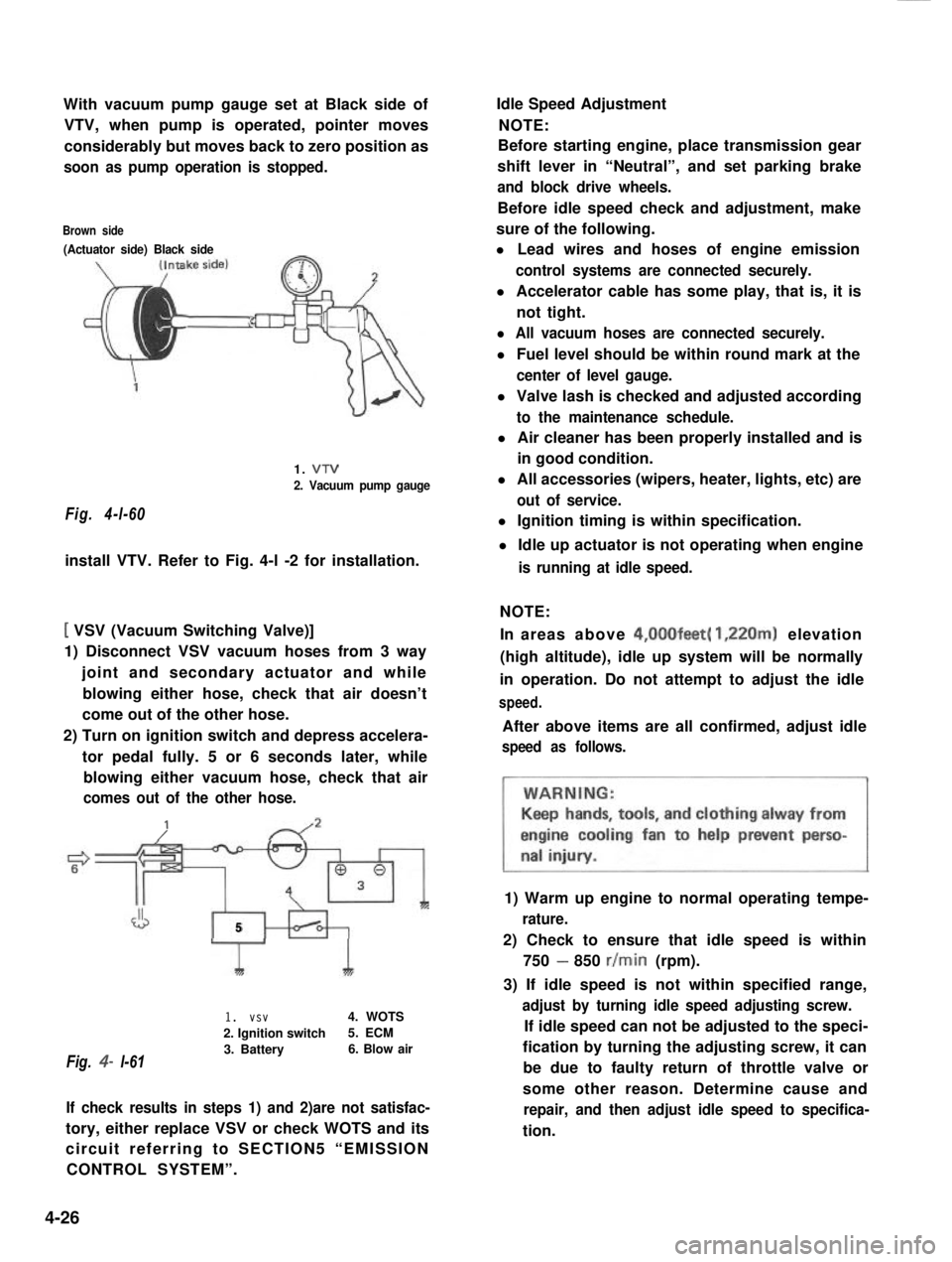
With vacuum pump gauge set at Black side of
VTV, when pump is operated, pointer moves
considerably but moves back to zero position as
soon as pump operation is stopped.
Brown side
(Actuator side) Black side
Fig. 4-l-60
1. VTV
2. Vacuum pump gauge
install VTV. Refer to Fig. 4-l -2 for installation.
[ VSV (Vacuum Switching Valve)]
1) Disconnect VSV vacuum hoses from 3 way
joint and secondary actuator and while
blowing either hose, check that air doesn’t
come out of the other hose.
2) Turn on ignition switch and depress accelera-
tor pedal fully. 5 or 6 seconds later, while
blowing either vacuum hose, check that air
comes out of the other hose.
J5
Fig. 4- l-61
1I
1. vsv4. WOTS
2. Ignition switch5. ECM
3. Battery6. Blow air
If check results in steps 1) and 2)are not satisfac-
tory, either replace VSV or check WOTS and its
circuit referring to SECTION5 “EMISSION
CONTROL SYSTEM”.
Idle Speed Adjustment
NOTE:
Before starting engine, place transmission gear
shift lever in “Neutral”, and set parking brake
and block drive wheels.
Before idle speed check and adjustment, make
sure of the following.
l Lead wires and hoses of engine emission
control systems are connected securely.
l Accelerator cable has some play, that is, it is
not tight.
l All vacuum hoses are connected securely.
l Fuel level should be within round mark at the
center of level gauge.
l Valve lash is checked and adjusted according
to the maintenance schedule.
l Air cleaner has been properly installed and is
in good condition.
l All accessories (wipers, heater, lights, etc) are
out of service.
l Ignition timing is within specification.
l Idle up actuator is not operating when engine
is running at idle speed.
NOTE:
In areas above 4,00Ofeet( 1,220m) elevation
(high altitude), idle up system will be normally
in operation. Do not attempt to adjust the idle
speed.
After above items are all confirmed, adjust idle
speed as follows.
1) Warm up engine to normal operating tempe-
rature.
2) Check to ensure that idle speed is within
750 - 850 r/min (rpm).
3) If idle speed is not within specified range,
adjust by turning idle speed adjusting screw.
If idle speed can not be adjusted to the speci-
fication by turning the adjusting screw, it can
be due to faulty return of throttle valve or
some other reason. Determine cause and
repair, and then adjust idle speed to specifica-
tion.
4-26
Page 143 of 962

3) Reinstall carburetor following normal service
procedures.
Connect emission control system hoses and
lead wires. Make specified play on accelerator
cable and refill cooling system.
4) Place transaxle gear shift lever in “Neutral”,
set parking brake and block drive wheels.
5) Start engine, and warm it up to normal
operating temperature, stop engine.
6) Be sure to check the following before idle
mixture adjustment.
l Fuel level is within round mark at the
center of level gauge.
l Valve lash is checked and adjusted accord-
ing to the maintenance schedule.
l Air cleaner has been properly installed
and is in good condition.
l All accessories (wipers, heater, lights etc)
are out of service.
l Ignition timing is within specification.
l Choke valve opens fully.
l Idle-up actuator does not operate.
7) Check and adjust idle speed to specification
if necessary.
8) Remove seal rubber of duty check coupler
and connect positive terminal of duty
meter to“Blue/Red” wire and negative
terminal to “Black/Green” wire.
9) Run engine at 1,500 - 2,000 r/min for 30
seconds and bring it to idle speed.
10) With engine running at idle speed, adjust idle
mixture adjusting screw slowly in small incre-
ment allowing time for duty to stabilize after
turning screw to obtain duty of 10 - 50.
If duty is too low, back screw out; if too
high, screw it in. After obtaining duty of
10 - 50, recheck idle speed, and adjust if
necessary.
NOTE:
If adjustment can’t be made because duty meter
indicator does not deflect, check feed back
system according to the checking procedure of
system described in section of Emission Control
System.
11) After adjustment, install seal rubber to duty
check coupler and drive in idle mixture
adjusting screw pin.
4-28
Page 314 of 962

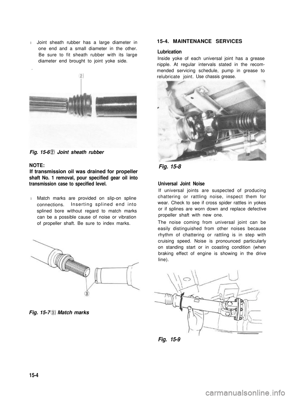
l Joint sheath rubber has a large diameter in
one end and a small diameter in the other.
Be sure to fit sheath rubber with its large
diameter end brought to joint yoke side.
.
cc
Fig. 15-6 @I Joint sheath rubber
NOTE:
If transmission oil was drained for propeller
shaft No. 1 removal, pour specified gear oil into
transmission case to specified level.
l Match marks are provided on slip-on spline
connections.Inserting splined end into
splined bore without regard to match marks
can be a possible cause of noise or vibration
of propeller shaft. Be sure to index marks.
Fig. 15-7 @I Match marks
15-4. MAINTENANCE SERVICES
Lubrication
Inside yoke of each universal joint has a grease
nipple. At regular intervals stated in the recom-
mended servicing schedule, pump in grease to
relubricate joint.Use chassis grease.
Fig. 15-8
Universal Joint Noise
If universal joints are suspected of producing
chattering or rattling noise, inspect them for
wear. Check to see if cross spider rattles in yokes
or if splines are worn down and replace defective
propeller shaft with new one.
The noise coming from universal joint can be
easily distinguished from other noises because
rhythm of chattering or rattling is in step with
cruising speed. Noise is pronounced particularly
on standing start or in coasting condition (when
braking effect of engine is showing in the drive
line).
Fig. 15-9
15-4