1987 SUZUKI GRAND VITARA oil temperature
[x] Cancel search: oil temperaturePage 23 of 962
NOTE:
Steps 1) - 6) outlined above must be performed
with ENGINE NOT RUNNING. For step 7),
be sure to have adequate ventilation while
engine is running
It is recommended to use engine oil of SE or
SF class.
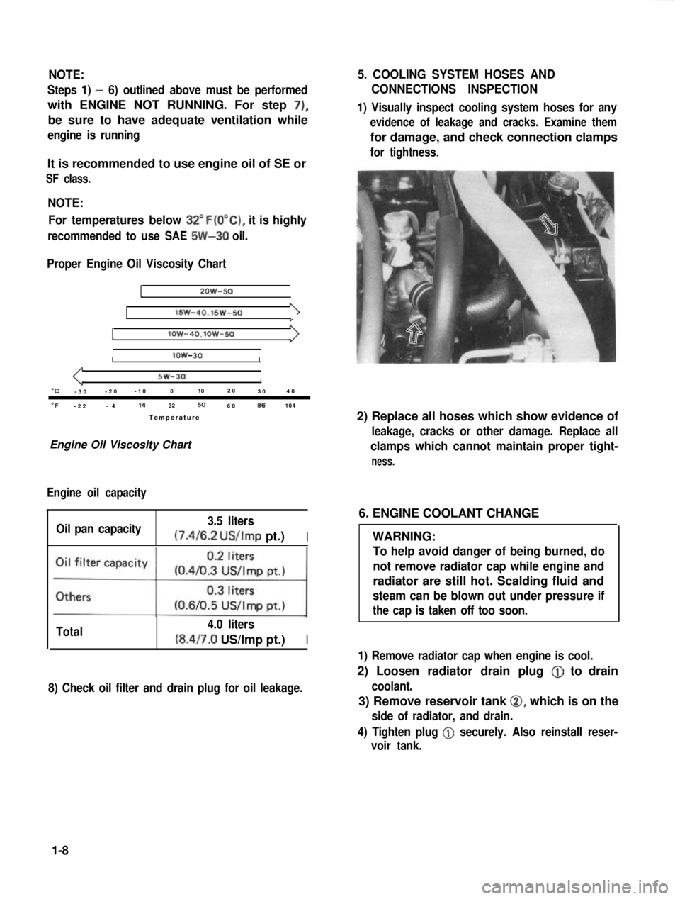
NOTE:For temperatures below
32”F(O”C), it is highly
recommended to use SAE 5W-30 oil.
Proper Engine Oil Viscosity Chart
12OW-50
lSW-40.15w-501
Ilow-4O.lOW-50
Ilow-30I
5w-30I“C-3 0 -2
0 -1
0 0 102
0
30 4
0
OF-2 2 -
4 14
32506886104
Temperatur e
Engine Oil Viscosity Chart
Engine oil capacity
Oil pan capacity 3.5 liters (7.4/6.2
US/Imp pt.)I
Total 4.0 liters(8.4/7.0 US/Imp pt.)I
8) Check oil filter and drain plug for oil leakage.
5. COOLING SYSTEM HOSES AND
CONNECTIONS INSPECTION
1) Visually inspect cooling system hoses for any
evidence of leakage and cracks. Examine them
for damage, and check connection clamps
for tightness.
2) Replace all hoses which show evidence of
leakage, cracks or other damage. Replace all
clamps which cannot maintain proper tight-
ness.
6. ENGINE COOLANT CHANGE
WARNING:
To help avoid danger of being burned, do
not remove radiator cap while engine and
radiator are still hot. Scalding fluid and
steam can be blown out under pressure if
the cap is taken off too soon.
1) Remove radiator cap when engine is cool.
2) Loosen radiator drain plug @
to drain
coolant.
3) Remove reservoir tank 0, which is on the
side of radiator, and drain.
4) Tighten plug
@ securely. Also reinstall reser-
voir tank.
1-8
Page 36 of 962
3) Check propeller shaft (No. 1, No. 2, No. 3)
flange yoke bolts for tightness, and retighten
them as necessary:
N.mkg-mlb-ftTighteningtorque23-302.3-3.017.0-21.5
42. TRANSMISSION, TRANSFER,
DIFFERENTIAL OIL INSPECTION
AND CHANGE
[I nspectionl
1) Inspect transmission case, transfer case and
differential housing for evidence of oil leakage.
Repair leaky point if any.
2) Make sure that the car is placed level for oil
level check.
3) Remove each level plug of transmission,
transfer and differential (front and rear).
In any of these cases, oil level can be checked
roughly by means of level plug hole. That is,
,if oil flows out of level plug hole or if oil
level is found up to hole when level plug is
removed, oil is properly filled.
If oil is found insufficient, pour specified
amount of specified oil as given in the below
table.
[Change]
Oil change procedure is as follows.
Place the car level and drain oil by removing
drain plug. Pour specified amount of specified
oil as in the below table and tighten drain plug
and filler plug to specified torque.
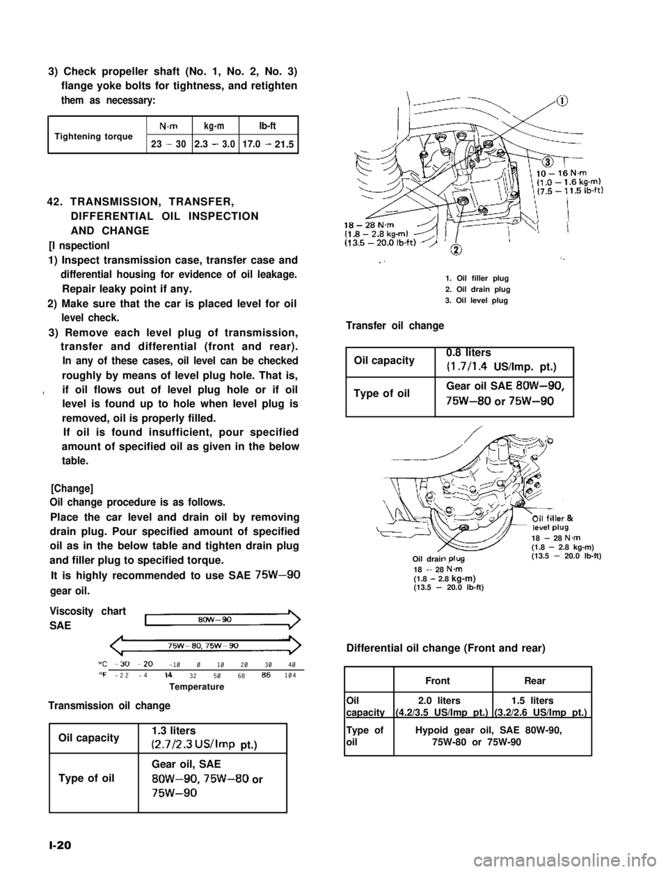
It is highly recommended to use SAE 75W-90
gear oil.
Viscosity chart
SAE
75w-ao,75w-90
"C -30 --20 -10 0 10 20 30 40"F -22 -4lb 32 50 68 86104
Temperature
Transmission oil change
Oil capacity
Type of oil
1.3 liters
(2.7/2.3 US/Imp pt.)
Gear oil, SAE
8OW-90,75W-80 or
75w-90
l-20
18-28N.m
I ”’
1. Oil filler plug
2. Oil drain plug
3. Oil level plug
Transfer oil change
Oil capacity0.8 liters
(1.7/l .4 US/Imp. pt.)
Type of oilGear oil SAE 8OW-90,
75W-80 or 75W-90
18 - 28 N.m(1.8 - 2.8 kg-m)(13.5 - 20.0 lb-ft)-R-Oil drair18 - 28 N&(1.8 - 2.8 kg-m)(13.5 - 20.0 lb-ft)
Differential oil change (Front and rear)
1.5 liters
(3.2/2.6 US/Imp pt.)
2.0 liters
(4.2/3.5 US/Imp pt.)
FrontRear
Oil
capacity
Type of
oil
Hypoid gear oil, SAE 80W-90,
75W-80 or 75W-90
Page 46 of 962

ConditionPossible causeCorrection
High fuel consumptionAbnormal condition ignition system
1. Improper ignition timingAdjust
2. Leak or loose connection of high tension cordRepair or replace
3. Defective spark plug (improper gap, heavyClean, adjust or replace
deposits, and burned electrodes, etc..)
4. Cracked distributor cap or rotorReplace
5. Malfunctioning mechanical and vacuumCheck and repair or
advancers in distributorreplace
Abnormal condition in fuel system
1. Improper float levelAdjust
2. Fuel leakage from tank, pipe or carburetorRepair or replace
3. Malfunctioning carburetor choke systemRepair or replace
4. Dirty or clogged carburetor jetsClean
5. Clogged air cleaner elementClean or replace
6. Malfunctioning thermostatically controlledCheck and repair or
air cleanerreplace
Abnormal condition in engine
1. Low compressionPreviously outlined
2. Poor valve seatingRepair or replace
3. Improper valve clearanceAdjust
Emission control
1. Air leaks at exhaust manifoldTighten manifold bolts
and nuts.
Replace gasket.
2. Oxygen sensor out of orderReplace.
3. Water temperature switch out of orderReplace.
4. Malfunctioning throttle position switchReplace
5. Malfunctioning MCS (mixture controlReplace
solenoid) valve in carburetor
6. Malfunctioning EGR valveReplace
Others
1. Dragging brakesRepair or replace
2. Slipping clutchAdjust or replace
3. Improper tire pressureAdjust
Excessive engine oilOil leakage
consumption1. Loose oil drain plugTighten
2. Loose oil pan securing boltsTighten
3. Deteriorated or broken oil pan sealantReplace sealant
4. Leaky oil sealsReplace
5. Blown cylinder head gasketReplace
6. Improper tightening of oil filterTighten
7. Loose oil pressure switchTighten
2-8
Page 57 of 962

2-14. SPEEDOMETER
IConditionIPossible causeICorrection
Faulty indication1. Damaged speedometer drive or driven gear
2. Defective drive cable
3. Drive cable incompletely or imporperly
tied into the meter
4. Defective speedometer
Replace
Replace
Set right
Replace
Speedometer noise1. Inadequately lubricated or defective cable
2. Not enough oil in transfer
Lubricate or replace
Replenish
2-15. WATER TEMPERATURE METER
Condition
Faulty indication
No indication
Possible cause
1. Incomplete metal-to-metal contact in
terminal connections
2. Receiver gauge defective (due to burnt
point or deformed bimetal element)
3. Defective temperature gauge
1. Open-circuit
2. Defective receiver gauge (open-circuited
heat wire, deformed bimetal element or
pointer)
Repair
Replace
3. Defective temperature gaugeReplace
Correction
Repair and tighten
Replace
Replace
2-19
Page 83 of 962
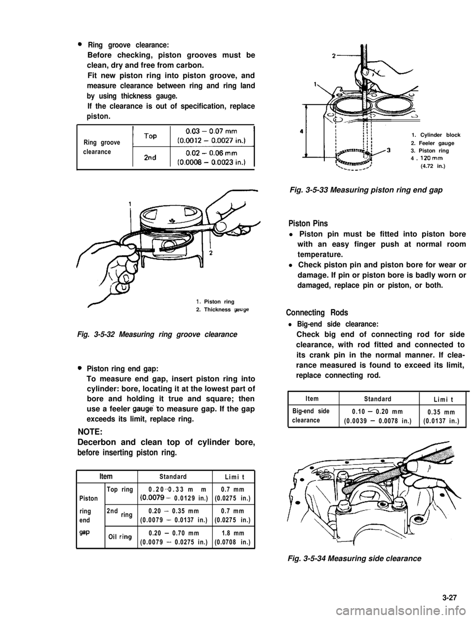
0Ring groove clearance:
Before checking, piston grooves must be
clean, dry and free from carbon.
Fit new piston ring into piston groove, and
measure clearance between ring and ring land
by using thickness gauge.
If the clearance is out of specification, replace
piston.
Ring groove
clearanceti1
1. Piston ring
2. Thickness geuge
Fig. 3-5-32 Measuring ring groove clearance
0Piston ring end gap:
To measure end gap, insert piston ring into
cylinder: bore, locating it at the lowest part of
bore and holding it true and square; then
use a feeler gauge’to measure gap. If the gap
exceeds its limit, replace ring.
NOTE:
Decerbon and clean top of cylinder bore,
before inserting piston ring.
ItemStandardLimit
Top ring0.20 0.33 mm-0.7 mm
Piston(0.0079 - 0.0129in.)(0.0275 in.)
ring2ndring0.20 - 0.35 mm0.7 mm
end(0.0079 - 0.0137 in.)(0.0275 in.)
QaPOil riilg0.20 - 0.70 mm1.8 mm
(0.0079 - 0.0275 in.)(0.0708 in.)
1. Cylinder block
2. Feeler gauge3. Piston ring4. 12Omm(4.72 in.)
Fig. 3-5-33 Measuring piston ring end gap
Piston Pins
l Piston pin must be fitted into piston bore
with an easy finger push at normal room
temperature.
l Check piston pin and piston bore for wear or
damage. If pin or piston bore is badly worn or
damaged, replace pin or piston, or both.
Connecting Rods
l Big-end side clearance:
Check big end of connecting rod for side
clearance, with rod fitted and connected to
its crank pin in the normal manner. If clea-
rance measured is found to exceed its limit,
replace connecting rod.
Item
Big-end side
clearance
StandardLimit
0.10 - 0.20 mm0.35 mm
(0.0039 - 0.0078 in.)(0.0137 in.)
Fig. 3-5-34 Measuring side clearance
3-27
Page 113 of 962
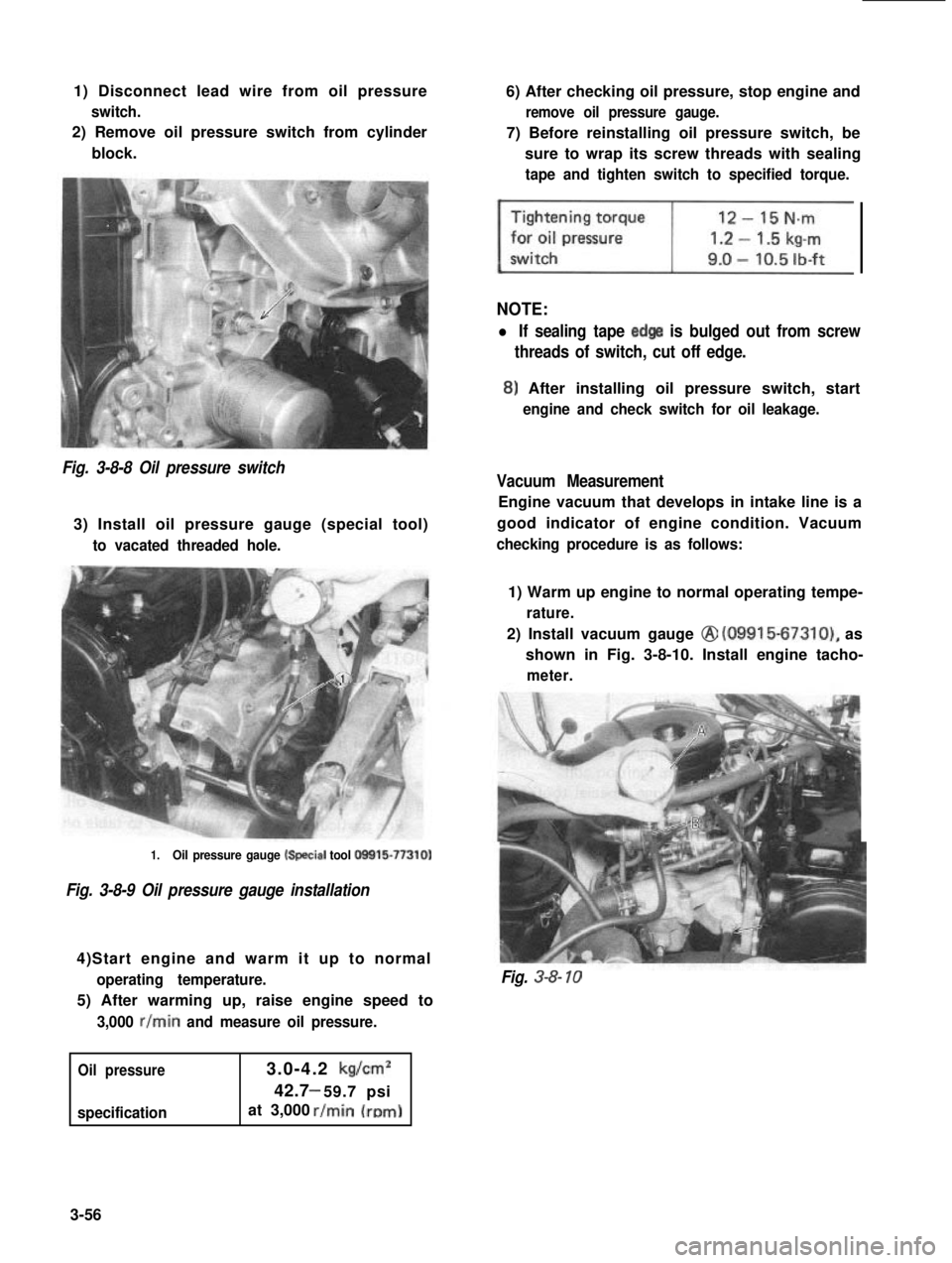
1) Disconnect lead wire from oil pressure
switch.
2) Remove oil pressure switch from cylinder
block.
6) After checking oil pressure, stop engine and
remove oil pressure gauge.
7) Before reinstalling oil pressure switch, be
sure to wrap its screw threads with sealing
tape and tighten switch to specified torque.
NOTE:
l If sealing tape edge is bulged out from screw
threads of switch, cut off edge.
8) After installing oil pressure switch, start
engine and check switch for oil leakage.
Fig. 3-8-8 Oil pressure switch
3) Install oil pressure gauge (special tool)
to vacated threaded hole.
Vacuum Measurement
Engine vacuum that develops in intake line is a
good indicator of engine condition. Vacuum
checking procedure is as follows:
1.Oil pressure gauge k+ecial tool O!Xil5-77310)
Fig. 3-8-9 Oil pressure gauge installation
4)Start engine and warm it up to normal
operating temperature.
5) After warming up, raise engine speed to
3,000 r/min and measure oil pressure.
Oil pressure
specification
3.0-4.2 kg/cm2
42.7 59.7 psi-
at 3,000
1) Warm up engine to normal operating tempe-
rature.
2) Install vacuum gauge @ (09915-67310), as
shown in Fig. 3-8-10. Install engine tacho-
meter.
Fig. 3-8- 10
3-56
Page 164 of 962
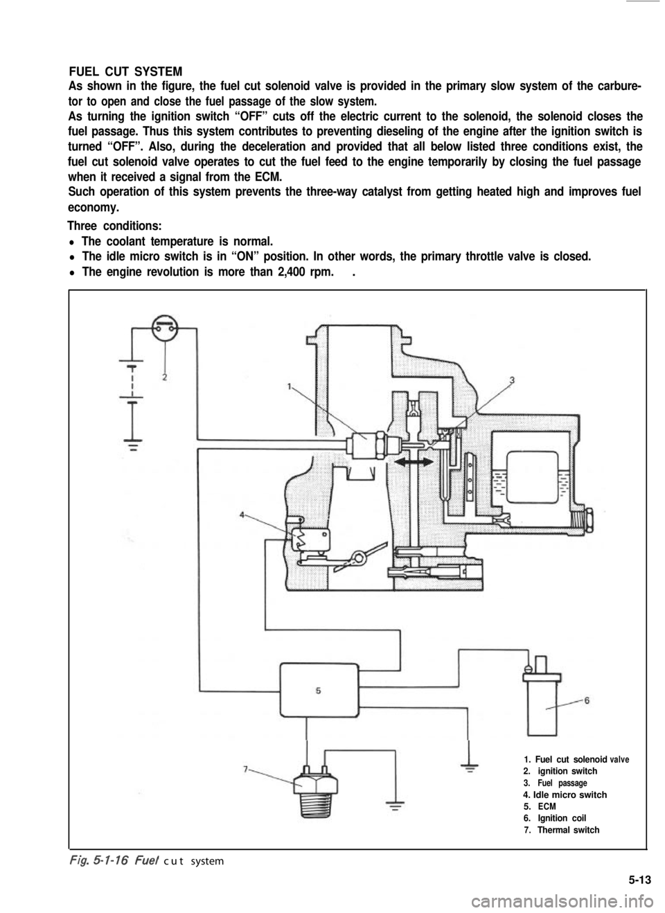
FUEL CUT SYSTEM
As shown in the figure, the fuel cut solenoid valve is provided in the primary slow system of the carbure-
tor to open and close the fuel passage of the slow system.
As turning the ignition switch “OFF” cuts off the electric current to the solenoid, the solenoid closes the
fuel passage. Thus this system contributes to preventing dieseling of the engine after the ignition switch is
turned “OFF”. Also, during the deceleration and provided that all below listed three conditions exist, the
fuel cut solenoid valve operates to cut the fuel feed to the engine temporarily by closing the fuel passage
when it received a signal from the ECM.
Such operation of this system prevents the three-way catalyst from getting heated high and improves fuel
economy.
Three conditions:
l The coolant temperature is normal.
l The idle micro switch is in “ON” position. In other words, the primary throttle valve is closed.
l The engine revolution is more than 2,400 rpm..
1. Fuel cut solenoid
2.ignition switch
3.Fuel passage
4. Idle micro switch
5.ECM
6.Ignition coil
7.Thermal switch
valve
-. .t/g. cut system
5-13
Page 193 of 962
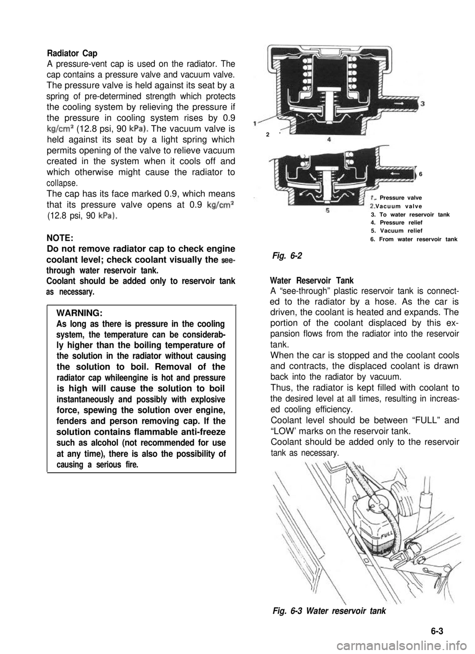
Radiator Cap
A pressure-vent cap is used on the radiator. The
cap contains a pressure valve and vacuum valve.
The pressure valve is held against its seat by a
spring of pre-determined strength which protects
the cooling system by relieving the pressure if
the pressure in cooling system rises by 0.9
kg/cm2 (12.8 psi, 90 kPa). The vacuum valve is
held against its seat by a light spring which
permits opening of the valve to relieve vacuum
created in the system when it cools off and
which otherwise might cause the radiator to
collapse.
The cap has its face marked 0.9, which means
that its pressure valve opens at 0.9 kg/cm2
(12.8 psi, 90 kPa).
NOTE:
Do not remove radiator cap to check engine
coolant level; check coolant visually the see-
through water reservoir tank.
Coolant should be added only to reservoir tank
as necessary.
4
WARNING:
As long as there is pressure in the cooling
system, the temperature can be considerab-
ly higher than the boiling temperature of
the solution in the radiator without causing
the solution to boil. Removal of the
radiator cap whileengine is hot and pressure
is high will cause the solution to boil
instantaneously and possibly with explosive
force, spewing the solution over engine,
fenders and person removing cap. If the
solution contains flammable anti-freeze
such as alcohol (not recommended for use
at any time), there is also the possibility of
causing a serious fire.
2’
I6
. Pressure valve
Vacuum valve
3. To water reservoir tank4. Pressure relief5. Vacuum relief
6. From water reservoir tank
Fig. 6-2
Water Reservoir Tank
A “see-through” plastic reservoir tank is connect-
ed to the radiator by a hose. As the car is
driven, the coolant is heated and expands. The
portion of the coolant displaced by this ex-
pansion flows from the radiator into the reservoir
tank.
When the car is stopped and the coolant cools
and contracts, the displaced coolant is drawn
back into the radiator by vacuum.
Thus, the radiator is kept filled with coolant to
the desired level at all times, resulting in increas-
ed cooling efficiency.
Coolant level should be between “FULL” and
“LOW’ marks on the reservoir tank.
Coolant should be added only to the reservoir
tank as necessary.
Fig. 6-3 Water reservoir tank
6-3