1987 SUZUKI GRAND VITARA heater
[x] Cancel search: heaterPage 2 of 962

TABLE OF CONTENTS
GENERAL, SPECIAL TOOLS AND SERVICE MATERIALS
PERIODIC MAINTENANCE SERVICE
TROUBLE SHOOTING
ENGINE
FUEL SYSTEM (CARBURETOR, AIR CLEANER FUEL PUMP AND FUEL FILTER)
EMISSION CONTROL SYSTEM
ENGINE COOLING SYSTEM
CAR HEATER
IGNITION SYSTEM
CRANKING SYSTEM
CHARGING SYSTEM
CLUTCH
GEAR SHIFTING CONTROL
TRANSMISSION
TRANSFER GEAR BOX
PROPELLER SHAFTS
DIFFERENTIAL
SUSPENSION
STEERING SYSTEM
BRAKES
BODY SERVICE
,i BODY ELECTRICAL EQUIPMENT
SERVICE DATA
0
1
2
5
6
7
8
9
10
1111
12
13
14
15
16
17
18
19
20
21
22
4
3
SECTION
Page 25 of 962
CAUTION:
When changing engine coolant, use mixture
of 56% water and 50% GOLDEN CRUISER
1200for the market where ambient tem-
perature falls lower than -16°C (3°F) in
winter and mixture of 70% water and
30% GOLDEN CRUISER 1200for the
market where ambient temperature doesn’t
fall lower than -16°C (3” F).
Even in a market where no freezing tempe-
rature is anticipated, mixture of 70% water
and 30% GOLDEN CRUISER 1200
should be used for the purpose of corro-
sion protection and lubrication.
7. EXHAUST PIPES AND MOUNTINGS
INSPECTION
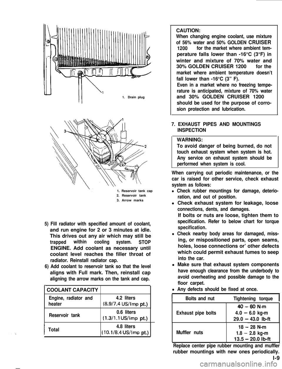
1.Drain plug
1. Reservoir tank cap2. Reservoir tank
3. Arrow marks
5) Fill radiator with specified amount of coolant,
and run engine for 2 or 3 minutes at idle.
This drives out any air which may still be
trappedwithincoolingsystem.STOP
ENGINE. Add coolant as necessary until
coolant level reaches the filler throat of
radiator. Reinstall radiator cap.
6) Add coolant to reservoir tank so that the level
aligns with Full mark. Then, reinstall cap
aligning the arrow marks on the tank and cap.
r.
COOLANT CAPACITY
Engine, radiator and4.2 liters
heater(8.9/7.4 US/Imp pt.)
Reservoir tank0.6 liters
(1.3/1.1 US/Imp pt.)
ITotal4.8 liters
(10.1/8.4US/lmp pt.)
WARNING:
To avoid danger of being burned, do not
touch exhaust system when system is hot.
Any service on exhaust system should be
performed when system is cool.
When carrying out periodic maintenance, or the
car is raised for other service, check exhaust
system as follows:
l Check rubber mountings for damage, deterio-
ration, and out of position.
l Check exhaust system for leakage, loose
connections, dents, and damages.
If bolts or nuts are loose, tighten them to
specification. Refer to below chart for torque
specification.
l Check nearby body areas for damaged, miss-
ing, or mispositioned parts, open seams,
holes, loose connections or’ other defects
which could permit exhaust fumes to seep
into the car.
l Make sure that exhaust system components
have enough clearance from the underbody to
avoid overheating and possible damage to the
floor carpet.
l Any defects should be fixed at once.
IBolts and nutTightening torqueI
40-80 N-m
Exhaustpipebolts4.0-6.0 kg-m
29.0-43.0 lb-ft
Muffler nuts
18 - 28 N-m
1.8 - 2.8 kg-m
13.5 - 20.0 lb-ft
Replace center pipe rubber mounting and muffler
rubber mountings with new ones periodically.
l-9
Page 26 of 962
8. PCV VALVE REPLACEMENT
1) Disconnect crankcase ventilation hose from
PCV valve.
2) Remove PCV valve from intake manifold.
3) Wind sealing tape on thread of the new valve
and install it securely.
Tightenlng torque
for PCV valve
15-25 N.m
1.5-2.5 kg-m,
11 .O-18.0 lb-ft
4) Install hose and clamp it securely.
9. OXYGEN SENSOR REPLACEMENT
[Canadian specification vehicle]
When the odometer indicates 50,000 and 100,000
miles, replace oxygen sensor as follows.
CAUTION:
To avoid the danger of being burned, do
not touch the exhaust system when the
system is hot. This work should be perform-
ed when the system is cool.
1) Disconnect battery negative cable from
battery and disconnect oxygen sensor wire at
the coupler.
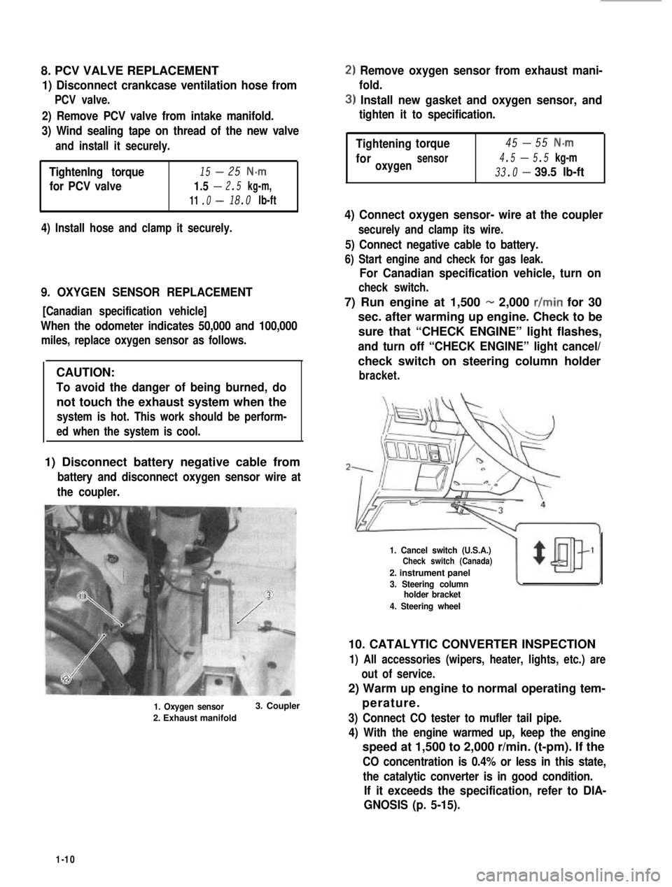
1. Oxygen sensor
2. Exhaust manifold
3. Coupler
2) Remove oxygen sensor from exhaust mani-
fold.
3) Install new gasket and oxygen sensor, and
tighten it to specification.
-Tightening45torque55 N-m
4.5-foroxygensensor5.5 kg-m
33.0-39.5 lb-ft
4) Connect oxygen sensor- wire at the coupler
securely and clamp its wire.
5) Connect negative cable to battery.
6) Start engine and check for gas leak.
For Canadian specification vehicle, turn on
check switch.
7) Run engine at 1,500 - 2,000 r/min for 30
sec. after warming up engine. Check to be
sure that “CHECK ENGINE” light flashes,
and turn off “CHECK ENGINE” light cancel/
check switch on steering column holder
bracket.
1. Cancel switch (U.S.A.)Check switch (Canada)
2. instrument panel
3. Steering columnholder bracket
4. Steering wheel
10. CATALYTIC CONVERTER INSPECTION
1) All accessories (wipers, heater, lights, etc.) are
out of service.
2) Warm up engine to normal operating tem-
perature.
3) Connect CO tester to mufler tail pipe.
4) With the engine warmed up, keep the engine
speed at 1,500 to 2,000 r/min. (t-pm). If the
CO concentration is 0.4% or less in this state,
the catalytic converter is in good condition.
If it exceeds the specification, refer to DIA-
GNOSIS (p. 5-15).
1-10
Page 32 of 962
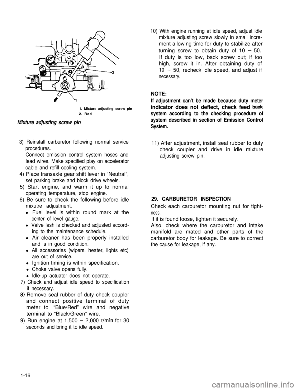
1. Mixture adjusting screw pin
2. Rod
Mixture adjusting screw pin
10) With engine running at idle speed, adjust idle
mixture adjusting screw slowly in small incre-
ment allowing time for duty to stabilize after
turning screw to obtain duty of 10 - 50.
If duty is too low, back screw out; if too
high, screw it in. After obtaining duty of
10- 50, recheck idle speed, and adjust if
necessary.
NOTE:
If adjustment can’t be made because duty meter
indicator does not deflect, check feed baCk
system according to the checking procedure of
system described in section of Emission Control
System.
3) Reinstall carburetor following normal service
procedures.
Connect emission control system hoses and
lead wires. Make specified play on accelerator
cable and refill cooling system.
11) After adjustment, install seal rubber to duty
check coupler and drive in idle mixture
adjusting screw pin.
4) Place transaxle gear shift lever in “Neutral”,
set parking brake and block drive wheels.
5) Start engine, and warm it up to normal
operating temperature, stop engine.
6) Be sure to check the following before idle
mixutre adjustment.
l Fuel level is within round mark at the
center of level gauge.
l Valve lash is checked and adjusted accord-
ing to the maintenance schedule.
l Air cleaner has been properly installed
and is in good condition.
l All accessories (wipers, heater, lights etc)
are out of service.
29. CARBURETOR INSPECTION
Check each carburetor mounting nut for tight-
ness.
If it is found loose, tighten it securely.
Also, check where the carburetor and intake
manifold are mated and other parts of the
carburetor body for leakage. Be sure to correct
the cause for leakage, if any.
l Ignition timing is within specification.
l Choke valve opens fully.
l Idle-up actuator does not operate.
7) Check and adjust idle speed to specification
if necessary.
8) Remove seal rubber of duty check coupler
and connect positive terminal of duty
meter to“Blue/Red” wire and negative
terminal to “Black/Green” wire.
9) Run engine at 1,500 - 2,000 r/min for 30
seconds and bring it to idle speed.
1-16
Page 63 of 962
3-3. ENGINE REMOVAL
1) Disconnect negative (-) and positive (+)
cords from battery terminals.
‘)From starter motor terminals, disconnect
black/yellow lead wire and positive (+)
battery cord.
Disconnect coupler and white lead wire
from alternator terminals.
Disconnect lead wires from water tempera-
ture gauge and thermal switch. The gauge
and switch are on intake manifold.
Disconnect earth lead wire from intake
manifold.
5) Disconnect couplers of carburetor fuel cut
solenoid valve, vent solenoid valve and
mixture control solenoid valve, and dis-
connect couplers from TWSVS and VSV.
6) Remove warm air hose.
) Disconnect breather hose from air cleaner
case.
,) Remove air intake case from carburetor
body and air inlet hose.
1) Disconnect accelerator cable from carbure-
tor.
10) Disconnect vacuum hoses of TCAC and
canister from intake manifold.
11) Remove fuel tank filler cap to release fuel
vapor pressure in fuel tank. After releasing,
reinstall it. Disconnect fuel feed and return
hoses from fuel pump.
12) Disconnect lead wire from oil pressure unit
terminal and oxygen sensor lead wire at the
coupler.
13) Disconnect lead wires of back-up light
switch and fifth switch at their couplers.
14) Disconnect distributor lead wire at the
coupler.
15) Pull off high-tension cord from ignition coil.
16) Loosen radiator drain plug to drain cooling
water,
17) Disconnect water hoses from thermostat
cap and water inlet pipe. After removing
cooling fan & clutch and fan shroud, remove
radiator.
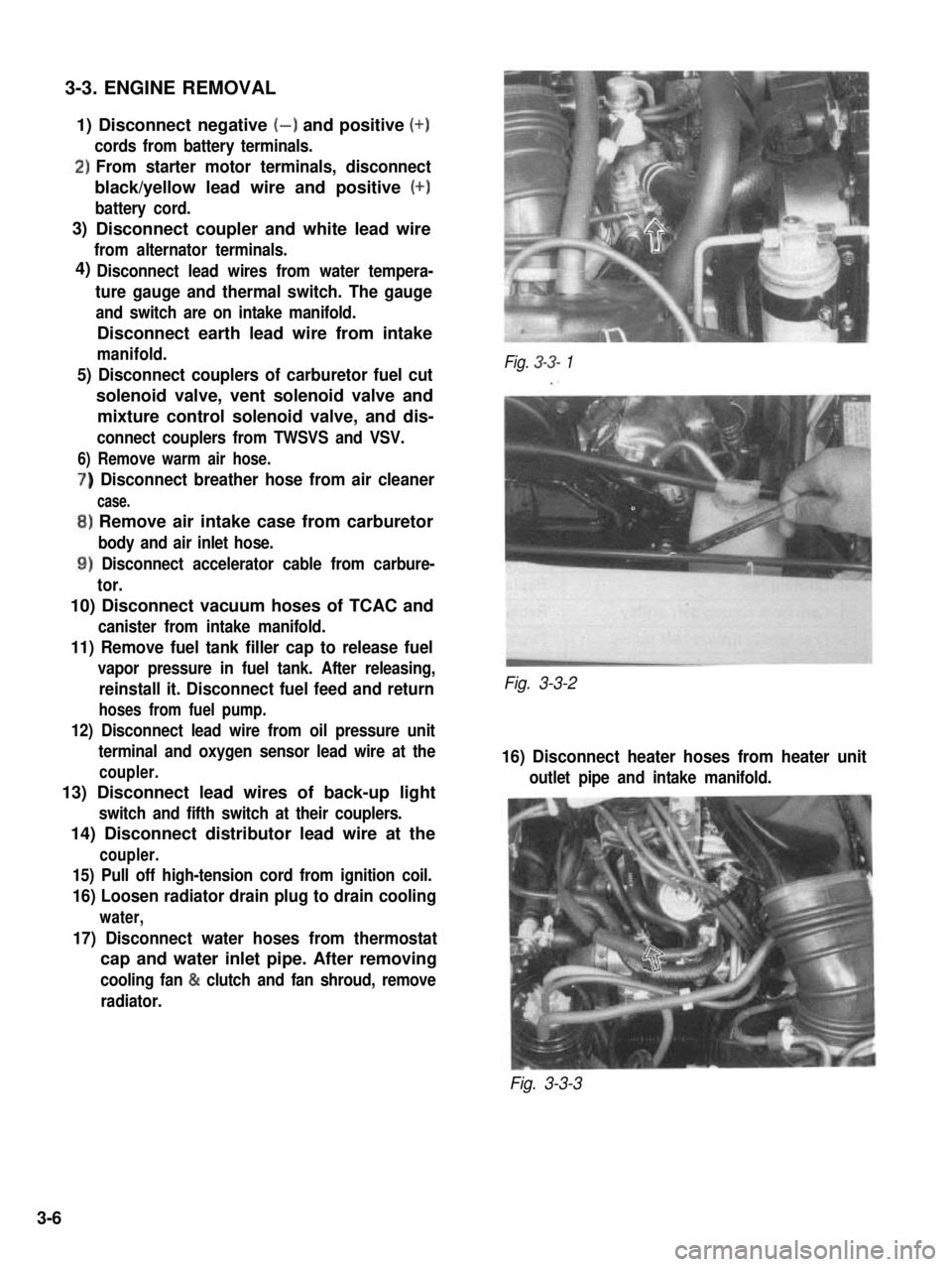
Fig. 3-3- 1
Fig. 3-3-2
16) Disconnect heater hoses from heater unit
outlet pipe and intake manifold.
Fig. 3-3-3
3)
4)
3-6
Page 126 of 962
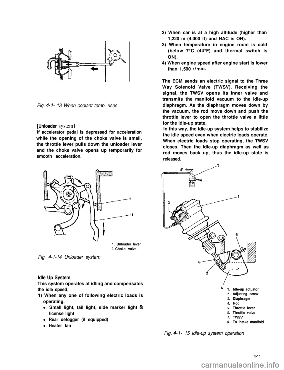
Fig. 4- l- 13 When coolant temp. rises
[Unloader system1
If accelerator pedal is depressed for acceleration
while the opening of the choke valve is small,
the throttle lever pulls down the unloader lever
and the choke valve opens up temporarily for
smooth acceleration.
1. Unloader lever
2. Choke valve
Fig. 4-1-14 Unloader system
Idle Up System
This system operates at idling and compensates
the idle speed;
1) When any one of following electric loads is
operating.
l Small light, tail light, side marker light &
license light
l Rear defogger (if equipped)
l Heater fan
2) When car is at a high altitude (higher than
1,220 m (4,000 ft) and HAC is ON).
3) When temperature in engine room is cold
(below 7°C (44°F) and thermal switch is
ON).
4) When engine speed after engine start is lower
than 1,500 r/min.
The ECM sends an electric signal to the Three
Way Solenoid Valve (TWSV). Receiving the
signal, the TWSV opens its inner valve and
transmits the manifold vacuum to the idle-up
diaphragm. As the diaphragm moves down by
the vacuum, the rod move down and push the
throttle lever to open the throttle valve a little
for the idle-up state.
In this way, the idle-up system helps to stabilize
the idle speed even when electric loads operate.
When electric loads stop operating, the TWSV
closes. Then the idle-up diaphragm as well as
rod moves back up, thus the idle-up state is
released.
I
5 1.
2.
3.
4.5.
8.
7.
8.
Idle-up actuatorAdjusting screw
Diaphragm
Rod
Throttle lever
Throttle valve
Twsv
To intake manifold
Fig. 4- I- 15 Idle-up system operation
4-11
Page 136 of 962
4) With lights (head light) turned “ON”, check
engine rpm (idle-up speed). Be sure that
heater fan, rear defogger (if equipped), and
air conditioner (if equipped) are all turned
“OFF”.
Idle-up speed900 - 1,000 r/min.
If idle-up speed is not within specification,
adjust by turning adjusting screw.
5) After idle-up adjustment, check to ensure that
idle-up adjusting screw moves as in step 3)
when only heater fan is operated and then
only rear defogger is operated (small light, tail
light, side marker light and license light should
be “OFF” in this cases).
If found faulty in step 3), check following parts
individually according to each procedure.
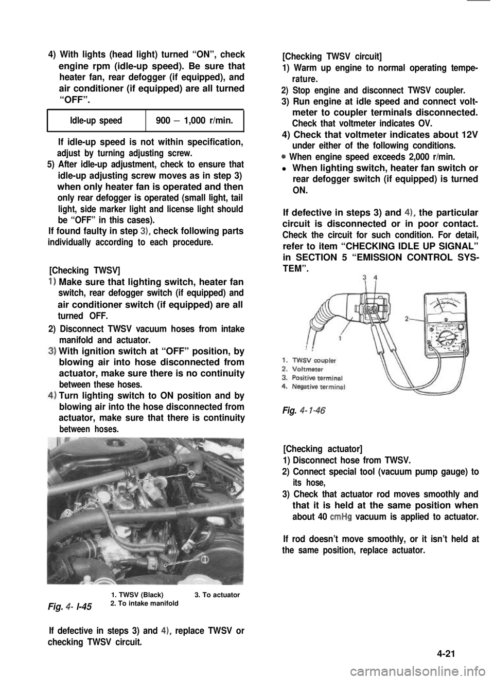
[Checking TWSV]
1) Make sure that lighting switch, heater fan
switch, rear defogger switch (if equipped) and
air conditioner switch (if equipped) are all
turned OFF.
2) Disconnect TWSV vacuum hoses from intake
manifold and actuator.
With ignition switch at “OFF” position, by
blowing air into hose disconnected from
actuator, make sure there is no continuity
between these hoses.
Turn lighting switch to ON position and by
blowing air into the hose disconnected from
actuator, make sure that there is continuity
between hoses.
Fig. 4- l-45
1. TWSV (Black)2. To intake manifold3. To actuator
[Checking TWSV circuit]
1) Warm up engine to normal operating tempe-
rature.
2) Stop engine and disconnect TWSV coupler.
3) Run engine at idle speed and connect volt-
meter to coupler terminals disconnected.
Check that voltmeter indicates OV.
4) Check that voltmeter indicates about 12V
under either of the following conditions.
0 When engine speed exceeds 2,000 r/min.
l When lighting switch, heater fan switch or
rear defogger switch (if equipped) is turned
ON.
If defective in steps 3) and 4), the particular
circuit is disconnected or in poor contact.
Check the circuit for such condition. For detail,
refer to item “CHECKING IDLE UP SIGNAL”
in SECTION 5 “EMISSION CONTROL SYS-
TEM”.
Fig. 4- l-46
[Checking actuator]
1) Disconnect hose from TWSV.
2) Connect special tool (vacuum pump gauge) to
its hose,
3) Check that actuator rod moves smoothly and
that it is held at the same position when
about 40 cmHg vacuum is applied to actuator.
If rod doesn’t move smoothly, or it isn’t held at
the same position, replace actuator.
If defective in steps 3) and 4), replace TWSV or
checking TWSV circuit.
4-21
Page 141 of 962
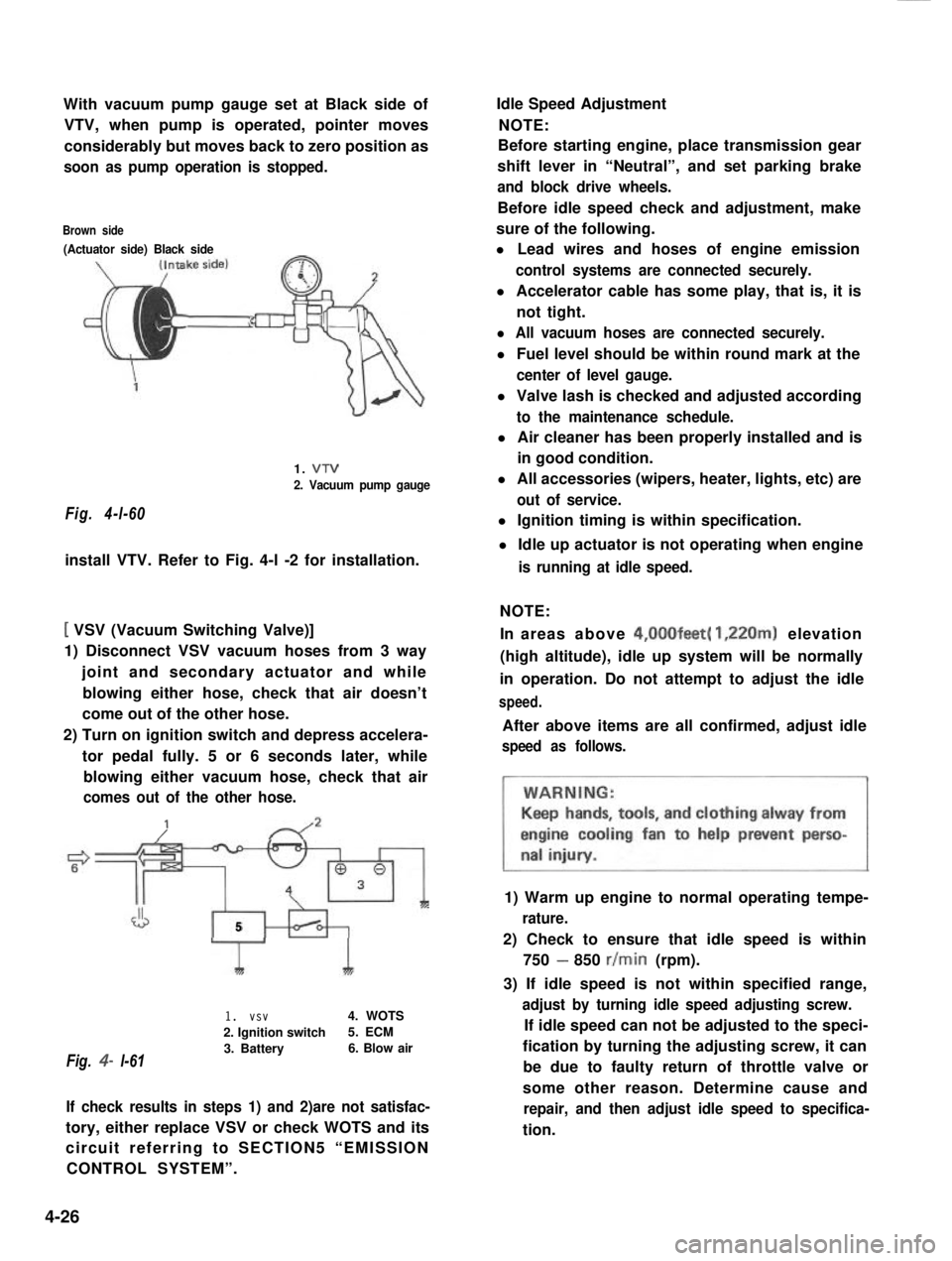
With vacuum pump gauge set at Black side of
VTV, when pump is operated, pointer moves
considerably but moves back to zero position as
soon as pump operation is stopped.
Brown side
(Actuator side) Black side
Fig. 4-l-60
1. VTV
2. Vacuum pump gauge
install VTV. Refer to Fig. 4-l -2 for installation.
[ VSV (Vacuum Switching Valve)]
1) Disconnect VSV vacuum hoses from 3 way
joint and secondary actuator and while
blowing either hose, check that air doesn’t
come out of the other hose.
2) Turn on ignition switch and depress accelera-
tor pedal fully. 5 or 6 seconds later, while
blowing either vacuum hose, check that air
comes out of the other hose.
J5
Fig. 4- l-61
1I
1. vsv4. WOTS
2. Ignition switch5. ECM
3. Battery6. Blow air
If check results in steps 1) and 2)are not satisfac-
tory, either replace VSV or check WOTS and its
circuit referring to SECTION5 “EMISSION
CONTROL SYSTEM”.
Idle Speed Adjustment
NOTE:
Before starting engine, place transmission gear
shift lever in “Neutral”, and set parking brake
and block drive wheels.
Before idle speed check and adjustment, make
sure of the following.
l Lead wires and hoses of engine emission
control systems are connected securely.
l Accelerator cable has some play, that is, it is
not tight.
l All vacuum hoses are connected securely.
l Fuel level should be within round mark at the
center of level gauge.
l Valve lash is checked and adjusted according
to the maintenance schedule.
l Air cleaner has been properly installed and is
in good condition.
l All accessories (wipers, heater, lights, etc) are
out of service.
l Ignition timing is within specification.
l Idle up actuator is not operating when engine
is running at idle speed.
NOTE:
In areas above 4,00Ofeet( 1,220m) elevation
(high altitude), idle up system will be normally
in operation. Do not attempt to adjust the idle
speed.
After above items are all confirmed, adjust idle
speed as follows.
1) Warm up engine to normal operating tempe-
rature.
2) Check to ensure that idle speed is within
750 - 850 r/min (rpm).
3) If idle speed is not within specified range,
adjust by turning idle speed adjusting screw.
If idle speed can not be adjusted to the speci-
fication by turning the adjusting screw, it can
be due to faulty return of throttle valve or
some other reason. Determine cause and
repair, and then adjust idle speed to specifica-
tion.
4-26