1987 SUZUKI GRAND VITARA steering wheel
[x] Cancel search: steering wheelPage 20 of 962
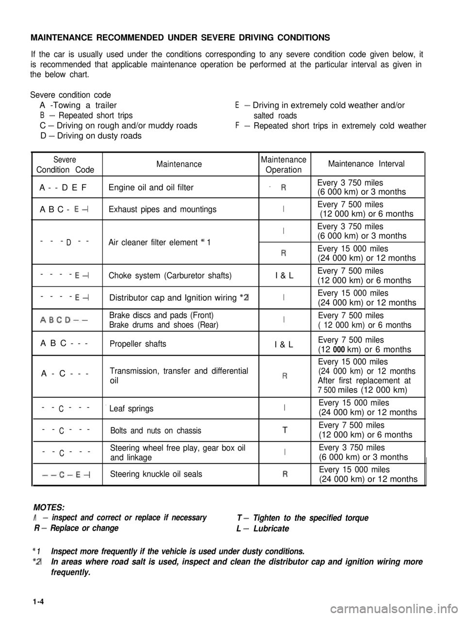
MAINTENANCE RECOMMENDED UNDER SEVERE DRIVING CONDITIONS
If the car is usually used under the conditions corresponding to any severe condition code given below, it
is recommended that applicable maintenance operation be performed at the particular interval as given in
the below chart.
Severe condition code
A -Towing a trailer
B- Repeated short trips
C - Driving on rough and/or muddy roads
D - Driving on dusty roads
E- Driving in extremely cold weather and/or
salted roads
F- Repeated short trips in extremely cold weather
Severe
Condition CodeMaintenanceMaintenance
OperationMaintenance Interval
A--DEFEngine oil and oil filter_ REvery 3 750 miles
(6 000 km) or 3 months
ABC- E-Exhaust pipes and mountingsIEvery 7 500 miles
(12 000 km) or 6 months
IEvery 3 750 miles
D(6 000 km) or 3 months--- --Air cleaner filter element * 1
REvery 15 000 miles
(24 000 km) or 12 months
----E-Choke system (Carburetor shafts)I&LEvery 7 500 miles
(12 000 km) or 6 months
----E-Distributor cap and Ignition wiring “2IEvery 15 000 miles
(24 000 km) or 12 months
ABCD--Brake discs and pads (Front)IEvery 7 500 miles
Brake drums and shoes (Rear)( 12 000 km) or 6 months
ABC---Propeller shaftsI&LEvery 7 500 miles
(12 000 km) or 6 months
Every 15 000 miles
A-C---Transmission, transfer and differential(24 000 km) or 12 months
oilRAfter first replacement at
7 500 miles (12 000 km)
CEvery 15 000 miles-- ---’ Leaf springsI(24 000 km) or 12 months
C-- ---Bolts and nuts on chassisTEvery 7 500 miles
(12 000 km) or 6 months
CSteering wheel free play, gear box oil-- ---and linkageIEvery 3 750 miles
(6 000 km) or 3 months
--C-E-Steering knuckle oil sealsREvery 15 000 miles
(24 000 km) or 12 months
MOTES:
I- inspect and correct or replace if necessary
R - Replace or change
T - Tighten to the specified torque
L - Lubricate
* 1Inspect more frequently if the vehicle is used under dusty conditions.
*2In areas where road salt is used, inspect and clean the distributor cap and ignition wiring more
frequently.
1-4
Page 26 of 962
8. PCV VALVE REPLACEMENT
1) Disconnect crankcase ventilation hose from
PCV valve.
2) Remove PCV valve from intake manifold.
3) Wind sealing tape on thread of the new valve
and install it securely.
Tightenlng torque
for PCV valve
15-25 N.m
1.5-2.5 kg-m,
11 .O-18.0 lb-ft
4) Install hose and clamp it securely.
9. OXYGEN SENSOR REPLACEMENT
[Canadian specification vehicle]
When the odometer indicates 50,000 and 100,000
miles, replace oxygen sensor as follows.
CAUTION:
To avoid the danger of being burned, do
not touch the exhaust system when the
system is hot. This work should be perform-
ed when the system is cool.
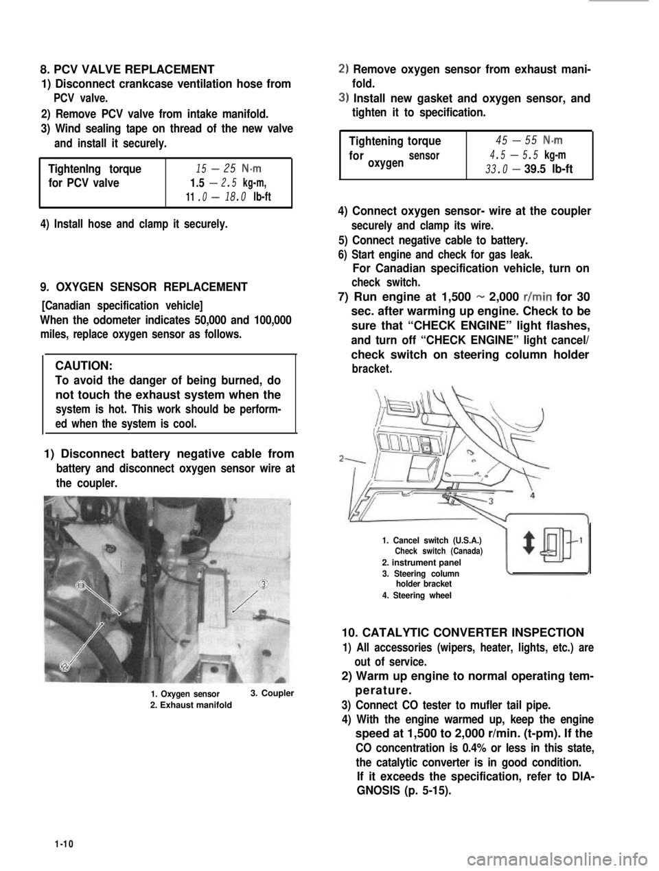
1) Disconnect battery negative cable from
battery and disconnect oxygen sensor wire at
the coupler.
1. Oxygen sensor
2. Exhaust manifold
3. Coupler
2) Remove oxygen sensor from exhaust mani-
fold.
3) Install new gasket and oxygen sensor, and
tighten it to specification.
-Tightening45torque55 N-m
4.5-foroxygensensor5.5 kg-m
33.0-39.5 lb-ft
4) Connect oxygen sensor- wire at the coupler
securely and clamp its wire.
5) Connect negative cable to battery.
6) Start engine and check for gas leak.
For Canadian specification vehicle, turn on
check switch.
7) Run engine at 1,500 - 2,000 r/min for 30
sec. after warming up engine. Check to be
sure that “CHECK ENGINE” light flashes,
and turn off “CHECK ENGINE” light cancel/
check switch on steering column holder
bracket.
1. Cancel switch (U.S.A.)Check switch (Canada)
2. instrument panel
3. Steering columnholder bracket
4. Steering wheel
10. CATALYTIC CONVERTER INSPECTION
1) All accessories (wipers, heater, lights, etc.) are
out of service.
2) Warm up engine to normal operating tem-
perature.
3) Connect CO tester to mufler tail pipe.
4) With the engine warmed up, keep the engine
speed at 1,500 to 2,000 r/min. (t-pm). If the
CO concentration is 0.4% or less in this state,
the catalytic converter is in good condition.
If it exceeds the specification, refer to DIA-
GNOSIS (p. 5-15).
1-10
Page 34 of 962
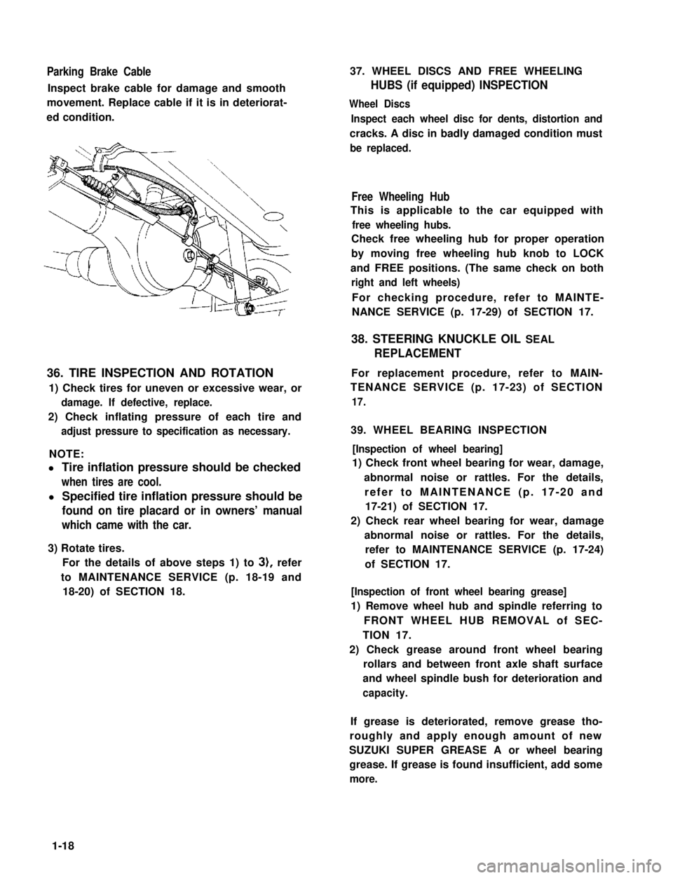
Parking Brake Cable
Inspect brake cable for damage and smooth
movement. Replace cable if it is in deteriorat-
ed condition.
36. TIRE INSPECTION AND ROTATION
1) Check tires for uneven or excessive wear, or
damage. If defective, replace.
2) Check inflating pressure of each tire and
adjust pressure to specification as necessary.
NOTE:
l Tire inflation pressure should be checked
when tires are cool.
l Specified tire inflation pressure should be
found on tire placard or in owners’ manual
which came with the car.
3) Rotate tires.
For the details of above steps 1) to 3), refer
to MAINTENANCE SERVICE (p. 18-19 and
18-20) of SECTION 18.
37. WHEEL DISCS AND FREE WHEELING
HUBS (if equipped) INSPECTION
Wheel Discs
Inspect each wheel disc for dents, distortion and
cracks. A disc in badly damaged condition must
be replaced.
Free Wheeling Hub
This is applicable to the car equipped with
free wheeling hubs.
Check free wheeling hub for proper operation
by moving free wheeling hub knob to LOCK
and FREE positions. (The same check on both
right and left wheels)
For checking procedure, refer to MAINTE-
NANCE SERVICE (p. 17-29) of SECTION 17.
38. STEERING KNUCKLE OIL SEAL
REPLACEMENT
For replacement procedure, refer to MAIN-
TENANCE SERVICE (p. 17-23) of SECTION
17.
39. WHEEL BEARING INSPECTION
[Inspection of wheel bearing]
1) Check front wheel bearing for wear, damage,
abnormal noise or rattles. For the details,
refer to MAINTENANCE (p. 17-20 and
17-21) of SECTION 17.
2) Check rear wheel bearing for wear, damage
abnormal noise or rattles. For the details,
refer to MAINTENANCE SERVICE (p. 17-24)
of SECTION 17.
[Inspection of front wheel bearing grease]
1) Remove wheel hub and spindle referring to
FRONT WHEEL HUB REMOVAL of SEC-
TION 17.
2) Check grease around front wheel bearing
rollars and between front axle shaft surface
and wheel spindle bush for deterioration and
capacity.
If grease is deteriorated, remove grease tho-
roughly and apply enough amount of new
SUZUKI SUPER GREASE A or wheel bearing
grease. If grease is found insufficient, add some
more.
1-18
Page 37 of 962
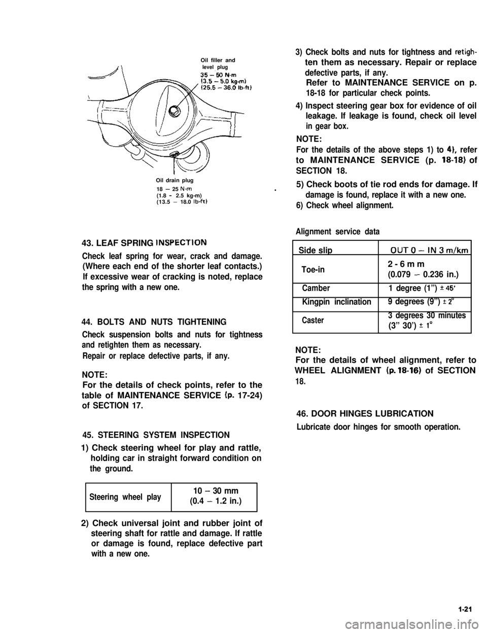
Oil filler andlevel plug
Oil drain plug
18 - 25 N.m(1.8 - 2.5 kg-m)(13.5 - 18.0 lb-ft)
43. LEAF SPRING lNSPECTlON
Check leaf spring for wear, crack and damage.
(Where each end of the shorter leaf contacts.)
If excessive wear of cracking is noted, replace
the spring with a new one.
44. BOLTS AND NUTS TIGHTENING
Check suspension bolts and nuts for tightness
and retighten them as necessary.
Repair or replace defective parts, if any.
NOTE:
For the details of check points, refer to the
table of MAINTENANCE SERVICE (p. 17-24)
of SECTION 17.
45. STEERING SYSTEM INSPECTION
1) Check steering wheel for play and rattle,
holding car in straight forward condition on
the ground.
Steering wheel play10 - 30 mm
(0.4 - 1.2 in.)
3) Check bolts and nuts for tightness and retigh-
ten them as necessary. Repair or replace
defective parts, if any.
Refer to MAINTENANCE SERVICE on p.
18-18 for particular check points.
4) Inspect steering gear box for evidence of oil
leakage. If leakage is found, check oil level
in gear box.
NOTE:
For the details of the above steps 1) to 41, refer
to MAINTENANCE SERVICE (p. 18-18) of
SECTION 18.
.5) Check boots of tie rod ends for damage. If
damage is found, replace it with a new one.
6) Check wheel alignment.
Alignment service data
Side slipOUTO-IN3m/km
Toe-in2-6mm
(0.079 - 0.236 in.)
Camber1 degree (1”) *45’
Kingpin inclination 9 degrees (9”) f 2’
Caster3 degrees 30 minutes
(3” 30’) f I0
NOTE:
For the details of wheel alignment, refer to
WHEEL ALIGNMENT (p. 18-16) of SECTION
18.
46. DOOR HINGES LUBRICATION
Lubricate door hinges for smooth operation.
2) Check universal joint and rubber joint of
steering shaft for rattle and damage. If rattle
or damage is found, replace defective part
with a new one.
1-21
Page 38 of 962

FINAL INSPECTION
Carry out road test in safe place.
WARNING:
When carrying out the following road
tests, select a safe place where no man or
no running car is seen so as to prevent any
accident.
1) Engine start
Check engine start for readiness.
2) Clutch
Check the following:
l that clutch is completely released when
depressing clutch pedal,
l that no slipping clutch occurs when releas-
ing pedal and accelerating,
l and that clutch itself is free from any
abnormal condition.
3) Gearshift Lever (Transmission and Transfer)
Check gearshift lever for smooth shifting
to all positions and for good performance of
transmission and transfer in any position.
4) Brake
[Foot brake]
Check the following when depressing brake
pedal while driving;
l that brake works properly,
l that it is free from noise,
l and that braking force applies equally on
all wheels.
[Parking brake]
Check to ensure that parking brake is fully
effective when the car is stopped on the slop
and brake lever is pulled all the way.
5) Steering
Check to ensure that steering wheel is free
from instability, or abnormally heavy feeling
while driving.
1-22
Page 52 of 962

2-9. SUSPENSION, STEERING SYSTEM AND TIRES
Condition
Hard steering
Possible causeCorrection
1. Wheel tires not adequately inflatedAdjust the pressure
2. Bind in tie rod end ball studReplace
3. Linkage connections tending to seizeRepair or replace
4. Steering gearbox out of adjustmentAdjust as prescribed
5. Unevenly worn steering shaft bushReplace
6. Disturbed front wheel alignmentAdjust as prescribed
Wobbly steering wheel1. Wheel tires inflated unequallyAdjust tire pressure
(Shimmy, shake or2. Wobbly wheelsRepair or replace
vibration)3. Large difference in tire diameter betweenReplace._
right and left wheels
4. Loose hub nutsRetighten
5. Damaged or worn wheel bearingsReplace
6. Worn or loose tie rod endsReplace or retighten
7. Steering gearbox out of adjustmentAdjust as prescribed
8. Steering gearbox mounted looseRetighten
9. Worn steering knuckle oil sealReplace
10. Tire or wheel out of balanceBalance wheel or replace tire
and/or wheel
11. Blister or bump on tireReplace tire
12. Disturbed front wheel alignmentCheck front wheel alignment
Steering wheel
pulling to one
side (car pulls)
1. Unevenly worn wheel tires
2. Brake dragging in one road wheel
3. Wheel tires unequally inflated
4. Worn or distorted link rods
5. Disturbed front wheel alignment
6. Loose, bent or broken front or rear
suspension parts
Replace
Repair
Adjust tire pressure
Replace
Adjust as prescribed
Tighten or replace suspension
parts
Shocks coming to1. Tire inflating pressure too highReduce to the specification
steering wheel2. Poor shock absorber performanceReplace
(or wheel tramp)3. Differences in tire diameter among fourAdjust
road wheels
4. Worn steering linkage connectionsReplace
5. Worn or broken front wheel bearingsReplace
6. Loose front wheelRetighten
7. Steering wheel loose in placeRetighten the nut
8. Blister or bump on tireReplace tire
Rapid wear or uneven1. Wheel tires imporperly inflatedAdjust tire pressure
wear of wheel tires2. Differences in diameter among four tiresAdjust or replace
(Abnormal or excessive3. Worn or loose road wheel bearingsReplace
tire wear)4. Wobbly wheel tiresRepair or replace
2-14
Page 53 of 962

ConditionPossible causeCorrection
Rapid wear or uneven5. Wheel tires improperly “rotated“ toAdjust
wear of wheel tiresresult in unbalance
(Abnormal or excessive6. Disturbed front wheel alignmentAdjust as prescribed
tire wear)7. Hard drivingReplace tire
Steering noise1. Loose bolts and nuts
2. Loose leaf spring seats
3. Broken or otherwise damaged wheel
bearings
4. Worn or sticky tie rod ends
5. Linkage joints needling grease
Retighten
Retighten
Replace
Replace
Lubricate or replace
Too much play in
steering
1. Worn wheel bearings .Replace wheel bearing
2. Steering gear box attachments looseTighten or repair
3. Steering gear box adjustmentsCheck and adjust
4. Worn steering shaft jointsReplace joint
5. Worn tie rod ends or drug rod ball jointsReplace tie rod end or tie rod
Poor returnability1. Bind in tie rod end ball studs
2. Bind in steering column
3. Lack of lubricant steering gear box
4. Disturbed front end alignment
5. Steering gear box adjustment
6. Tires not adequatley inflated
Replace tie rod end
Repair or replace
Check, lubricate or replace
Check and adjust front end
alignment
Check and adjust gear box
torque
Adjust pressure
Abnormal noise,
front end
1. Worn, sticky or loose tie rod ends, drug
rod ball joints or axle shaft joints
2. Damaged shock absorbers or mountings
3. Loose stabilizer bar
4. Loose wheel nuts
5. Loose suspension bolts or nuts
6. Broken or otherwise damaged wheel
bearings
7. Broken suspension springs
Replace tie rod ends, drug
rod or axle shaft joints
Replace or repair
Tighten bolts or replace bushe!
Tighten
Tighten suspension bolts or
nuts
Replace
Replace
Wander or poor
steering stability
1. Mismatched or uneven tires
2. Loose tie rod ends or drug rod
3. Faulty shock absorber or mounting
Replace tire or inflate tires to
proper pressure
Replace tie rod end or drug ro(
Replace absorber or repair
mounting
2-15
Page 54 of 962
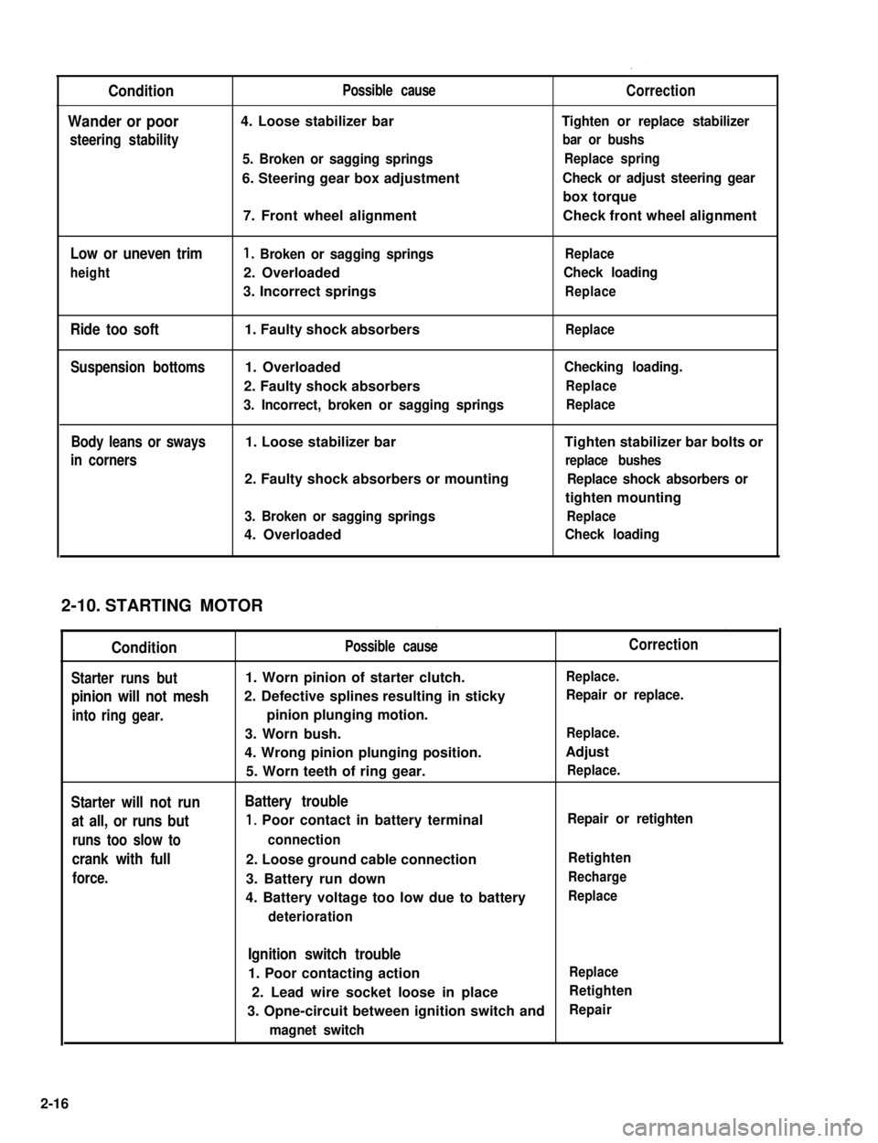
Condition
Wander or poor
steering stability
Low or uneven trim
height
Ride too soft
Suspension bottoms
Body leans or sways
in corners
Possible cause
4. Loose stabilizer bar
5. Broken or sagging springs
6. Steering gear box adjustment
7. Front wheel alignment
1. Broken or sagging springs
2. Overloaded
3. Incorrect springs
1. Faulty shock absorbers
1. Overloaded
2. Faulty shock absorbers
3. Incorrect, broken or sagging springs
1. Loose stabilizer bar
2. Faulty shock absorbers or mounting
3. Broken or sagging springs
4. Overloaded
Correction
Tighten or replace stabilizer
bar or bushs
Replace spring
Check or adjust steering gear
box torque
Check front wheel alignment
Replace
Check loading
Replace
Replace
Checking loading.
Replace
Replace
Tighten stabilizer bar bolts or
replace bushes
Replace shock absorbers or
tighten mounting
Replace
Check loading
STARTING MOTOR
Condition
Starter runs but
pinion will not mesh
into ring gear.
Starter will not run
at all, or runs but
runs too slow to
crank with full
force.
Possible cause
1. Worn pinion of starter clutch.
2. Defective splines resulting in sticky
pinion plunging motion.
3. Worn bush.
4. Wrong pinion plunging position.
5. Worn teeth of ring gear.
Battery trouble
1, Poor contact in battery terminal
connection
2. Loose ground cable connection
3. Battery run down
4. Battery voltage too low due to battery
deterioration
Correction
Replace.
Repair or replace.
Replace.
Adjust
Replace.
Repair or retighten
Retighten
Recharge
Replace
Ignition switch trouble
1. Poor contacting actionReplace
2. Lead wire socket loose in placeRetighten
3. Opne-circuit between ignition switch andRepair
magnet switch
2-10.
2-16