1987 SUZUKI GRAND VITARA differential
[x] Cancel search: differentialPage 2 of 962
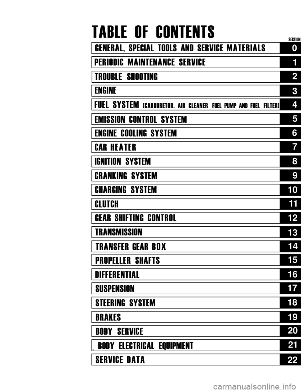
TABLE OF CONTENTS
GENERAL, SPECIAL TOOLS AND SERVICE MATERIALS
PERIODIC MAINTENANCE SERVICE
TROUBLE SHOOTING
ENGINE
FUEL SYSTEM (CARBURETOR, AIR CLEANER FUEL PUMP AND FUEL FILTER)
EMISSION CONTROL SYSTEM
ENGINE COOLING SYSTEM
CAR HEATER
IGNITION SYSTEM
CRANKING SYSTEM
CHARGING SYSTEM
CLUTCH
GEAR SHIFTING CONTROL
TRANSMISSION
TRANSFER GEAR BOX
PROPELLER SHAFTS
DIFFERENTIAL
SUSPENSION
STEERING SYSTEM
BRAKES
BODY SERVICE
,i BODY ELECTRICAL EQUIPMENT
SERVICE DATA
0
1
2
5
6
7
8
9
10
1111
12
13
14
15
16
17
18
19
20
21
22
4
3
SECTION
Page 4 of 962
O-2. STANDARD SHOP PRACTICES
1. Protect painted surfaces of the body, and
avoid staining or tearing seats. When working
on fenders and seats, be sure to cover them
up with sheets.
2. Disconnect negative terminal connection of
the battery when working on any electrical
part or component. This is necessary for
avoiding electrical shocks and short-circuit-
ing, and is very simple to accomplish: merely
loosen wing nut on negative terminal and
separate cable from terminal post.
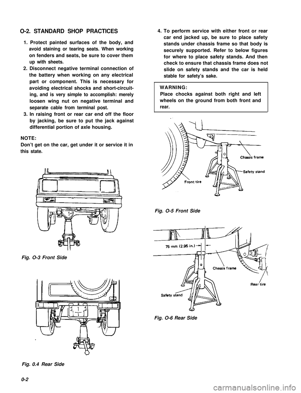
3. In raising front or rear car end off the floor
by jacking, be sure to put the jack against
differential portion of axle housing.
NOTE:
Don’t get on the car, get under it or service it in
this state.
Fig. O-3 Front Side
4. To perform service with either front or rear
car end jacked up, be sure to place safety
stands under chassis frame so that body is
securely supported. Refer to below figures
for where to place safety stands. And then
check to ensure that chassis frame does not
slide on safety stands and the car is held
stable for safety’s sake.
WARNING:
Place chocks against both right and left
wheels on the ground from both front and
rear.
Fig. O-5 Front Side
&
Fig. O-6 Rear Side
Fig. 0.4 Rear Side
0-2
Page 20 of 962
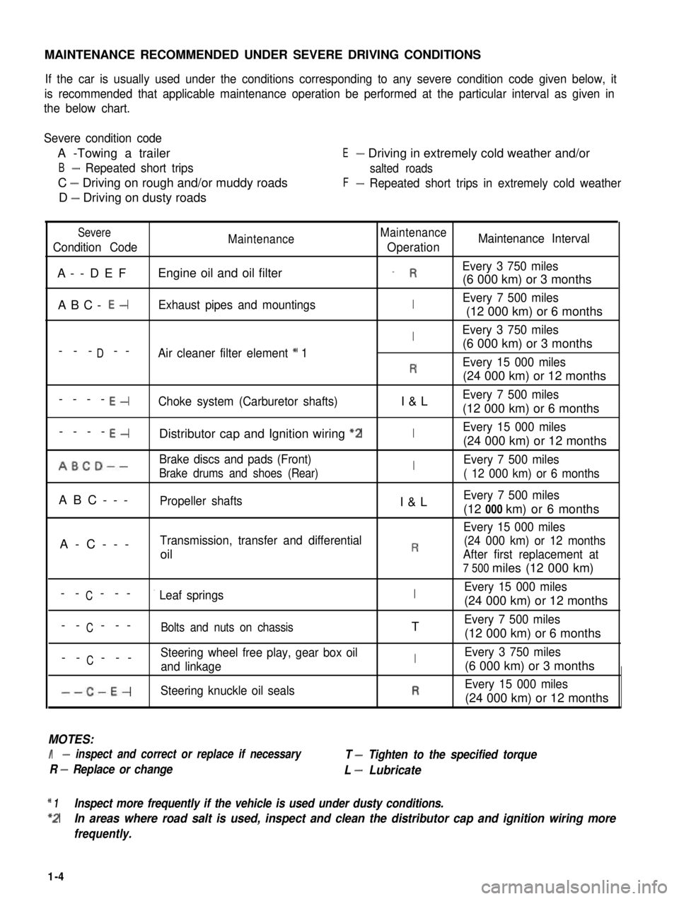
MAINTENANCE RECOMMENDED UNDER SEVERE DRIVING CONDITIONS
If the car is usually used under the conditions corresponding to any severe condition code given below, it
is recommended that applicable maintenance operation be performed at the particular interval as given in
the below chart.
Severe condition code
A -Towing a trailer
B- Repeated short trips
C - Driving on rough and/or muddy roads
D - Driving on dusty roads
E- Driving in extremely cold weather and/or
salted roads
F- Repeated short trips in extremely cold weather
Severe
Condition CodeMaintenanceMaintenance
OperationMaintenance Interval
A--DEFEngine oil and oil filter_ REvery 3 750 miles
(6 000 km) or 3 months
ABC- E-Exhaust pipes and mountingsIEvery 7 500 miles
(12 000 km) or 6 months
IEvery 3 750 miles
D(6 000 km) or 3 months--- --Air cleaner filter element * 1
REvery 15 000 miles
(24 000 km) or 12 months
----E-Choke system (Carburetor shafts)I&LEvery 7 500 miles
(12 000 km) or 6 months
----E-Distributor cap and Ignition wiring “2IEvery 15 000 miles
(24 000 km) or 12 months
ABCD--Brake discs and pads (Front)IEvery 7 500 miles
Brake drums and shoes (Rear)( 12 000 km) or 6 months
ABC---Propeller shaftsI&LEvery 7 500 miles
(12 000 km) or 6 months
Every 15 000 miles
A-C---Transmission, transfer and differential(24 000 km) or 12 months
oilRAfter first replacement at
7 500 miles (12 000 km)
CEvery 15 000 miles-- ---’ Leaf springsI(24 000 km) or 12 months
C-- ---Bolts and nuts on chassisTEvery 7 500 miles
(12 000 km) or 6 months
CSteering wheel free play, gear box oil-- ---and linkageIEvery 3 750 miles
(6 000 km) or 3 months
--C-E-Steering knuckle oil sealsREvery 15 000 miles
(24 000 km) or 12 months
MOTES:
I- inspect and correct or replace if necessary
R - Replace or change
T - Tighten to the specified torque
L - Lubricate
* 1Inspect more frequently if the vehicle is used under dusty conditions.
*2In areas where road salt is used, inspect and clean the distributor cap and ignition wiring more
frequently.
1-4
Page 36 of 962
3) Check propeller shaft (No. 1, No. 2, No. 3)
flange yoke bolts for tightness, and retighten
them as necessary:
N.mkg-mlb-ftTighteningtorque23-302.3-3.017.0-21.5
42. TRANSMISSION, TRANSFER,
DIFFERENTIAL OIL INSPECTION
AND CHANGE
[I nspectionl
1) Inspect transmission case, transfer case and
differential housing for evidence of oil leakage.
Repair leaky point if any.
2) Make sure that the car is placed level for oil
level check.
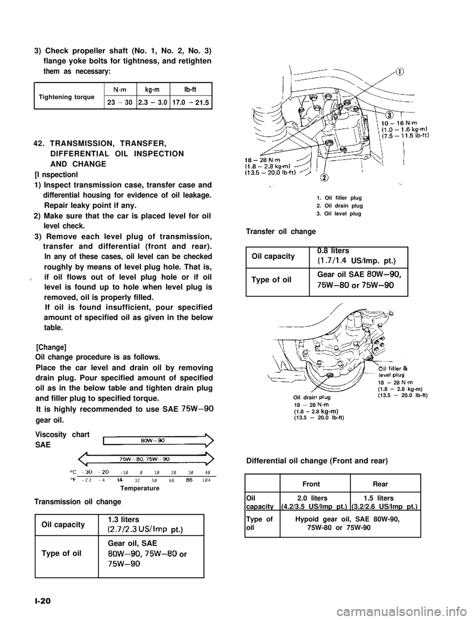
3) Remove each level plug of transmission,
transfer and differential (front and rear).
In any of these cases, oil level can be checked
roughly by means of level plug hole. That is,
,if oil flows out of level plug hole or if oil
level is found up to hole when level plug is
removed, oil is properly filled.
If oil is found insufficient, pour specified
amount of specified oil as given in the below
table.
[Change]
Oil change procedure is as follows.
Place the car level and drain oil by removing
drain plug. Pour specified amount of specified
oil as in the below table and tighten drain plug
and filler plug to specified torque.
It is highly recommended to use SAE 75W-90
gear oil.
Viscosity chart
SAE
75w-ao,75w-90
"C -30 --20 -10 0 10 20 30 40"F -22 -4lb 32 50 68 86104
Temperature
Transmission oil change
Oil capacity
Type of oil
1.3 liters
(2.7/2.3 US/Imp pt.)
Gear oil, SAE
8OW-90,75W-80 or
75w-90
l-20
18-28N.m
I ”’
1. Oil filler plug
2. Oil drain plug
3. Oil level plug
Transfer oil change
Oil capacity0.8 liters
(1.7/l .4 US/Imp. pt.)
Type of oilGear oil SAE 8OW-90,
75W-80 or 75W-90
18 - 28 N.m(1.8 - 2.8 kg-m)(13.5 - 20.0 lb-ft)-R-Oil drair18 - 28 N&(1.8 - 2.8 kg-m)(13.5 - 20.0 lb-ft)
Differential oil change (Front and rear)
1.5 liters
(3.2/2.6 US/Imp pt.)
2.0 liters
(4.2/3.5 US/Imp pt.)
FrontRear
Oil
capacity
Type of
oil
Hypoid gear oil, SAE 80W-90,
75W-80 or 75W-90
Page 39 of 962

2-1.
2-2.
2-3.
2-4.
2-5.
2-6.
2-7.
2-6.
2-9.
SECTION 2
TROUBLE SHOOTING
CONTENTS
ENGINE...................................................2-2
CARBURETOR...........................................
EXHAUST AND MUFFLER.................................
CLUTCH.................................................2-9
TRANSMISSION..........................................
DIFFERENTIALS.........................................2-11
PROPELLER SHAFTS.....................................2-12
BRAKES.............................................. 2-12
SUSPENSION, STEERING SYSTEM AND TIRES................
STARTING MOTOR.....................................
2-11. ALTERNATOR...........................................
FUEL METER............................................ 2-19
2-14. SPEEDOMETER..........................................2-19
2-15. WATER TEMPERATURE METER.............................2-19
2-9
2-9
2-10
2-14
2-16
2-17
2-18WIPER MOTOR.......................................
2-10.
2-12.
2-13.
2-1
2
Page 49 of 962

Condition
Excessive gear noise
Hard shifting
2-6. DIFFERENTIALS
Possible cause
1. Not enough oil in transmission
2. Defective synchronizer
3. Gears rattling in thrust direction
4. Broken or worn bearings
5. Damaged or worn gears
1. Clutch pedal play too large, resulting in a
“dragging clutch”
2. Worn clutch disc facings
3. Clutch disc facings dirty with oil.
4. Distorted or unevenly worn shift fork shaft
5. Broken locating balls
6. Worn synchornizer sleeve or ring
7. Worn synchronizer hub
Condition
Gear noise
Bearing noise
Possible cause
1. Maladjusted backlash between drive pinion
and ring gear
2. Damaged gear teeth or improper mesh of
drive pinion and ring gear
3. Improper tooth contact in the mesh between
drive pinion and ring gear
4. Insufficient or wrong kind of gear oil
5. Ring gear wobbling when turning, or ring
gear securing bolts loose
6. Broken or otherwise damaged teeth of side
gears or differential pinion gears
1. (Constant noise) Insufficient or wrong kind
of gear oil
2. (Constant noise) Damaged or worn bearings
or borne parts
3. (Noise during coasting) Damaged bearings
of rear drive pinion
4. (Noise during turning) Broken bearings
on axle shafts
Correction
Replenish
Replace
Replace
Replace
Replace
Adjust as prescribed
Replace.
Replace.
Replace
Replace
Replace
Replace
Correction
Adjust as prescribed
Replace or adjust
Adjust as prescribed
Replenish or replace
Replace, or retighten
Replace
Replenish or change
Replace.
Replace
Replace
2-11
Page 265 of 962
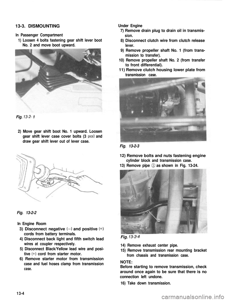
13-3. DISMOUNTINGIn Passenger Compartment
1) Loosen 4 bolts fastening gear shift lever boot
No. 2 and move boot upward.
Fig.
13-2- 1 Under Engine
7) Remove drain plug to drain oil in transmis-
sion.
8) Disconnect clutch wire from clutch release
lever.
9) Remove propeller shaft No. 1 (from trans-
mission to transfer).
10) Remove propeller shaft No. 2 (from transfer
to front differential).
11) Remove clutch housing lower plate from
transmission case.
2) Move gear shift boot No. 1 upward. Loosen
gear shift lever case cover bolts (3
PCS) and
draw gear shift lever out of lever case.
Fig. 13-2-3
Fig. 13-2-2 In Engine Room
3) Disconnect negative (-) and positive (+)
cords from battery terminals.
4) Disconnect back light and fifth switch lead
wires at coupler respectively.
5) Disconnect Black/Yellow lead wire and posi- tive
(+) cord from starter motor.
6) Remove starter motor from transmission
case and fuel hoses clamp from transmission
case.
12) Remove bolts and nuts fastening engine
cylinder block and transmission case.
13) Remove pipe (iJ as shown in Fig. 13-24.
Fig. 13-2-4
14) Remove exhaust center pipe.
15) Remove transmission rear mounting bracket
from chassis and transmission case.
NOTE:
Before starting to remove transmission, check
around once again to be sure that there is no
connection left undone.
16) Take down transmission.
13-4
Page 312 of 962
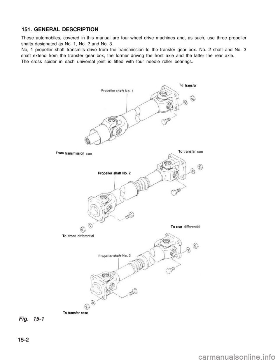
151. GENERAL DESCRIPTION
These automobiles, covered in this manual are four-wheel drive machines and, as such, use three propeller
shafts designated as No. 1, No. 2 and No. 3.
No, 1 propeller shaft transmits drive from the transmission to the transfer gear box. No. 2 shaft and No. 3
shaft extend from the transfer gear box, the former driving the front axle and the latter the rear axle.
The cross spider in each universal joint is fitted with four needle roller bearings.
From
TQ transfer
transmission casaTo transfar casa
Propeller shaft No. 2
To rear differential
To front differential
To transfer case
15-2
Fig. 15-1