Page 328 of 962
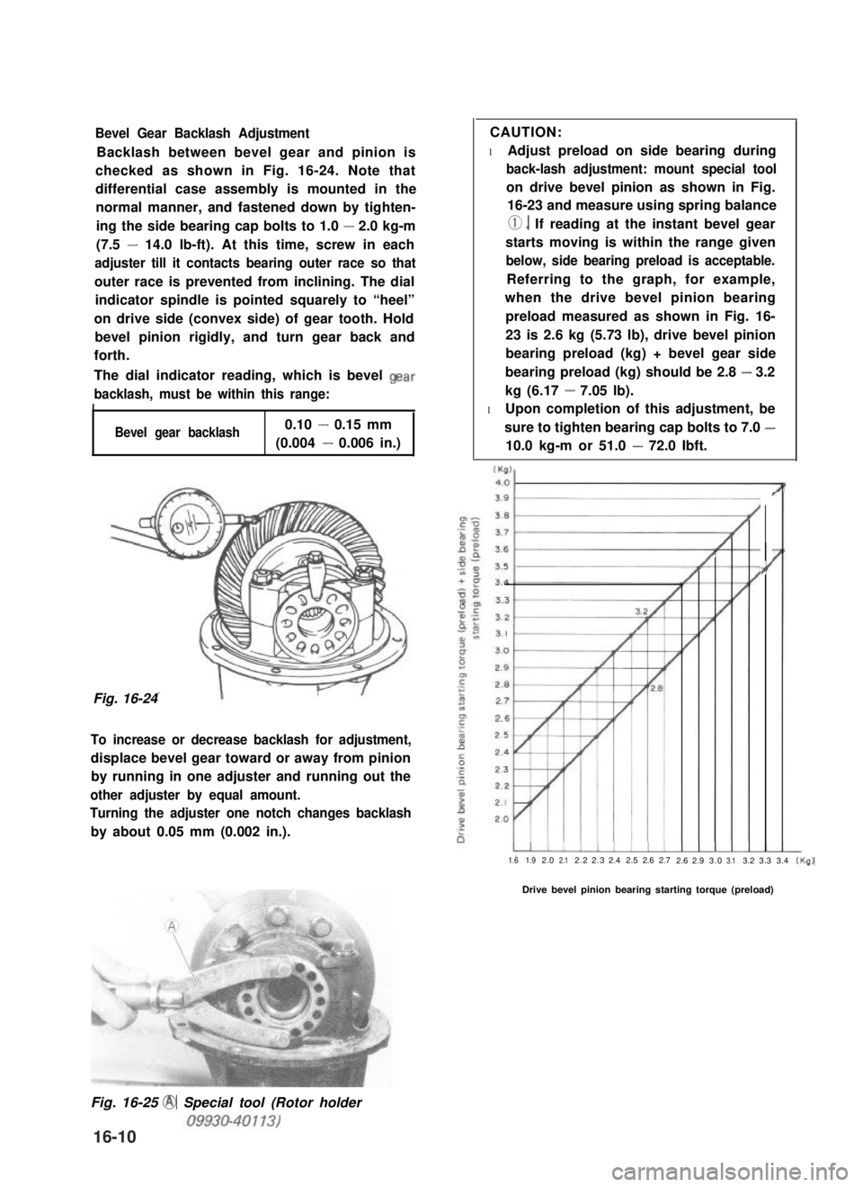
Bevel Gear Backlash Adjustment
Backlash between bevel gear and pinion is
checked as shown in Fig. 16-24. Note that
differential case assembly is mounted in the
normal manner, and fastened down by tighten-
ing the side bearing cap bolts to 1.0 - 2.0 kg-m
(7.5 - 14.0 lb-ft). At this time, screw in each
adjuster till it contacts bearing outer race so that
outer race is prevented from inclining. The dial
indicator spindle is pointed squarely to “heel”
on drive side (convex side) of gear tooth. Hold
bevel pinion rigidly, and turn gear back and
forth.
The dial indicator reading, which is bevel Qear
backlash, must be within this range:
I
Bevel gear backlash0.10 - 0.15 mm
(0.004 - 0.006 in.)
Fig. 16-24
To increase or decrease backlash for adjustment,
displace bevel gear toward or away from pinion
by running in one adjuster and running out the
other adjuster by equal amount.
Turning the adjuster one notch changes backlash
by about 0.05 mm (0.002 in.).
CAUTION:
l Adjust preload on side bearing during
back-lash adjustment: mount special tool
on drive bevel pinion as shown in Fig.
16-23 and measure using spring balance
0. If reading at the instant bevel gear
starts moving is within the range given
below, side bearing preload is acceptable.
Referring to the graph, for example,
when the drive bevel pinion bearing
preload measured as shown in Fig. 16-
23 is 2.6 kg (5.73 lb), drive bevel pinion
bearing preload (kg) + bevel gear side
bearing preload (kg) should be 2.8 - 3.2
kg (6.17 - 7.05 lb).
l Upon completion of this adjustment, be
sure to tighten bearing cap bolts to 7.0 -
10.0 kg-m or 51.0 - 72.0 Ibft.
?’
1.61.92.02.12.22.32.42.52.62.72.62.93.03.13.23.33.4(Kg)
Drive bevel pinion bearing starting torque (preload)
Fig. 16-25 @ Special tool (Rotor holder
16-10
Page 329 of 962
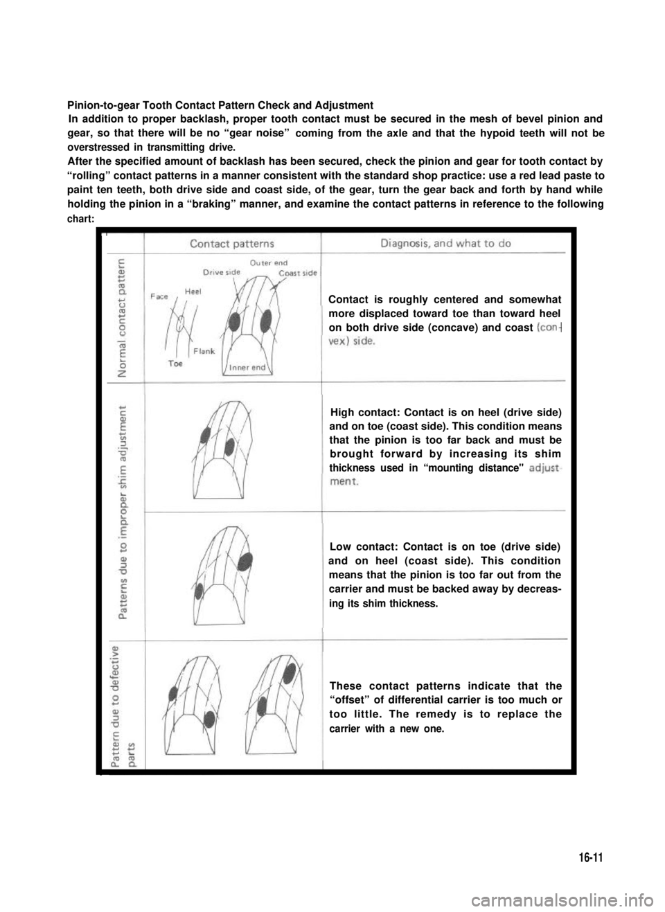
Pinion-to-gear Tooth Contact Pattern Check and Adjustment
In addition to proper backlash, proper tooth contact must be secured in the mesh of bevel pinion and
gear, so that there will be no “gear noise”coming from the axle and that the hypoid teeth will not be
overstressed in transmitting drive.
After the specified amount of backlash has been secured, check the pinion and gear for tooth contact by
“rolling” contact patterns in a manner consistent with the standard shop practice: use a red lead paste to
paint ten teeth, both drive side and coast side, of the gear, turn the gear back and forth by hand while
holding the pinion in a “braking” manner, and examine the contact patterns in reference to the following
chart:
c
Contact is roughly centered and somewhat
more displaced toward toe than toward heel
on both drive side (concave) and coast
High contact: Contact is on heel (drive side)
and on toe (coast side). This condition means
that the pinion is too far back and must be
brought forward by increasing its shim
thickness used in “mounting distance" adjust-
Low contact: Contact is on toe (drive side)
and on heel (coast side). This condition
means that the pinion is too far out from the
carrier and must be backed away by decreas-
ing its shim thickness.
These contact patterns indicate that the
“offset” of differential carrier is too much or
too little. The remedy is to replace the
carrier with a new one.
16-11
Page 330 of 962
rIContact patterns1Diagnosis, and what to do
These contact patterns, located on toe or heel
on both drive and coast sides, mean that 1)
both pinion and gear are defective, 2) carrier
is not true and square, or 3) gear is not
properly seated on differential case. The
remedy is to replace the defective member.
Irregular patterns: If the pattern is not oval,
it means that bevel gear is defective. High or
low spots on tooth surfaces or on the seat of
bevel gear are the cause of irregular patterns
appearing on some teeth. The remedy is to
replace the pinion and-gear set and, if the seat
is defective, so is differential case.
CAUTION:
When applying red lead paste to teeth, be sure to paint tooth surfaces uniformly. The paste must not
be too dry or too fluid.
16-12
Page 331 of 962
16-5. REASSEMBLY
Reverse disassembly procedure for reassembly,
noting the following.
NOTE:
Bevel pinion and bevel gear are supplied as a
set. Even when only bevel pinion or bevel gear
replacement is necessary, be sure to replace
both as a set.
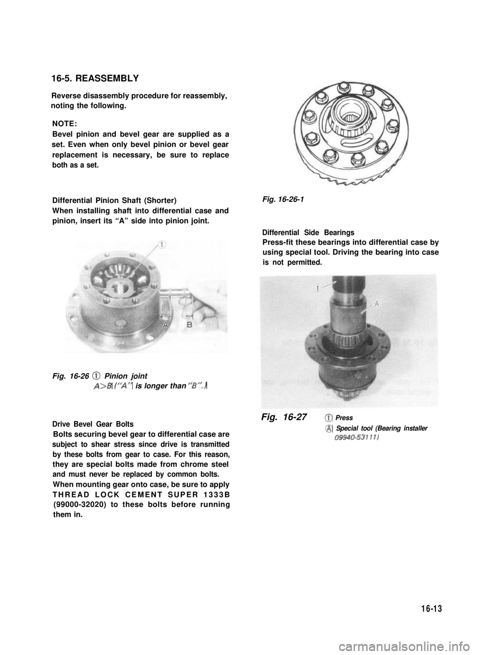
Differential Pinion Shaft (Shorter)
When installing shaft into differential case and
pinion, insert its “A” side into pinion joint.
Fig. 16-26 @ Pinion joint
A>B (“A” is longer than ‘/Br’.)
Drive Bevel Gear Bolts
Bolts securing bevel gear to differential case are
subject to shear stress since drive is transmitted
by these bolts from gear to case. For this reason,
they are special bolts made from chrome steel
and must never be replaced by common bolts.
When mounting gear onto case, be sure to apply
THREAD LOCK CEMENT SUPER 1333B
(99000-32020) to these bolts before running
them in.
Fig. 16-26-1
Differential Side Bearings
Press-fit these bearings into differential case by
using special tool. Driving the bearing into case
is not permitted.
Fig. 16-27@ Press
@ Special tool (Bearing installer
09940-53111)
16-13
Page 332 of 962
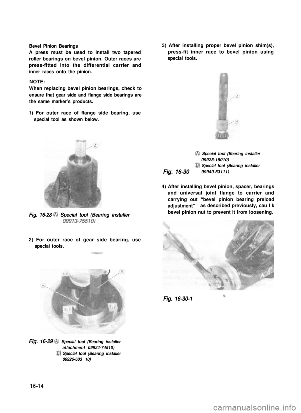
Bevel Pinion Bearings
A press must be used to install two tapered
roller bearings on bevel pinion. Outer races are
press-fitted into the differential carrier and
inner races onto the pinion.
NOTE:
When replacing bevel pinion bearings, check to
ensure that gear side and flange side bearings are
the same marker’s products.
1) For outer race of flange side bearing, use
special tool as shown below.
Fig. 16-28 @ Special tool (Bearing installer
09913-75510)
2) For outer race of gear side bearing, use
special tools.
3) After installing proper bevel pinion shim(s),
press-fit inner race to bevel pinion using
special tools.
@ Special tool (Bearing installer
09925-18010)
Fig. 16-30
@ Special tool (Bearing installer
09940-53111)
4) After installing bevel pinion, spacer, bearings
and universal joint flange to carrier and
carrying out “bevel pinion bearing preload
adjustment”as described previously, cau I k
bevel pinion nut to prevent it from loosening.
Fig. 16-30-1
Fig. 16-29 @ Special tool (Bearing installer
attachment 09924-74510)
@ Special tool (Bearing installer
09926-683 10)
16-14
Page 333 of 962
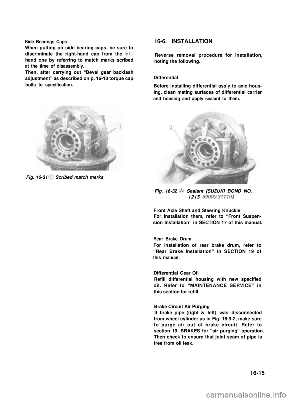
Side Bearings Caps
When putting on side bearing caps, be sure to
discriminate the right-hand cap from the left-
hand one by referring to match marks scribed
at the time of disassembly.
Then, after carrying out “Bevel gear backlash
adjustment” as described on p. 16-10 torque cap
bolts to specification.
16-6. INSTALLATION
Reverse removal procedure for installation,
noting the following.
Differential
Before installing differential ass’y to axle hous-
ing, clean mating surfaces of differential carrier
and housing and apply sealant to them.
Fig. 16-31 0 Scribed match marks
Fig. 16-32 @ Sealant (SUZUKI BOND NO.
1215 99000-31110)
Front Axle Shaft and Steering Knuckle
For installation them, refer to “Front Suspen-
sion Installation” in SECTION 17 of this manual.
Rear Brake Drum
For installation of rear brake drum, refer to
“Rear Brake Installation” in SECTION 19 of
this manual.
Differential Gear Oil
Refill differential housing with new specified
oil. Refer to “MAINTENANCE SERVICE” in
this section for refill.
Brake Circuit Air Purging
If brake pipe (right & left) was disconnected
from wheel cylinder as in Fig. 16-9-2, make sure
to purge air out of brake circuit. Refer to
section 19. BRAKES for “air purging" operation.
Then check to ensure that joint seam of pipe is
free from oil leak.
16-15
Page 334 of 962
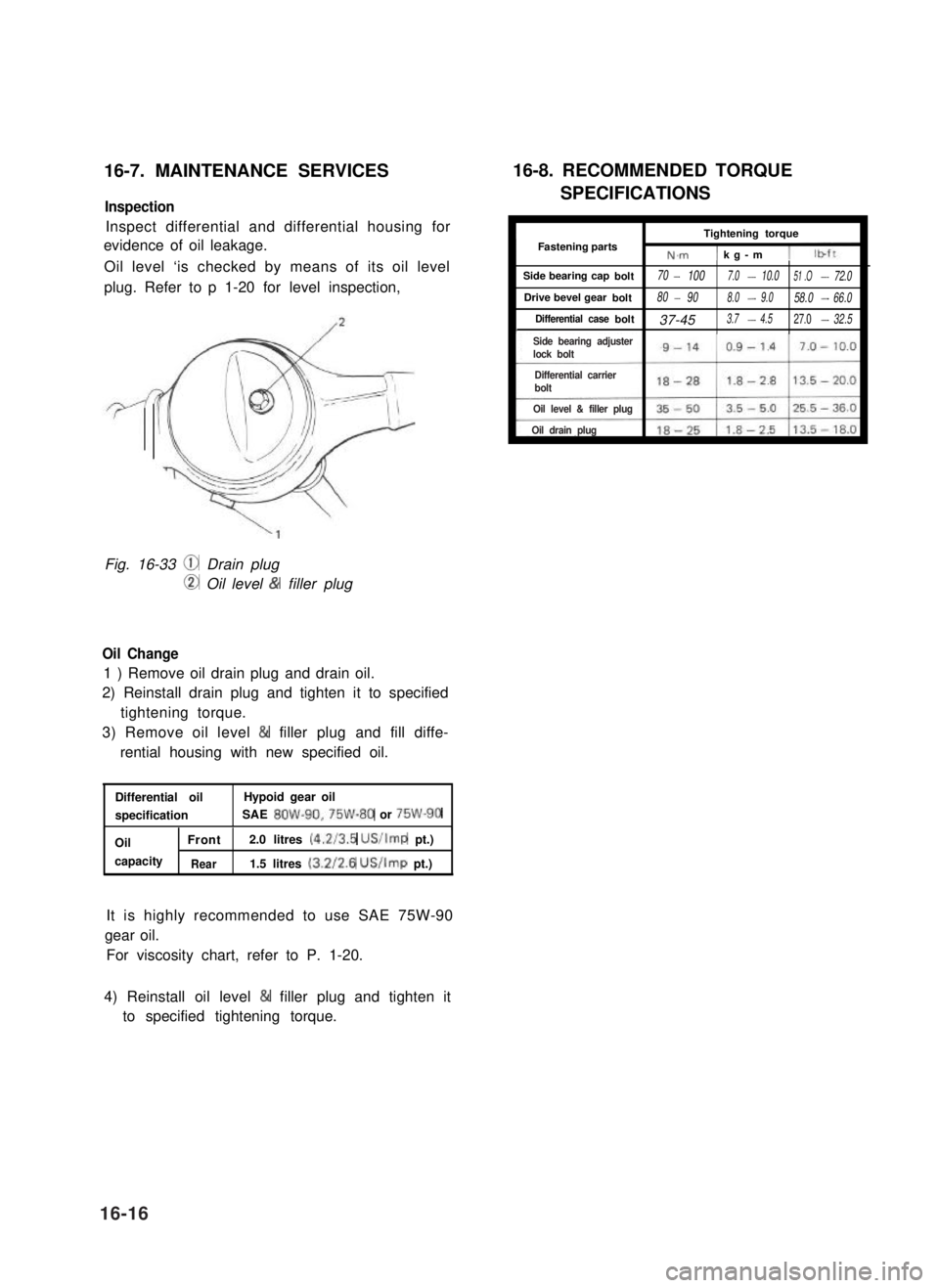
16-7. MAINTENANCE SERVICES
Inspection
Inspect differential and differential housing for
evidence of oil leakage.
Oil level ‘is checked by means of its oil level
plug. Refer to p 1-20 for level inspection,
Fig. 16-33 @ Drain plug
CD Oil level & filler plug
Oil Change
1 ) Remove oil drain plug and drain oil.
2) Reinstall drain plug and tighten it to specified
tightening torque.
3) Remove oil level & filler plug and fill diffe-
rential housing with new specified oil.
Differential oilHypoid gear oil
specificationSAE 8OW-90,75W-80 or 75W-90
OilFront2.0 litres (4.2/3.5 US/Imp pt.)
capacityRear1.5 litres (3.2/2.6 US/Imp pt.)
It is highly recommended to use SAE 75W-90
gear oil.
For viscosity chart, refer to P. 1-20.
16-8. RECOMMENDED TORQUE
SPECIFICATIONS
ITightening torqueI
IFastening partsN.m1 kg-m 11
Side bearing capbolt70- 1007.0-10.051 .O-72.0
Drive bevel gearbolt80- 908.0-9.058.0-66.0
Differential casebolt37-453.7-4.527.0-32.5I
4) Reinstall oil level & filler plug and tighten it
to specified tightening torque.
16-16
Side bearing adjusterlock bolt
Differential carrier bolt
Oil level & filler plug
Oil drain plug
Page 343 of 962
6. Remove lower and upper kingpins.
NOTE:
l Upper and lower kingpins, when removed,
must be marked off one from the other.
l Also make sure to check the number of
kingpin shims that were fitted on each side.
Front Axle Shaft Joint
1. To remove axle shaft joint, carry out steps 1
through 7 of steering knuckle removal (p.
17-8 and 17-9) and then follow steps 2 and
3 given below.
2. Drain oil from differential housing by loosen-
ing drain plug.
Fig. 17-1-23
7. Pull off steering knuckle,
NOTE:
When steering knuckle is pulled, lower king-
pin bearing sometimes falls off. So remove
bearing while pulling off the knuckle gradual-
ly.
Upper and lower kingpin bearings must be
also marked off one from the other.
Fig. 17-1-25
3. Pull axle shaft joint off front axle housing.
Fig. 17-1-26
Fig. 17-1-24
17-9