1987 SUZUKI GRAND VITARA weight
[x] Cancel search: weightPage 117 of 962

4-1. CARBURETOR
GENERAL DESCRIPTION
General
This 2-barrel downdraft type carburetor has
primary and secondary systems.
The primary system operates under normal
driving condition,and the secondary system
operates under high speed-high load driving
condition. The choke valve is provided in the
primary system.
The main components and their functions are as
follows.
The primary system has; (1) a mixture control
solenoid valve which is operated by the electri-
cal signals from the Electronic Control
Module (ECM) so as to maintain the optimum
air fuel ratio of the primary slow and the pri-
mary main systems at all times, (2) a fuel cut
solenoid valve which is for the fuel cut under
deceleration and prevention of the dieseling,
and (3) an acceleration pump system.
The secondary system has a secondary diaph-
ragm which is operated by the vacuum from
the primary side and actuates the secondary
throttle valve.
The choke system is a full automatic type
using a thermo-wax.
The switch vent solenoid valve provided on
top of the float chamber is to reduce the
evaporative emissions.
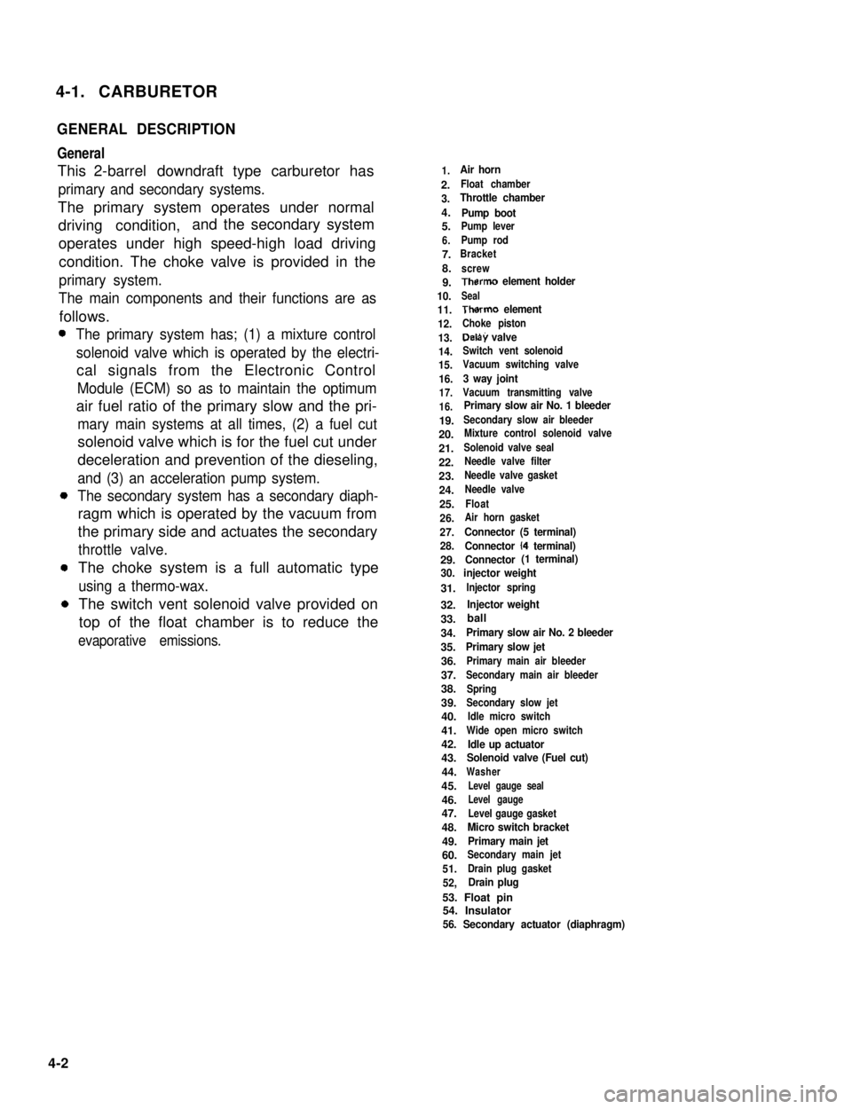
1.Air horn
2.Float chamber
3.Throttle chamber
4.Pump boot5.Pump lever
6.Pump rod
7.Bracket
8.screw
9.Therm0 element holder
10.Seal
11.Therm0 element
12.Choke piston
13.Delay valve
14.Switch vent solenoid
15.Vacuum switching valve
16.3 way joint
17.Vacuum transmitting valve
16.Primary slow air No. 1 bleeder
19.Secondary slow air bleeder
20.Mixture control solenoid valve
21.Solenoid valve seal
22.Needle valve filter
23.Needle valve gasket
24.Needle valve
25.Float
26.Air horn gasket
27.Connector (5 terminal)
28.Connector (4 terminal)
29.Connector (1 terminal)
30. injector weight
31.Injector spring
32.Injector weight
33.
34.Primary slow air No. 2 bleeder
35.Primary slow jet
36.Primary main air bleeder
37.Secondary main air bleeder
38.Spring
39.Secondary slow jet
40.Idle micro switch
41.Wide open micro switch
42.Idle up actuator43.Solenoid valve (Fuel cut)
44.Washer
45.Level gauge seal
46.Level gauge
47.Level gauge gasket
48.Micro switch bracket
49.Primary main jet
60.Secondary main jet
51.Drain plug gasket
52,Drain plug
53. Float pin54. Insulator56. Secondary actuator (diaphragm)
4-2
ball
Page 124 of 962
![SUZUKI GRAND VITARA 1987 Service Repair Manual [Secondary main system]
Operation of the secondary throttle valve is also
controlled by the VTV and VSV. When the VSV
is closed, the vacuum to be applied to the
secondary diaphragm passes the VTV side SUZUKI GRAND VITARA 1987 Service Repair Manual [Secondary main system]
Operation of the secondary throttle valve is also
controlled by the VTV and VSV. When the VSV
is closed, the vacuum to be applied to the
secondary diaphragm passes the VTV side](/manual-img/20/57437/w960_57437-123.png)
[Secondary main system]
Operation of the secondary throttle valve is also
controlled by the VTV and VSV. When the VSV
is closed, the vacuum to be applied to the
secondary diaphragm passes the VTV side and
the secondary throttle valve opens gradually.
When the primary throttle valve opens almost
fully, the VSV opens according to the signal
from the ECM. Then the vacuum is applied
directly to the secondary diaphragm and the
secondary throttle valve responds to intensity of
vacuum. When the secondary throttle valve open-
ing is wider than when secondary slow system
operates, the fuel is discharged through the
secondary main jet and mixed with the air from
the secondary main air bleeder. The air/fuel
mixture is discharged into the carburetor bore
through the main discharge hole.
1. Secondary main jet2. Secondary main air bleeder
3. Main discharge hole4. Primary throttle valve
5. Secondary throttle valve
6.Secondarydiaphragm7.VTV
8.VSV
Acceleration Pump System
This system operates to supply extra fuel to the
primary side only during the acceleration.
When the primary throttle valve closes, the
return spring pushes up the pump piston. Then
the fuel pushes up the check ball and enters into
the pump cylinder. When the throttle valve opens
during the acceleration, simultaneously the
pump piston is pushed down by means of the
pump lever. Then the fuel in the pump cylinder
pushes up the discharge ball and the lower
injector weight and discharges into the carbure-
tor bore from the pump discharge nozzle.
In this way, a higher acceleration performance is
provided by this system.
1. Primary throttle valve
2.Return spring3.Pump piston
4.Check ball6.Pump cylinder
6.Plunger7.Pump lever8.Discharge ball
9.Injector weight10. Pump discharge nozzle11. Pump damper spring
Fig. 4- l- 10Acceleration pump s ys tern
Fig. 4-l-9 Secondary main system
4-9
Page 133 of 962

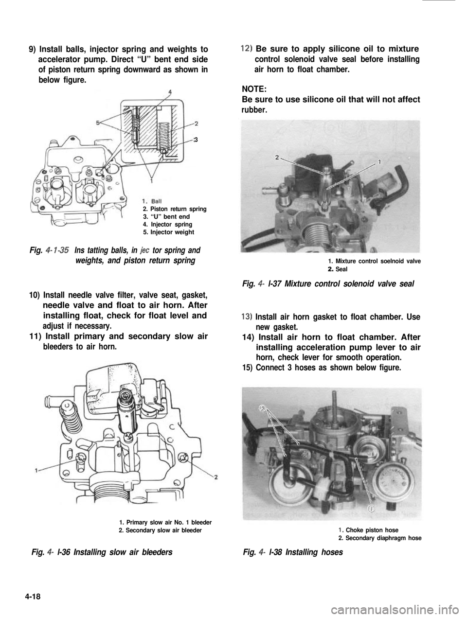
9) Install balls, injector spring and weights to
accelerator pump. Direct “U” bent end side
of piston return spring downward as shown in
below figure.
3
2. Piston return spring3. “U” bent end4. Injector spring5. Injector weight
Fig. 4- l-35Ins tatting balls, in jet tor spring and
weights, and piston return spring
10) Install needle valve filter, valve seat, gasket,
needle valve and float to air horn. After
installing float, check for float level and
adjust if necessary.
11) Install primary and secondary slow air
bleeders to air horn.
1. Primary slow air No. 1 bleeder
2. Secondary slow air bleeder
Fig. 4- l-36 Installing slow air bleeders
12) Be sure to apply silicone oil to mixture
control solenoid valve seal before installing
air horn to float chamber.
NOTE:
Be sure to use silicone oil that will not affect
rubber.
1. Mixture control soelnoid valve
2. Seal
Fig. 4- l-37 Mixture control solenoid valve seal
13) Install air horn gasket to float chamber. Use
new gasket.
14) Install air horn to float chamber. After
installing acceleration pump lever to air
horn, check lever for smooth operation.
15) Connect 3 hoses as shown below figure.
I, Choke piston hose
2. Secondary diaphragm hose
Fig. 4- l-38 Installing hoses
4-18
Page 135 of 962

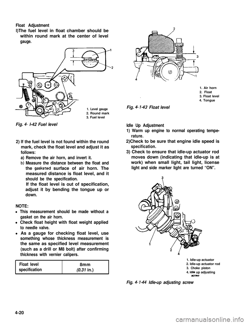
Float Adjustment
l)The fuel level in float chamber should be
within round mark at the center of level
gauge.
1. Level gauge
2. Round mark3. Fuel level
Fig. 4- l-42 Fuel level
2) If the fuel level is not found within the round
mark, check the float level and adjust it as
follows:
a) Remove the air horn, and invert it.
b) Measure the distance between the float and
the gasketed surface of air horn. The
measured distance is float level, and it
should be the specification.
If the float level is out of specification,
adjust it by bending the tongue up or
down.
NOTE:
l This measurement should be made without a
gasket on the air horn.
l Check float height with float weight applied
to needle valve.
l As a gauge for checking float level, use
something whose thickness measurement is
the same as specified level measurement
(such as a drill or M8 bolt) after confirming
thickness with vernier calipers.
Float level8mm
specification(0.31 in.)
.
Fig. 4- l-43 Float level
1. Air horn
2. Float
3. Float level
4. Tongue
Idle Up Adjustment
1) Warm up engine to normal operating tempe-
rature.
2)Check to be sure that engine idle speed is
specification.
3) Check to ensure that idle-up actuator rod
moves down (indicating that idle-up is at
work) when small light, tail light, license
light and side marker light are turned “ON”.
1. Idle-up actuator
2. Idle-up actuator rod
3. Choke piston
4. Idle up adjustingsorew
Fig. 4- l-44 Idle-up adjusting screw
4-20
Page 213 of 962

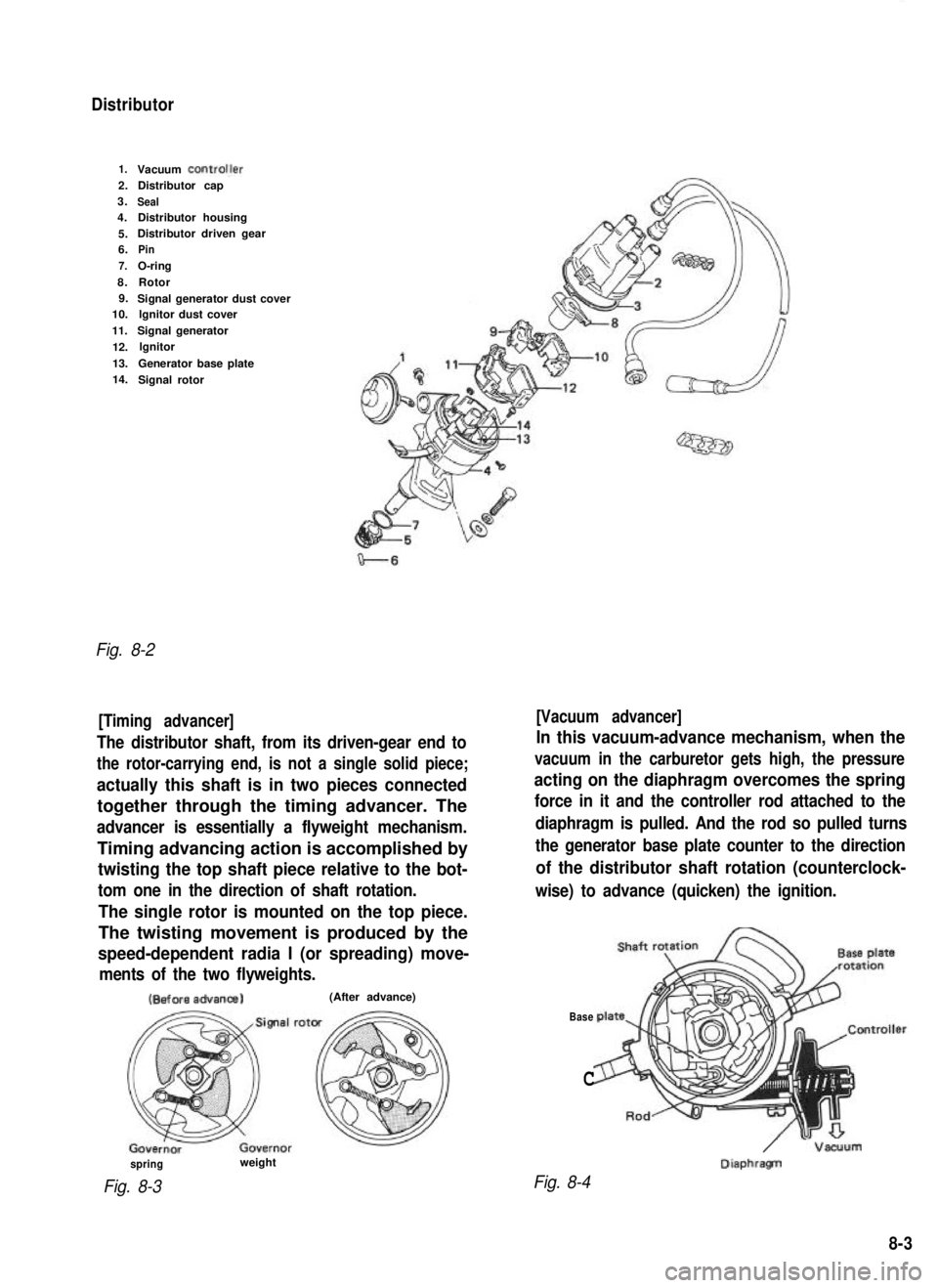
Distributor
1.Vacuum ControlJer2.Distributor cap
3.
Seal4. Distributor housing
5. Distributor driven gear
6.
Pin
7.
O-ring
8. Rotor
9. Signal generator dust cover
10. lgnitor dust cover
11. Signal generator
12. lgnitor
13. Generator base plate
14. Signal rotor
Fig. 8-2
[Timing advancer] [Vacuum advancer]
The distributor shaft, from its driven-gear end to
the rotor-carrying end, is not a single solid piece;
actually this shaft is in two pieces connected
together through the timing advancer. The
advancer is essentially a flyweight mechanism.
Timing advancing action is accomplished by
twisting the top shaft piece relative to the bot-
tom one in the direction of shaft rotation.
The single rotor is mounted on the top piece.
The twisting movement is produced by the
speed-dependent radia I (or spreading) move-
ments of the two flyweights.
In this vacuum-advance mechanism, when the
vacuum in the carburetor gets high, the pressure
acting on the diaphragm overcomes the spring
force in it and the controller rod attached to the
diaphragm is pulled. And the rod so pulled turns
the generator base plate counter to the direction
of the distributor shaft rotation (counterclock-
wise) to advance (quicken) the ignition. (Before
advanca)
(After advance)
Base
C
/ -Vacuum DiaphragTI
spring
Fig. 8-3
weight
Fig. 8-4
8-3