1987 SUZUKI GRAND VITARA wiring
[x] Cancel search: wiringPage 20 of 962
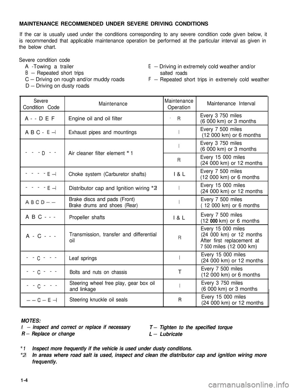
MAINTENANCE RECOMMENDED UNDER SEVERE DRIVING CONDITIONS
If the car is usually used under the conditions corresponding to any severe condition code given below, it
is recommended that applicable maintenance operation be performed at the particular interval as given in
the below chart.
Severe condition code
A -Towing a trailer
B- Repeated short trips
C - Driving on rough and/or muddy roads
D - Driving on dusty roads
E- Driving in extremely cold weather and/or
salted roads
F- Repeated short trips in extremely cold weather
Severe
Condition CodeMaintenanceMaintenance
OperationMaintenance Interval
A--DEFEngine oil and oil filter_ REvery 3 750 miles
(6 000 km) or 3 months
ABC- E-Exhaust pipes and mountingsIEvery 7 500 miles
(12 000 km) or 6 months
IEvery 3 750 miles
D(6 000 km) or 3 months--- --Air cleaner filter element * 1
REvery 15 000 miles
(24 000 km) or 12 months
----E-Choke system (Carburetor shafts)I&LEvery 7 500 miles
(12 000 km) or 6 months
----E-Distributor cap and Ignition wiring “2IEvery 15 000 miles
(24 000 km) or 12 months
ABCD--Brake discs and pads (Front)IEvery 7 500 miles
Brake drums and shoes (Rear)( 12 000 km) or 6 months
ABC---Propeller shaftsI&LEvery 7 500 miles
(12 000 km) or 6 months
Every 15 000 miles
A-C---Transmission, transfer and differential(24 000 km) or 12 months
oilRAfter first replacement at
7 500 miles (12 000 km)
CEvery 15 000 miles-- ---’ Leaf springsI(24 000 km) or 12 months
C-- ---Bolts and nuts on chassisTEvery 7 500 miles
(12 000 km) or 6 months
CSteering wheel free play, gear box oil-- ---and linkageIEvery 3 750 miles
(6 000 km) or 3 months
--C-E-Steering knuckle oil sealsREvery 15 000 miles
(24 000 km) or 12 months
MOTES:
I- inspect and correct or replace if necessary
R - Replace or change
T - Tighten to the specified torque
L - Lubricate
* 1Inspect more frequently if the vehicle is used under dusty conditions.
*2In areas where road salt is used, inspect and clean the distributor cap and ignition wiring more
frequently.
1-4
Page 28 of 962
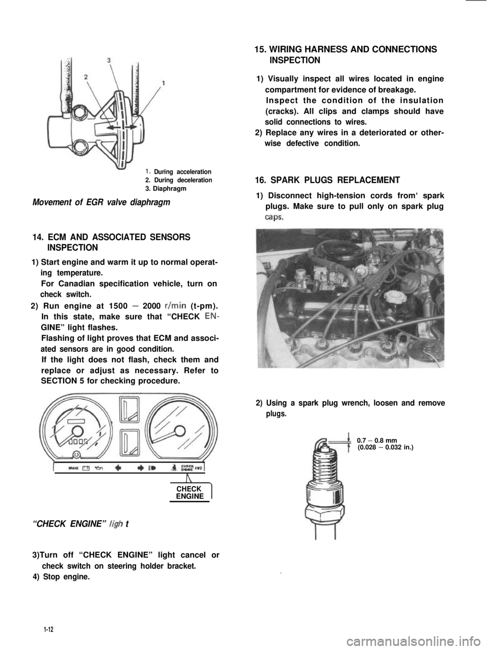
1. During acceleration
2. During deceleration
3. Diaphragm
Movement of EGR valve diaphragm
14. ECM AND ASSOCIATED SENSORS
INSPECTION
1) Start engine and warm it up to normal operat-
ing temperature.
For Canadian specification vehicle, turn on
check switch.
2) Run engine at 1500 - 2000 r/min (t-pm).
In this state, make sure that “CHECK EON-
GINE” light flashes.
Flashing of light proves that ECM and associ-
ated sensors are in good condition.
If the light does not flash, check them and
replace or adjust as necessary. Refer to
SECTION 5 for checking procedure.
A
CHECKENGINE
“CHECK ENGINE” ligh t
3)Turn off “CHECK ENGINE” light cancel or
check switch on steering holder bracket.
4) Stop engine.
15. WIRING HARNESS AND CONNECTIONS
INSPECTION
1) Visually inspect all wires located in engine
compartment for evidence of breakage.
Inspect the condition of the insulation
(cracks). All clips and clamps should have
solid connections to wires.
2) Replace any wires in a deteriorated or other-
wise defective condition.
16. SPARK PLUGS REPLACEMENT
1) Disconnect high-tension cords from‘ spark
plugs. Make sure to pull only on spark plug
caps.
2) Using a spark plug wrench, loosen and remove
plugs.
0.7 - 0.8 mm(0.028 - 0.032 in.)
1-12
Page 29 of 962
NOTE:
When replacing plugs, make sure to use new
plugs of specified heat range and size.
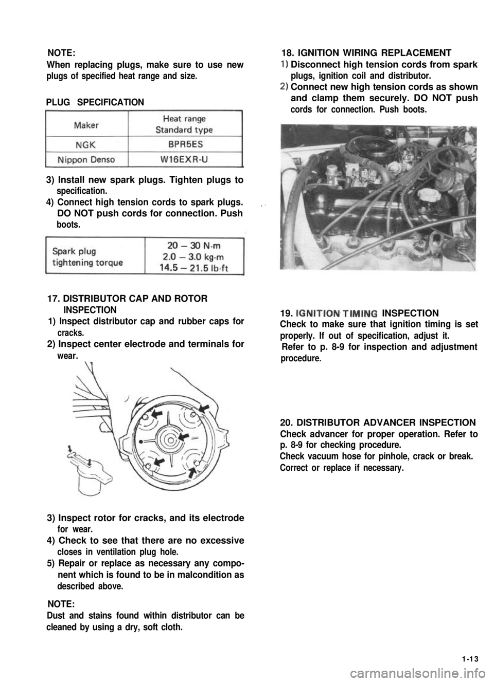
PLUG SPECIFICATION
~1
3) Install new spark plugs. Tighten plugs to
specification.
4) Connect high tension cords to spark plugs.
DO NOT push cords for connection. Push
boots.
17. DISTRIBUTOR CAP AND ROTOR
INSPECTION
1) Inspect distributor cap and rubber caps for
cracks.
2) Inspect center electrode and terminals for
wear.\‘(
3) Inspect rotor for cracks, and its electrode
for wear.
4) Check to see that there are no excessive
closes in ventilation plug hole.
5) Repair or replace as necessary any compo-
nent which is found to be in malcondition as
described above.
18. IGNITION WIRING REPLACEMENT
1) Disconnect high tension cords from spark
plugs, ignition coil and distributor.
2) Connect new high tension cords as shown
and clamp them securely. DO NOT push
cords for connection. Push boots.
19. IGNITION~TIMING INSPECTION
Check to make sure that ignition timing is set
properly. If out of specification, adjust it.
Refer to p. 8-9 for inspection and adjustment
procedure.
20. DISTRIBUTOR ADVANCER INSPECTION
Check advancer for proper operation. Refer to
p. 8-9 for checking procedure.
Check vacuum hose for pinhole, crack or break.
Correct or replace if necessary.
NOTE:
Dust and stains found within distributor can be
cleaned by using a dry, soft cloth.
1-13
Page 55 of 962

Condition
Starter will not run
at all, or runs but
runs too slow to
crank with full
force
Starter does not
stop running.
2-11. ALTERNATOR
Condition
Battery quickly
becomes over-
discharged.
Charge light does not
light with ignition ON
and engine off
Alternator noise
Possible cause
Magnet switch trouble
1. Lead wire socket loose in place
2. Burnt contact plate, or poor contacting
action
3. Open-circuit in pull-in coil
4. Open-circuit in holding coil
Starter proper trouble
1. Brushes seating poorly or worn down
2. Burnt commutator
3. Open-circuit in armature winding
4. Worn-down starter.
1. Fused contact points of magnet-switch
contact plate
2. Short-circuit between turns of magnet-
switch coil (layer short-circuit)
3. Failure of returning action in ignition
switch
Possible cause
1. Loose or broken “V” belt
2. Battery cables loose, corroded or worn
3. Low level of battery electrolyte
4. Defective battery cell plates
5. Insufficient contact in battery terminal
connection.
6. Excessive electrical load
7. IC regulator or alternator faulty
8. Defective idle up system
1. Fuse blown
2. Light burned out
3. Loose wiring connection
4. IC regulator faulty
1. Worn, loose or otherwise defective bearings
Correction
Retighten
Replace, or repair
Replace
Replace
Repair or replace
Repair or replace
Replace
Replace
Repair or replace
Replace
Replace
Correction
Adjust or replace
Repair or replcae
Replace
Replace the battery
Clean and retighten
Check charging system
Replace
Repair or replace
Check fuse
Replace light
Tighten loose connection!
Replace
i
Replace
2-17
Page 173 of 962
[Jet1
1) Remove jet.
2) When blowing air into pipe 0, air should
come out of pipe 0.
Replace clogged jet.
3) Install jet with its gray side directed toward
MCV.
1. Pipe (Gray side)2.Pipe
33.Jet
Fig.53-134.Blowair
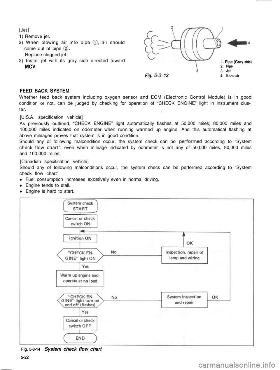
FEED BACK SYSTEM
Whether feed back system including oxygen sensor and ECM (Electronic Control Module) is in good
condition or not, can be judged by checking for operation of “CHECK ENGINE” light in instrument clus-
ter..
[U.S.A. specification vehicle]
As previously outlined,“CHECK ENGINE” light automatically flashes at 50,000 miles, 80,000 miles and
100,000 miles indicated on odometer when running warmed up engine. And this automatical flashing at
above mileages proves that system is in good condition.
Should any of following malcondition occur, the system check can be .performed according to “System
check flow chart”,even when mileage indicated by odometer is not any of 50,000 miles, 80,000 miles
and 100,000 miles.
[Canadian specification vehicle]
Should any of following malconditions occur, the system check can be performed according to “System
check flow chart”.
l Fuel consumption increases excssively even in normal driving.
l Engine tends to stall.
l Engine is hard to start.
System check
STARTI
Cancel or check
switch ON
“CHECK EN-
Yes
Inspection, repair of
lamp and wiring1
Warm up engine and
operate at no load
I
“CHECK EN-GINE”light turnonand off (flashes)I
NoSystem inspection OK
and repair
Cancel or check
Fig. 5-3-14System check flow chart
5-22
Page 180 of 962
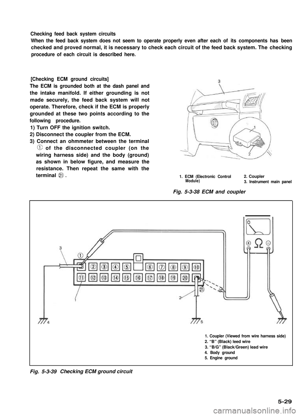
Checking feed back system circuits
When the feed back system does not seem to operate properly even after each of its components has been
checked and proved normal, it is necessary to check each circuit of the feed back system. The checking
procedure of each circuit is described here.
[Checking ECM ground circuits]
The ECM is grounded both at the dash panel and
the intake manifold. If either grounding is not
made securely, the feed back system will not
operate. Therefore, check if the ECM is properly
grounded at these two points according to the
following procedure.
1) Turn OFF the ignition switch.
2) Disconnect the coupler from the ECM.
3) Connect an ohmmeter between the terminal
@ of the disconnected coupler (on the
wiring harness side) and the body (ground)
as shown in below figure, and measure the
resistance. Then repeat the same with the
terminal 0.1. ECM (Electronic Control2. CouplerModule)3. Instrument main panel
Fig. 5-3-38 ECM and coupler
1. Coupler (Viewed from wire harness side)
2. “B” (Black) leed wire
3. “B/G” (Black/Green) lead wire
4. Body ground
5. Engine ground
Fig. 5-3-39Checking ECM ground circuit
5-29
Page 182 of 962
![SUZUKI GRAND VITARA 1987 Service Repair Manual [Checking ECM power circuits]
Connected to the ECM are the ignition coil and solenoids or solenoid valves. If a disconnection or a
failure of contact occurs within a circuit (power circuit) including SUZUKI GRAND VITARA 1987 Service Repair Manual [Checking ECM power circuits]
Connected to the ECM are the ignition coil and solenoids or solenoid valves. If a disconnection or a
failure of contact occurs within a circuit (power circuit) including](/manual-img/20/57437/w960_57437-181.png)
[Checking ECM power circuits]
Connected to the ECM are the ignition coil and solenoids or solenoid valves. If a disconnection or a
failure of contact occurs within a circuit (power circuit) including any of these coil or solenoids or sole-
noid valves, signals will not be sent to the ECM and as a result, the feed back system will not operate
properly. Therefore, check the power circuits according to the following procedure.
1) Disconnect the coupler connected to the ECM.
2) Turn ON the ignition switch but be sure not to run the engine.
3) Connect a voltmeter between the terminal @ of the disconnected coupler (on the wiring harness side)
and the body (ground) as shown in below figure and measure the voltage. And then repeat the same
with each of the terminals 0, 0, 0, 0, 8, @ and 0. If the measured voltage between each
terminal and the body is about 12V, each circuit is in good condition.
4) If about 12V is not obtained in the above check, the particular circuit may be disconnected or out of
contact. Check the circuit for such conditions.
5) After checking, connect the coupler to ECM securely..
1. Coupler (Viewed from wire harness side)10. Three way solenoid valve (EGR system)
2. Battery11. Br (Brown) lead wire
3. Ignition switch (ON)!2. BI/R (Blue/Red) lead wire
4. Ignition coil13. B/W (Black/White) lead wire
5. Vacuum switching valve14. Br/W (Brown/White) lead wire(secondary throttle valve)15. BI/B (Blue/Black) lead wire6. Three way solenoid valve (Idle-up)16. BI/Y (Blue/Yellow) lead wire7. Mixture control solenoid17. BI/W (Blue/White) lead wire8. Switch vent solenoid18. BllG (Blue/Green) lead wire9. Fuel cut solenoid valve
Fig. 5-3-42 Checking ECM power circuits
Page 212 of 962
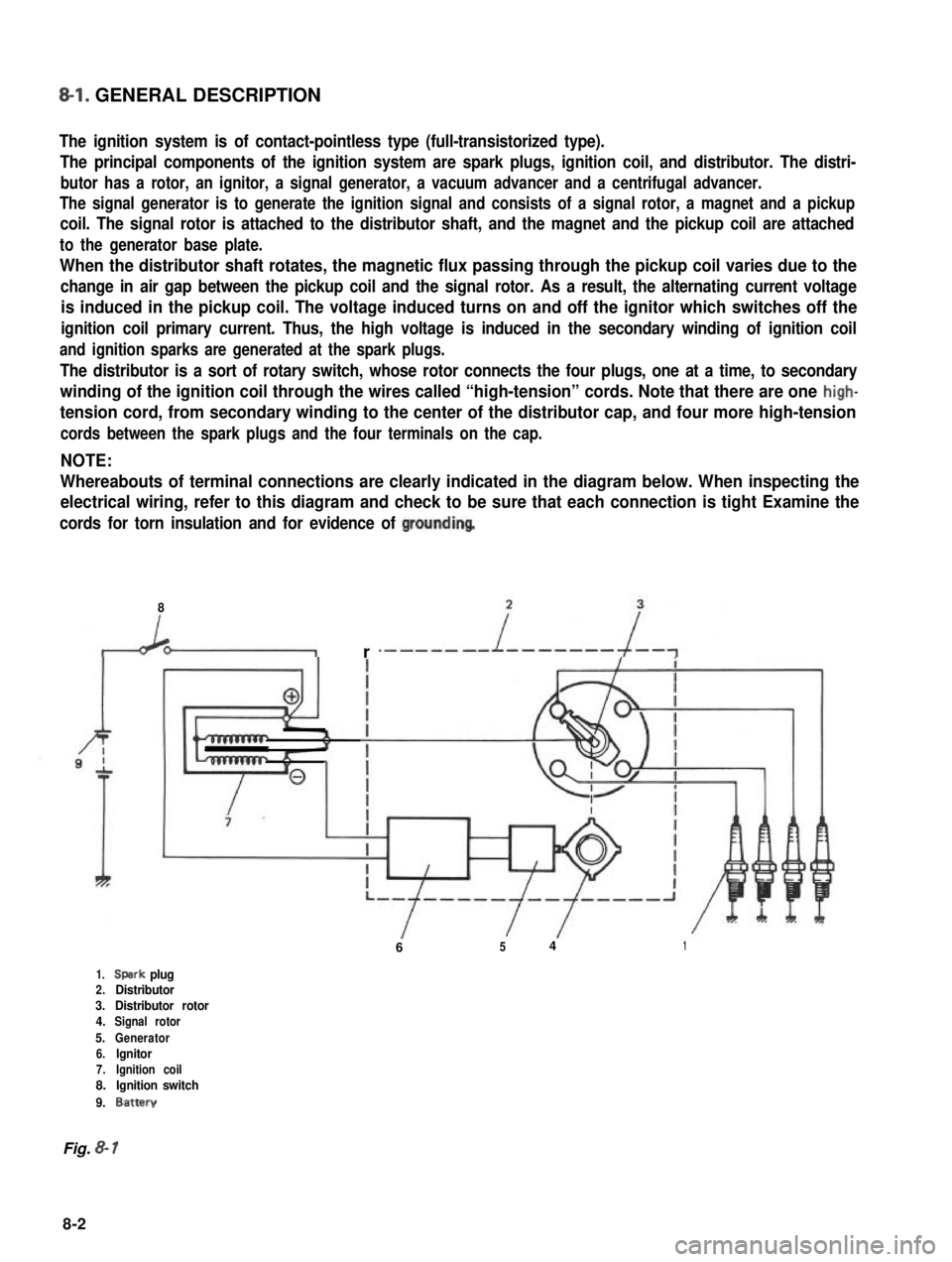
8-l. GENERAL DESCRIPTION
The ignition system is of contact-pointless type (full-transistorized type).
The principal components of the ignition system are spark plugs, ignition coil, and distributor. The distri-
butor has a rotor, an ignitor, a signal generator, a vacuum advancer and a centrifugal advancer.
The signal generator is to generate the ignition signal and consists of a signal rotor, a magnet and a pickup
coil. The signal rotor is attached to the distributor shaft, and the magnet and the pickup coil are attached
to the generator base plate.
When the distributor shaft rotates, the magnetic flux passing through the pickup coil varies due to the
change in air gap between the pickup coil and the signal rotor. As a result, the alternating current voltage
is induced in the pickup coil. The voltage induced turns on and off the ignitor which switches off the
ignition coil primary current. Thus, the high voltage is induced in the secondary winding of ignition coil
and ignition sparks are generated at the spark plugs.
The distributor is a sort of rotary switch, whose rotor connects the four plugs, one at a time, to secondary
winding of the ignition coil through the wires called “high-tension” cords. Note that there are one high-
tension cord, from secondary winding to the center of the distributor cap, and four more high-tension
cords between the spark plugs and the four terminals on the cap.
NOTE:
Whereabouts of terminal connections are clearly indicated in the diagram below. When inspecting the
electrical wiring, refer to this diagram and check to be sure that each connection is tight Examine the
cords for torn insulation and for evidence of groundinq
8
r
6541
1.Spark plug2.Distributor3.Distributor rotor4.Signal rotor
5.Generator6.lgnitor7.Ignition coil8.Ignition switch
9.Battery
Fig. 8- 1
8-2