1987 SUZUKI GRAND VITARA turn signal
[x] Cancel search: turn signalPage 121 of 962
![SUZUKI GRAND VITARA 1987 Service Repair Manual [Switch vent solenoid]
Provided on top of the float chamber is a switch
vent solenoid which is connected to the ignition
switch through ECM. As the ignition switch is
operated, the solenoid opens and SUZUKI GRAND VITARA 1987 Service Repair Manual [Switch vent solenoid]
Provided on top of the float chamber is a switch
vent solenoid which is connected to the ignition
switch through ECM. As the ignition switch is
operated, the solenoid opens and](/manual-img/20/57437/w960_57437-120.png)
[Switch vent solenoid]
Provided on top of the float chamber is a switch
vent solenoid which is connected to the ignition
switch through ECM. As the ignition switch is
operated, the solenoid opens and closes its valve
so as not to release the fuel vapor in the float
chamber out into the atmosphere.
When the ignition switch is turned to “OFF”
position, the passage connecting the inner vent
passage and the float chamber will close, and the
passage connecting the float chamber and the
canister will open, then the fuel vapor will flow
into the canister.
When the ignition switch is turned to “ON”
position, and engine speed is above 400 r/min,
the passage connecting the float chamber and
the canister will close, and the passage connect-
ing the float chamber and the inner vent passage
will open, then the fuel vapor will flow into the
carburetor bore.
1. Switch vent solenoid
2. Float
3. To canister
4. Inner vent passage
Fig. 4- l-4 Switch vent solenoid
Primary System
[Primary slow system]
The fuel, after passing through the main jet, is
metered by the primary slow jet, then mixed
with the air from the primary slow air No. 2
bleeder. This air/fuel mixture is further blended
with the air from the primary slow air No. 1
bleeder and air supplied through the mixture
control solenoid. Then the air/fuel mixture
passes through the idle down channel and enters
the carburetor bore through the off idle discharge
port and the idle discharge hole.
[Mixture control solenoid valve]
The primary system has the Mixture Control
Solenoid (MCS) Valve. In the MCS, there is a
plunger which makes 16 up and down move-
ments per second by the electrical signals from
the Electronic Control Module (ECM). That is,
when an electrical signal is received by the
solenoid, the plunger will move down and when
no signal is received, the plunger will move up
by the spring force.
When the plunger moves down, the air jet locat-
ed on the upper side of the mixture control
solenoid valve will open as shown in below
figure, allowing the air to flow into the idle
down channel. In this condition, the mixture
will become lean.
On the other hand, when the plunger is pushed
up by the spring, the air jet will close, shutting
off the air flow into the idle down channel. In
this condition, the mixture will become rich.
The up and down movement of the plunger at
the rate of 16 times per second to the signals
from the ECM controls the air/fuel mixture to
the optimum ratio at all times and as a result
helps to improve the emission and engine per-
formances, and fuel economy.
The ECM receives the electrical information
from the oxygen sensor installed to the exhaust
manifold and the engine operating condition
signals from other devices and sends out and
stops the electrical signal to the mixture control
solenoid valve to actuate the plunger up and
down 16 times every second. The ECM is locat-
ed under the glove box of the instrument panel.
4-6
Page 124 of 962
![SUZUKI GRAND VITARA 1987 Service Repair Manual [Secondary main system]
Operation of the secondary throttle valve is also
controlled by the VTV and VSV. When the VSV
is closed, the vacuum to be applied to the
secondary diaphragm passes the VTV side SUZUKI GRAND VITARA 1987 Service Repair Manual [Secondary main system]
Operation of the secondary throttle valve is also
controlled by the VTV and VSV. When the VSV
is closed, the vacuum to be applied to the
secondary diaphragm passes the VTV side](/manual-img/20/57437/w960_57437-123.png)
[Secondary main system]
Operation of the secondary throttle valve is also
controlled by the VTV and VSV. When the VSV
is closed, the vacuum to be applied to the
secondary diaphragm passes the VTV side and
the secondary throttle valve opens gradually.
When the primary throttle valve opens almost
fully, the VSV opens according to the signal
from the ECM. Then the vacuum is applied
directly to the secondary diaphragm and the
secondary throttle valve responds to intensity of
vacuum. When the secondary throttle valve open-
ing is wider than when secondary slow system
operates, the fuel is discharged through the
secondary main jet and mixed with the air from
the secondary main air bleeder. The air/fuel
mixture is discharged into the carburetor bore
through the main discharge hole.
1. Secondary main jet2. Secondary main air bleeder
3. Main discharge hole4. Primary throttle valve
5. Secondary throttle valve
6.Secondarydiaphragm7.VTV
8.VSV
Acceleration Pump System
This system operates to supply extra fuel to the
primary side only during the acceleration.
When the primary throttle valve closes, the
return spring pushes up the pump piston. Then
the fuel pushes up the check ball and enters into
the pump cylinder. When the throttle valve opens
during the acceleration, simultaneously the
pump piston is pushed down by means of the
pump lever. Then the fuel in the pump cylinder
pushes up the discharge ball and the lower
injector weight and discharges into the carbure-
tor bore from the pump discharge nozzle.
In this way, a higher acceleration performance is
provided by this system.
1. Primary throttle valve
2.Return spring3.Pump piston
4.Check ball6.Pump cylinder
6.Plunger7.Pump lever8.Discharge ball
9.Injector weight10. Pump discharge nozzle11. Pump damper spring
Fig. 4- l- 10Acceleration pump s ys tern
Fig. 4-l-9 Secondary main system
4-9
Page 136 of 962

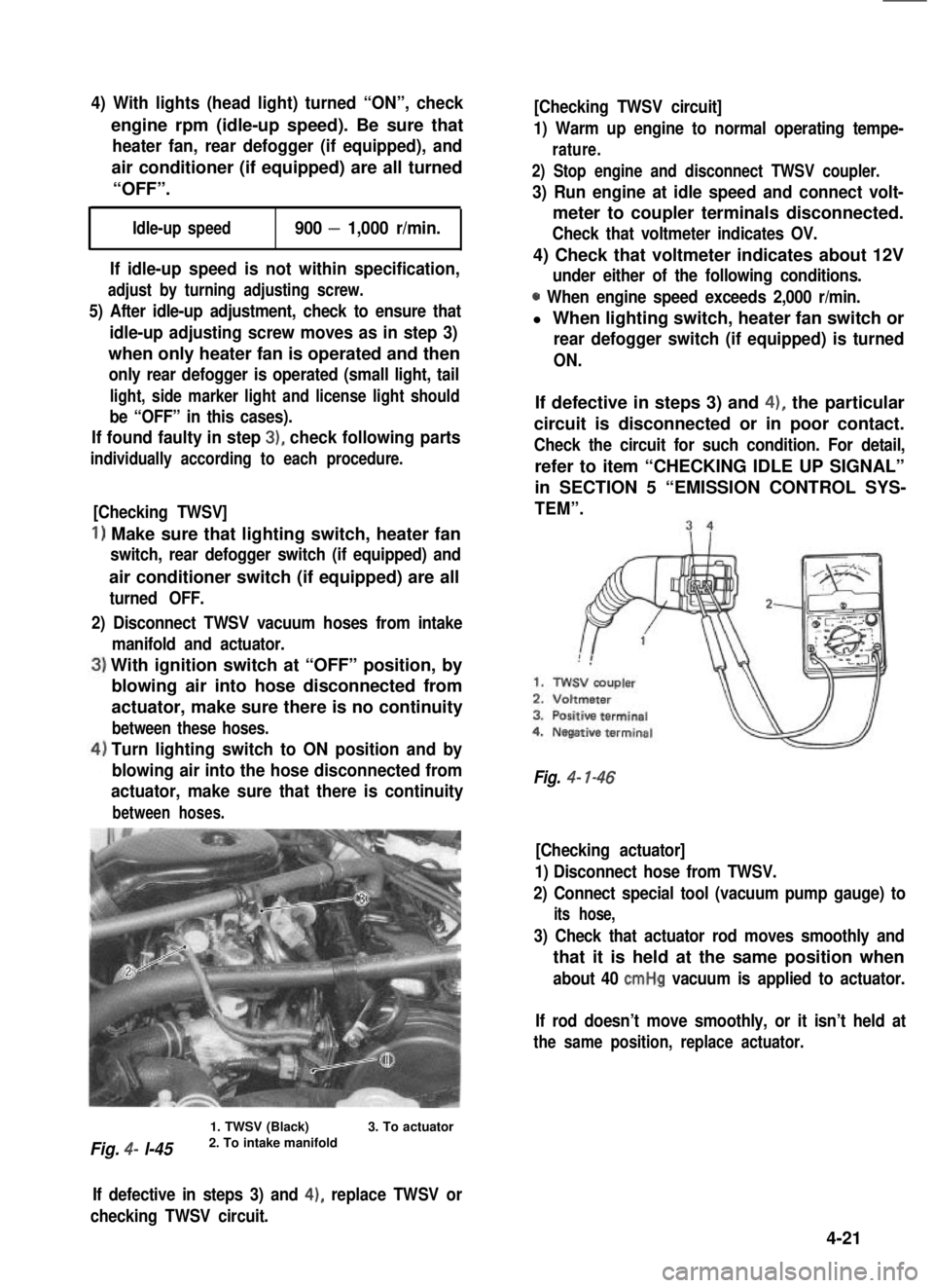
4) With lights (head light) turned “ON”, check
engine rpm (idle-up speed). Be sure that
heater fan, rear defogger (if equipped), and
air conditioner (if equipped) are all turned
“OFF”.
Idle-up speed900 - 1,000 r/min.
If idle-up speed is not within specification,
adjust by turning adjusting screw.
5) After idle-up adjustment, check to ensure that
idle-up adjusting screw moves as in step 3)
when only heater fan is operated and then
only rear defogger is operated (small light, tail
light, side marker light and license light should
be “OFF” in this cases).
If found faulty in step 3), check following parts
individually according to each procedure.
[Checking TWSV]
1) Make sure that lighting switch, heater fan
switch, rear defogger switch (if equipped) and
air conditioner switch (if equipped) are all
turned OFF.
2) Disconnect TWSV vacuum hoses from intake
manifold and actuator.
With ignition switch at “OFF” position, by
blowing air into hose disconnected from
actuator, make sure there is no continuity
between these hoses.
Turn lighting switch to ON position and by
blowing air into the hose disconnected from
actuator, make sure that there is continuity
between hoses.
Fig. 4- l-45
1. TWSV (Black)2. To intake manifold3. To actuator
[Checking TWSV circuit]
1) Warm up engine to normal operating tempe-
rature.
2) Stop engine and disconnect TWSV coupler.
3) Run engine at idle speed and connect volt-
meter to coupler terminals disconnected.
Check that voltmeter indicates OV.
4) Check that voltmeter indicates about 12V
under either of the following conditions.
0 When engine speed exceeds 2,000 r/min.
l When lighting switch, heater fan switch or
rear defogger switch (if equipped) is turned
ON.
If defective in steps 3) and 4), the particular
circuit is disconnected or in poor contact.
Check the circuit for such condition. For detail,
refer to item “CHECKING IDLE UP SIGNAL”
in SECTION 5 “EMISSION CONTROL SYS-
TEM”.
Fig. 4- l-46
[Checking actuator]
1) Disconnect hose from TWSV.
2) Connect special tool (vacuum pump gauge) to
its hose,
3) Check that actuator rod moves smoothly and
that it is held at the same position when
about 40 cmHg vacuum is applied to actuator.
If rod doesn’t move smoothly, or it isn’t held at
the same position, replace actuator.
If defective in steps 3) and 4), replace TWSV or
checking TWSV circuit.
4-21
Page 163 of 962

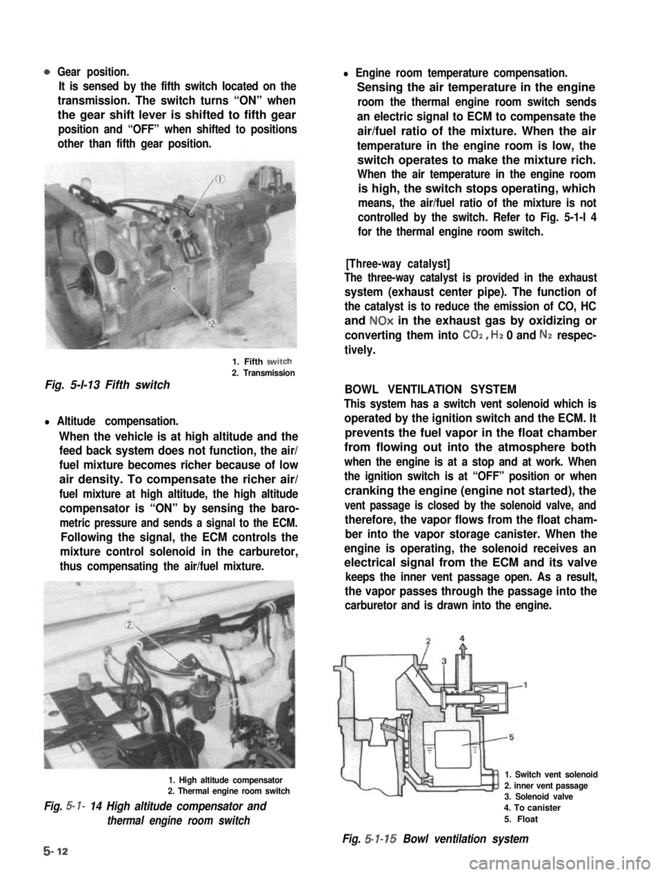
Gear position.
It is sensed by the fifth switch located on the
transmission. The switch turns “ON” when
the gear shift lever is shifted to fifth gear
position and “OFF” when shifted to positions
other than fifth gear position.
1. Fifth swirch
2. Transmission
Fig. 5-l-13 Fifth switch
l Altitude compensation.
When the vehicle is at high altitude and the
feed back system does not function, the air/
fuel mixture becomes richer because of low
air density. To compensate the richer air/
fuel mixture at high altitude, the high altitude
compensator is “ON” by sensing the baro-
metric pressure and sends a signal to the ECM.
Following the signal, the ECM controls the
mixture control solenoid in the carburetor,
thus compensating the air/fuel mixture.
1. High altitude compensator2. Thermal engine room switch
Fig. 5- I- 14 High altitude compensator and
thermal engine room switch
l Engine room temperature compensation.
Sensing the air temperature in the engine
room the thermal engine room switch sends
an electric signal to ECM to compensate the
air/fuel ratio of the mixture. When the air
temperature in the engine room is low, the
switch operates to make the mixture rich.
When the air temperature in the engine room
is high, the switch stops operating, which
means, the air/fuel ratio of the mixture is not
controlled by the switch. Refer to Fig. 5-1-l 4
for the thermal engine room switch.
[Three-way catalyst]
The three-way catalyst is provided in the exhaust
system (exhaust center pipe). The function of
the catalyst is to reduce the emission of CO, HC
and NOx in the exhaust gas by oxidizing or
converting them into CO2, Hz 0 and Nz respec-
tively.
BOWL VENTILATION SYSTEM
This system has a switch vent solenoid which is
operated by the ignition switch and the ECM. It
prevents the fuel vapor in the float chamber
from flowing out into the atmosphere both
when the engine is at a stop and at work. When
the ignition switch is at “OFF” position or when
cranking the engine (engine not started), the
vent passage is closed by the solenoid valve, and
therefore, the vapor flows from the float cham-
ber into the vapor storage canister. When the
engine is operating, the solenoid receives an
electrical signal from the ECM and its valve
keeps the inner vent passage open. As a result,
the vapor passes through the passage into the
carburetor and is drawn into the engine.
1. Switch vent solenoid
2. inner vent passage3. Solenoid valve
4. To canister
5. Float
Fig. 5-l-15 Bowl ventilation system
5-12
Page 164 of 962

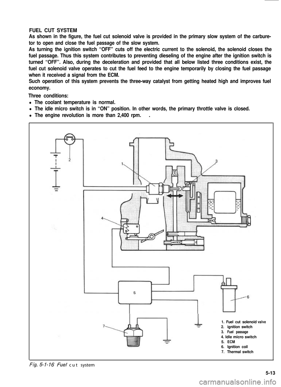
FUEL CUT SYSTEM
As shown in the figure, the fuel cut solenoid valve is provided in the primary slow system of the carbure-
tor to open and close the fuel passage of the slow system.
As turning the ignition switch “OFF” cuts off the electric current to the solenoid, the solenoid closes the
fuel passage. Thus this system contributes to preventing dieseling of the engine after the ignition switch is
turned “OFF”. Also, during the deceleration and provided that all below listed three conditions exist, the
fuel cut solenoid valve operates to cut the fuel feed to the engine temporarily by closing the fuel passage
when it received a signal from the ECM.
Such operation of this system prevents the three-way catalyst from getting heated high and improves fuel
economy.
Three conditions:
l The coolant temperature is normal.
l The idle micro switch is in “ON” position. In other words, the primary throttle valve is closed.
l The engine revolution is more than 2,400 rpm..
1. Fuel cut solenoid
2.ignition switch
3.Fuel passage
4. Idle micro switch
5.ECM
6.Ignition coil
7.Thermal switch
valve
-. .t/g. cut system
5-13
Page 182 of 962
![SUZUKI GRAND VITARA 1987 Service Repair Manual [Checking ECM power circuits]
Connected to the ECM are the ignition coil and solenoids or solenoid valves. If a disconnection or a
failure of contact occurs within a circuit (power circuit) including SUZUKI GRAND VITARA 1987 Service Repair Manual [Checking ECM power circuits]
Connected to the ECM are the ignition coil and solenoids or solenoid valves. If a disconnection or a
failure of contact occurs within a circuit (power circuit) including](/manual-img/20/57437/w960_57437-181.png)
[Checking ECM power circuits]
Connected to the ECM are the ignition coil and solenoids or solenoid valves. If a disconnection or a
failure of contact occurs within a circuit (power circuit) including any of these coil or solenoids or sole-
noid valves, signals will not be sent to the ECM and as a result, the feed back system will not operate
properly. Therefore, check the power circuits according to the following procedure.
1) Disconnect the coupler connected to the ECM.
2) Turn ON the ignition switch but be sure not to run the engine.
3) Connect a voltmeter between the terminal @ of the disconnected coupler (on the wiring harness side)
and the body (ground) as shown in below figure and measure the voltage. And then repeat the same
with each of the terminals 0, 0, 0, 0, 8, @ and 0. If the measured voltage between each
terminal and the body is about 12V, each circuit is in good condition.
4) If about 12V is not obtained in the above check, the particular circuit may be disconnected or out of
contact. Check the circuit for such conditions.
5) After checking, connect the coupler to ECM securely..
1. Coupler (Viewed from wire harness side)10. Three way solenoid valve (EGR system)
2. Battery11. Br (Brown) lead wire
3. Ignition switch (ON)!2. BI/R (Blue/Red) lead wire
4. Ignition coil13. B/W (Black/White) lead wire
5. Vacuum switching valve14. Br/W (Brown/White) lead wire(secondary throttle valve)15. BI/B (Blue/Black) lead wire6. Three way solenoid valve (Idle-up)16. BI/Y (Blue/Yellow) lead wire7. Mixture control solenoid17. BI/W (Blue/White) lead wire8. Switch vent solenoid18. BllG (Blue/Green) lead wire9. Fuel cut solenoid valve
Fig. 5-3-42 Checking ECM power circuits
Page 183 of 962
![SUZUKI GRAND VITARA 1987 Service Repair Manual [Checking sensors and their lead wires]
The sensors constituting the feed back system are; wide open micro switch, idle micro switch, thermal
switch, high altitude compensator, thermal engine room swi SUZUKI GRAND VITARA 1987 Service Repair Manual [Checking sensors and their lead wires]
The sensors constituting the feed back system are; wide open micro switch, idle micro switch, thermal
switch, high altitude compensator, thermal engine room swi](/manual-img/20/57437/w960_57437-182.png)
[Checking sensors and their lead wires]
The sensors constituting the feed back system are; wide open micro switch, idle micro switch, thermal
switch, high altitude compensator, thermal engine room switch and fifth switch. If any of the above
sensors malfunctions or if the sensor circuit has some trouble, signals are not sent to the ECM and conse-
quently the feed back system will not function properly.
Therefore, check each sensor and its circuit according to the following procedure.
1) Turn OFF the ignition switch.
2) Disconnect the coupler from the ECM.
3) Connect the ohmmeter between the terminal @ of the disconnected coupler and the terminal @
(ground) as shown in below figure and measure the resistance. And then repeat the same with each of
the terminals 0, @I, @I, @ and @I.
1. Coupler (Viewed from wireharness side)
2. Wide open micro switch3. idle micro switch
4. Thermal switch
5. Thermal engine room switch6. Fifth switch
7. High altitude compensator
8. Gr/R (Gray/Red) lead wire9. Gr/Y (Gray/Yellow) lead wire10. 81 (Blue) lead wire
11. P/B (Pink/Black) lead wire
12. Gr/B (Gray/Black) lead wire
13. Lg/R (Light green/Red) lead wire
14. B/G (Black/Green) lead wire
Fig. 5-3-43 Checking sensors and their circuits
4) If each ohmmeter reading is as given below, the sensor and its circuit are in good condition. But if not,
the sensor itself may be defective or the lead wire disconnected or out of contact. After checking,
connect the coupler to ECM securely.
Idle micro switch
High altitude compensator
Thermal engine room switch
Wide open micro switch
1 Fifth switch
Ohmmeter
Terminal reading (S2)Condition
When coolant temp. is low.
When coolant temp. is above 46.5’C (I 16’F).
0 1
When engine is warm and accelerator pedal is not depressed.
When accelerator pedal is depressed a little.
00
@
When altitude is below 1,220 m (4,000 ft.).
0When altitude is above 1,220 m (4,000 ft.).
0
When temp. in engine room is low.
When temp. in engine room is above 19.5’C (67°F).
0When accelerator pedal is not depressed or depressed only a
0little.
CoWhen accelerator pedal is depressed all the way.
@ Oa
When gear shift lever is shifted to low, second, third, forth or
reverse gear position.
0When gear shift lever is shifted to fifth gear position.
5-32
Page 184 of 962

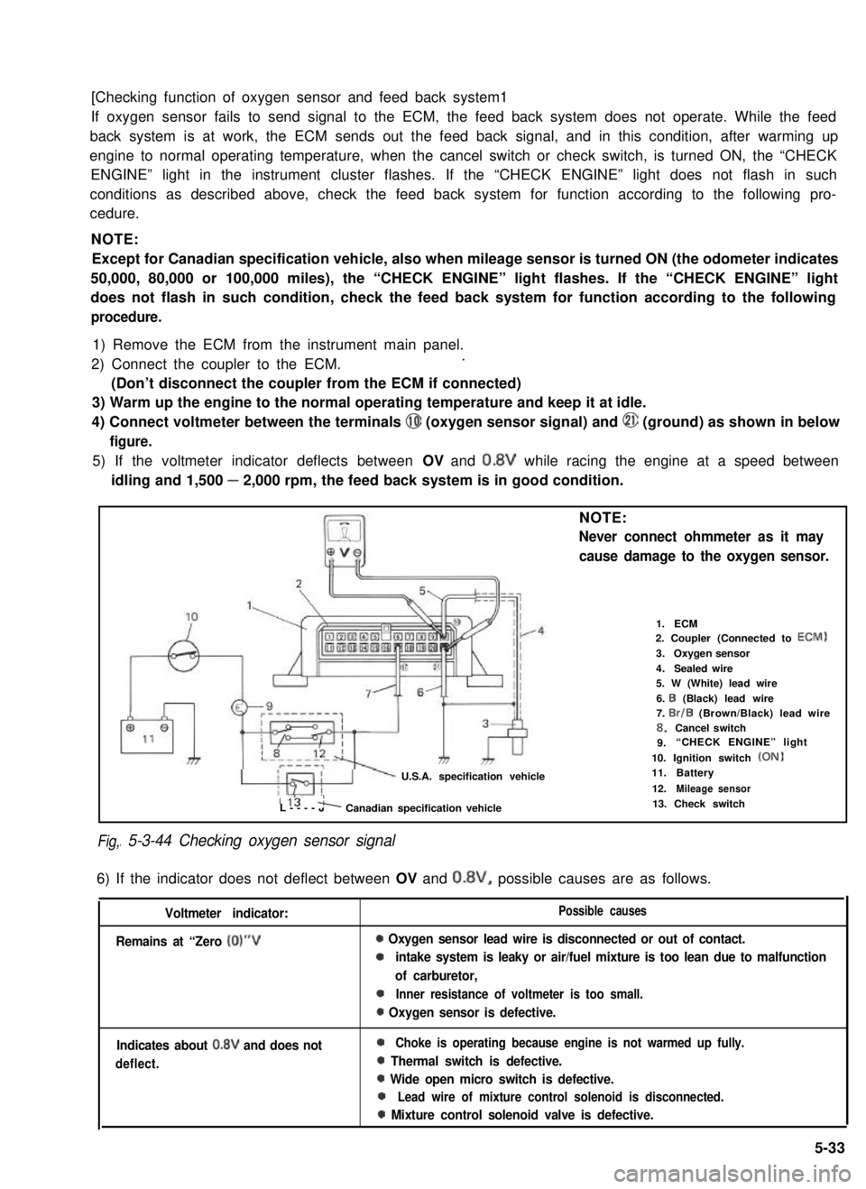
[Checking function of oxygen sensor and feed back system1
If oxygen sensor fails to send signal to the ECM, the feed back system does not operate. While the feed
back system is at work, the ECM sends out the feed back signal, and in this condition, after warming up
engine to normal operating temperature, when the cancel switch or check switch, is turned ON, the “CHECK
ENGINE” light in the instrument cluster flashes. If the “CHECK ENGINE” light does not flash in such
conditions as described above, check the feed back system for function according to the following pro-
cedure.
NOTE:
Except for Canadian specification vehicle, also when mileage sensor is turned ON (the odometer indicates
50,000, 80,000 or 100,000 miles), the “CHECK ENGINE” light flashes. If the “CHECK ENGINE” light
does not flash in such condition, check the feed back system for function according to the following
procedure.
1) Remove the ECM from the instrument main panel.
2) Connect the coupler to the ECM..
(Don’t disconnect the coupler from the ECM if connected)
3) Warm up the engine to the normal operating temperature and keep it at idle.
4) Connect voltmeter between the terminals @I (oxygen sensor signal) and @ (ground) as shown in below
figure.
5) If the voltmeter indicator deflects between OV and 0.8V while racing the engine at a speed between
idling and 1,500 - 2,000 rpm, the feed back system is in good condition.
Fig,
NOTE:
Never connect ohmmeter as it may
cause damage to the oxygen sensor.
U.S.A. specification vehicle
1.ECM2. Coupler (Connected to ECM)
3.Oxygen sensor
4.Sealed wire5. W (White) lead wire
6. I3 (Black) lead wire7. Br/B (Brown/Black) lead wire8.Cancel switch9.“CHECK ENGINE” light
10. Ignition switch (ON)11.Battery
12.Mileage sensor115 'L----JA Canadian specification vehicle
I 5-3-44 Checking oxygen sensor signal
13. Check switch
6) If the indicator does not deflect between OV and 0.8V, possible causes are as follows.
Voltmeter indicator:
Remains at “Zero (0)“V
Possible causes
0 Oxygen sensor lead wire is disconnected or out of contact.
0intake system is leaky or air/fuel mixture is too lean due to malfunction
of carburetor,
0Inner resistance of voltmeter is too small.
0 Oxygen sensor is defective.
Indicates about 0.8V and does not
deflect.
0Choke is operating because engine is not warmed up fully.
0 Thermal switch is defective.
0 Wide open micro switch is defective.
0Lead wire of mixture control solenoid is disconnected.
0 Mixture control solenoid valve is defective.
5-33