Page 411 of 962
4) Before installing brake drum, to maximize
brake shoe-todrum clearance, put screw
driver between rod and ratchet and push
down ratchet as shown in figure.
\
2. Ratchet
3. Driver
Below figure shows ratchet positionwhere brake shoe-to-drum clearanceis maximum.
Fig. 19-54
5) Install brake drum after making sure that
inside of brake drum and brake shoes are free
from dirt and oil.
6) Torque wheel nuts and brake drum nuts to
specification.
NOTE:
If brake backing plate was removed from wheel
cylinder or brake pipe was disconnected from
wheel cylinder. Bleed air from brake system.
(For bleeding operation, refer to p. 19-46.)
7) Upon completion of all jobs, depress brake
pedal with about 30 kg (66 Ibs) load four or
five times so as to obtain proper drum-to-
shoe clearance.
8) Check to ensure that brake drum is free from
dragging and proper braking is obtained. Then
remove car from hoist and perform brake test
(foot brake and parking brake).
Fig. 19-55
19-26
Page 422 of 962

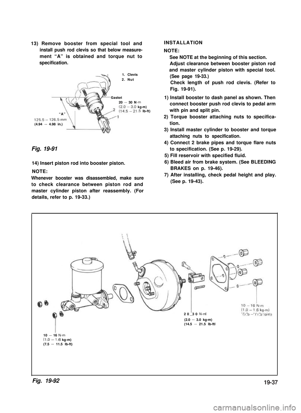
13) Remove booster from special tool and
install push rod clevis so that below measure-
ment “A” is obtained and torque nut to
specification.
-41. Clevis
2. Nut
Gasket20 - 30 N
“A”
125.5- 126.5mm(4.94 - 4.98 in.)\
.rnkg-m).5 lb-ft)
Fig. 19-91
14) Insert piston rod into booster piston.
NOTE:
Whenever booster was disassembled, make sure
to check clearance between piston rod and
INSTALLATION
NOTE:
See NOTE at the beginning of this section.
Adjust clearance between booster piston rod
and master cylinder piston with special tool.
(See page 19-33.)
Check length of push rod clevis. (Refer to
Fig. 19-91).
1) Install booster to dash panel as shown. Then
connect booster push rod clevis to pedal arm
with pin and split pin.
2) Torque booster attaching nuts to specifica-
tion.
3) Install master cylinder to booster and torque
attaching nuts to specification.
4) Connect 2 brake pipes and torque flare nuts
to specification. (See p. 19-29).
5) Fill reservoir with specified fluid.
6) Bleed air from brake system. (See BLEEDING
BRAKES on p. 19-46).
7) After installing, check pedal height and play.
(See p. 19-43).
master cylinder piston after reassembly. (For
details, refer to p. 19-33.)
20 30 N.m-(2.0 - 3.0 kg-m)(14.5 - 21.5 lb-ftl
10 - 16 N.m(1.0-1.6 kg-m)(7.5 - 11.5 lb-ft)
Fig. 19-9219-37
Page 428 of 962

BRAKE PEDAL FREE HEIGHT ADJUSTMENT
Brake pedal height is normal if brake pedal is
as high as clutch pedal.
1) When booster push rod clevis has been
reinstalled, it is important that measurement
between booster mounting surface (with a
gasket attached) and the center of clevis
pin hole is adjusted within 125.5 mm -
126.5 mm (4.94 - 4.98 in.). (See page
19-37.)
2) When stop light switch has been removed,
refer to the following STOP LIGHT SWITCH
ADJUSTMENT for proper installation.
The services in above steps 1) and 2) may
affect brake pedal height.
STOP LIGHT SWITCH ADJUSTMENT
Adjustment should be made as follows when
installing the switch.
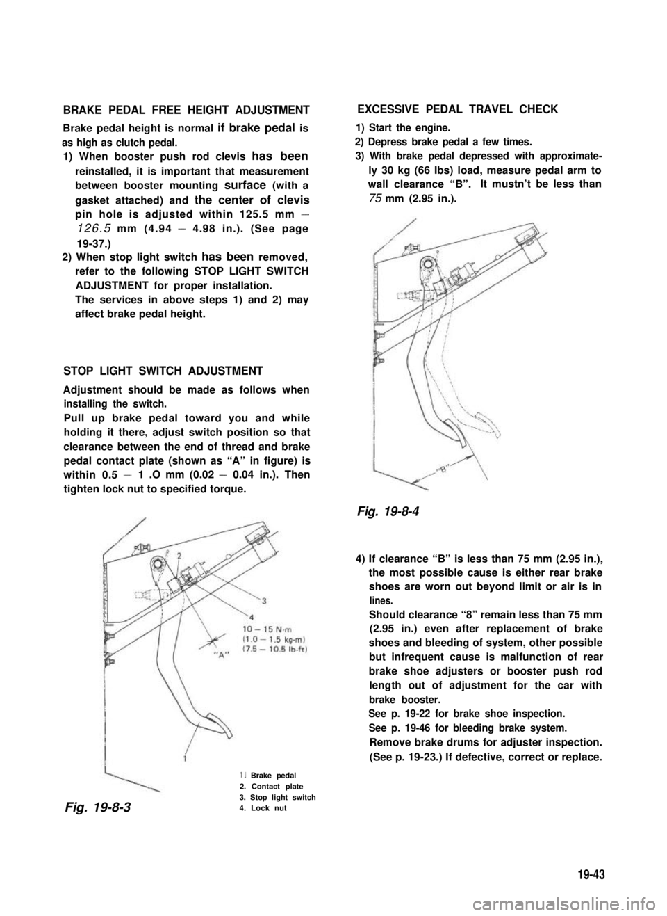
Pull up brake pedal toward you and while
holding it there, adjust switch position so that
clearance between the end of thread and brake
pedal contact plate (shown as “A” in figure) is
within 0.5 -1 .O mm (0.02 - 0.04 in.). Then
tighten lock nut to specified torque.
1. Brake pedal
2. Contact plate
3. Stop light switch4. Lock nut
EXCESSIVE PEDAL TRAVEL CHECK
1) Start the engine.
2) Depress brake pedal a few times.
3) With brake pedal depressed with approximate-
ly 30 kg (66 Ibs) load, measure pedal arm to
wall clearance “B”.It mustn’t be less than
75 mm (2.95 in.).
Fig. 19-8-4
4) If clearance “B” is less than 75 mm (2.95 in.),
the most possible cause is either rear brake
shoes are worn out beyond limit or air is in
lines.
Should clearance “8” remain less than 75 mm
(2.95 in.) even after replacement of brake
shoes and bleeding of system, other possible
but infrequent cause is malfunction of rear
brake shoe adjusters or booster push rod
length out of adjustment for the car with
brake booster.
See p. 19-22 for brake shoe inspection.
See p. 19-46 for bleeding brake system.
Remove brake drums for adjuster inspection.
(See p. 19-23.) If defective, correct or replace.
Fig. 19-8-3
19-43
Page 431 of 962

BLEEDING BRAKES
NOTE:
Brake fluid is extremely damaging to paint. If
fluid should accidentally touch painted surface,
immediately wipe fluid from paint and clean
painted surface.
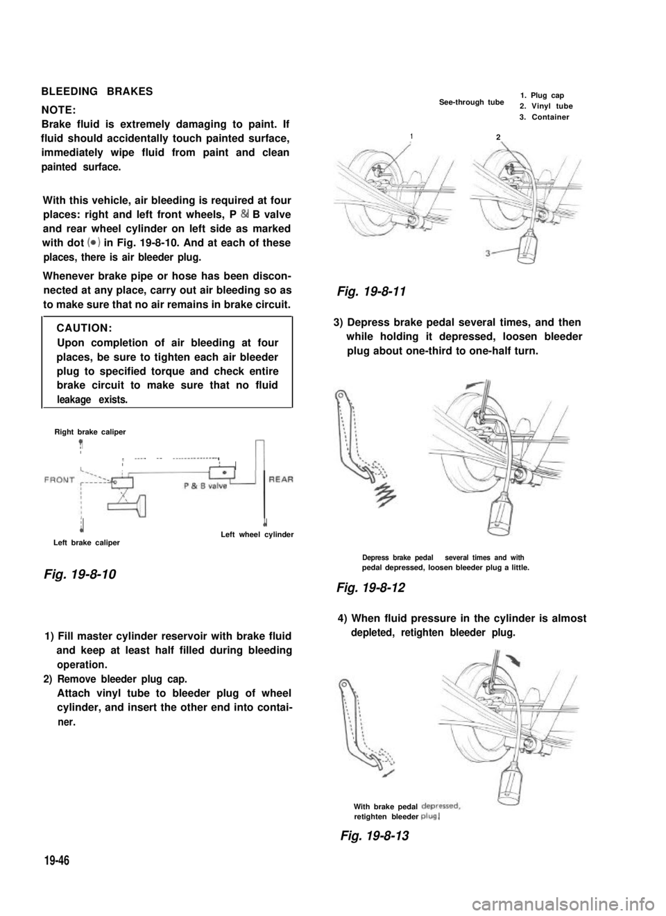
With this vehicle, air bleeding is required at four
places: right and left front wheels, P & B valve
and rear wheel cylinder on left side as marked
with dot (0) in Fig. 19-8-10. And at each of these
places, there is air bleeder plug.
Whenever brake pipe or hose has been discon-
nected at any place, carry out air bleeding so as
to make sure that no air remains in brake circuit.
CAUTION:
Upon completion of air bleeding at four
places, be sure to tighten each air bleeder
plug to specified torque and check entire
brake circuit to make sure that no fluid
leakage exists.
Right brake caliper
?Ir ____ -- ---------------,IIAn
i
Left brake caliper
1Left wheel cylinder
Fig. 19-8-10
1) Fill master cylinder reservoir with brake fluid
and keep at least half filled during bleeding
operation.
2) Remove bleeder plug cap.
Attach vinyl tube to bleeder plug of wheel
cylinder, and insert the other end into contai-
ner.
See-through tube1. Plug cap2. Vinyl tube
2
3. Container
1
Fig. 19-8-11
3) Depress brake pedal several times, and then
while holding it depressed, loosen bleeder
plug about one-third to one-half turn.
Depress brake pedal several times and withpedal depressed, loosen bleeder plug a little.
Fig. 19-8-12
4) When fluid pressure in the cylinder is almost
depleted, retighten bleeder plug.
With brake pedalretighten bleederplug.
Fig. 19-8-13
19-46
Page 432 of 962

5) Repeat this operation until there are no more
air bubbles in hydraulic line.
6) When bubbles stop, depress and hold brake
pedal and tighten bleeder plug.
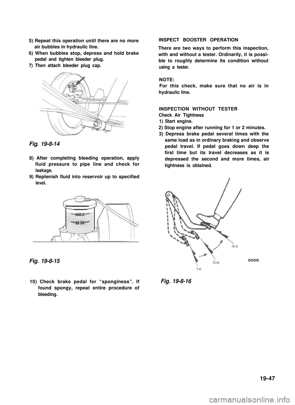
7) Then attach bleeder plug cap.
Fig. 19-8-14
8) After completing bleeding operation, apply
fluid pressure to pipe line and check for
leakage.
9) Replenish fluid into reservoir up to specified
level.
Fig. 19-8-15
INSPECT BOOSTER OPERATION
There are two ways to perform this inspection,
with and without a tester. Ordinarily, it is possi-
ble to roughly determine its condition without
using a tester.
NOTE:
For this check, make sure that no air is in
hydraulic line.
INSPECTION WITHOUT TESTER
Check Air Tightness
1) Start engine.
2) Stop engine after running for 1 or 2 minutes.
3) Depress brake pedal several times with the
same load as in ordinary braking and observe
pedal travel. If pedal goes down deep the
first time but its travel decreases as it is
depressed the second and more times, air
tightness is obtained.
GOOD
10) Check brake pedal for “sponginess”. If
’ found spongy, repeat entire procedure of
bleeding.
Fig. 19-8-16
19-47