1987 SUZUKI GRAND VITARA coolant temperature
[x] Cancel search: coolant temperaturePage 23 of 962
NOTE:
Steps 1) - 6) outlined above must be performed
with ENGINE NOT RUNNING. For step 7),
be sure to have adequate ventilation while
engine is running
It is recommended to use engine oil of SE or
SF class.
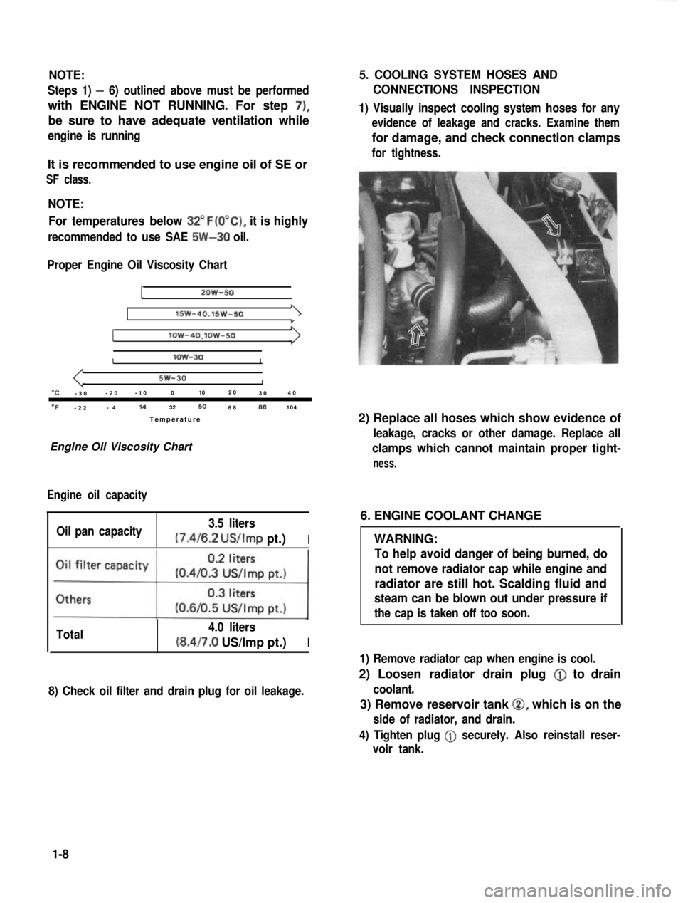
NOTE:For temperatures below
32”F(O”C), it is highly
recommended to use SAE 5W-30 oil.
Proper Engine Oil Viscosity Chart
12OW-50
lSW-40.15w-501
Ilow-4O.lOW-50
Ilow-30I
5w-30I“C-3 0 -2
0 -1
0 0 102
0
30 4
0
OF-2 2 -
4 14
32506886104
Temperatur e
Engine Oil Viscosity Chart
Engine oil capacity
Oil pan capacity 3.5 liters (7.4/6.2
US/Imp pt.)I
Total 4.0 liters(8.4/7.0 US/Imp pt.)I
8) Check oil filter and drain plug for oil leakage.
5. COOLING SYSTEM HOSES AND
CONNECTIONS INSPECTION
1) Visually inspect cooling system hoses for any
evidence of leakage and cracks. Examine them
for damage, and check connection clamps
for tightness.
2) Replace all hoses which show evidence of
leakage, cracks or other damage. Replace all
clamps which cannot maintain proper tight-
ness.
6. ENGINE COOLANT CHANGE
WARNING:
To help avoid danger of being burned, do
not remove radiator cap while engine and
radiator are still hot. Scalding fluid and
steam can be blown out under pressure if
the cap is taken off too soon.
1) Remove radiator cap when engine is cool.
2) Loosen radiator drain plug @
to drain
coolant.
3) Remove reservoir tank 0, which is on the
side of radiator, and drain.
4) Tighten plug
@ securely. Also reinstall reser-
voir tank.
1-8
Page 25 of 962
CAUTION:
When changing engine coolant, use mixture
of 56% water and 50% GOLDEN CRUISER
1200for the market where ambient tem-
perature falls lower than -16°C (3°F) in
winter and mixture of 70% water and
30% GOLDEN CRUISER 1200for the
market where ambient temperature doesn’t
fall lower than -16°C (3” F).
Even in a market where no freezing tempe-
rature is anticipated, mixture of 70% water
and 30% GOLDEN CRUISER 1200
should be used for the purpose of corro-
sion protection and lubrication.
7. EXHAUST PIPES AND MOUNTINGS
INSPECTION
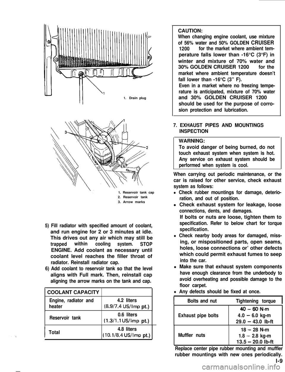
1.Drain plug
1. Reservoir tank cap2. Reservoir tank
3. Arrow marks
5) Fill radiator with specified amount of coolant,
and run engine for 2 or 3 minutes at idle.
This drives out any air which may still be
trappedwithincoolingsystem.STOP
ENGINE. Add coolant as necessary until
coolant level reaches the filler throat of
radiator. Reinstall radiator cap.
6) Add coolant to reservoir tank so that the level
aligns with Full mark. Then, reinstall cap
aligning the arrow marks on the tank and cap.
r.
COOLANT CAPACITY
Engine, radiator and4.2 liters
heater(8.9/7.4 US/Imp pt.)
Reservoir tank0.6 liters
(1.3/1.1 US/Imp pt.)
ITotal4.8 liters
(10.1/8.4US/lmp pt.)
WARNING:
To avoid danger of being burned, do not
touch exhaust system when system is hot.
Any service on exhaust system should be
performed when system is cool.
When carrying out periodic maintenance, or the
car is raised for other service, check exhaust
system as follows:
l Check rubber mountings for damage, deterio-
ration, and out of position.
l Check exhaust system for leakage, loose
connections, dents, and damages.
If bolts or nuts are loose, tighten them to
specification. Refer to below chart for torque
specification.
l Check nearby body areas for damaged, miss-
ing, or mispositioned parts, open seams,
holes, loose connections or’ other defects
which could permit exhaust fumes to seep
into the car.
l Make sure that exhaust system components
have enough clearance from the underbody to
avoid overheating and possible damage to the
floor carpet.
l Any defects should be fixed at once.
IBolts and nutTightening torqueI
40-80 N-m
Exhaustpipebolts4.0-6.0 kg-m
29.0-43.0 lb-ft
Muffler nuts
18 - 28 N-m
1.8 - 2.8 kg-m
13.5 - 20.0 lb-ft
Replace center pipe rubber mounting and muffler
rubber mountings with new ones periodically.
l-9
Page 125 of 962
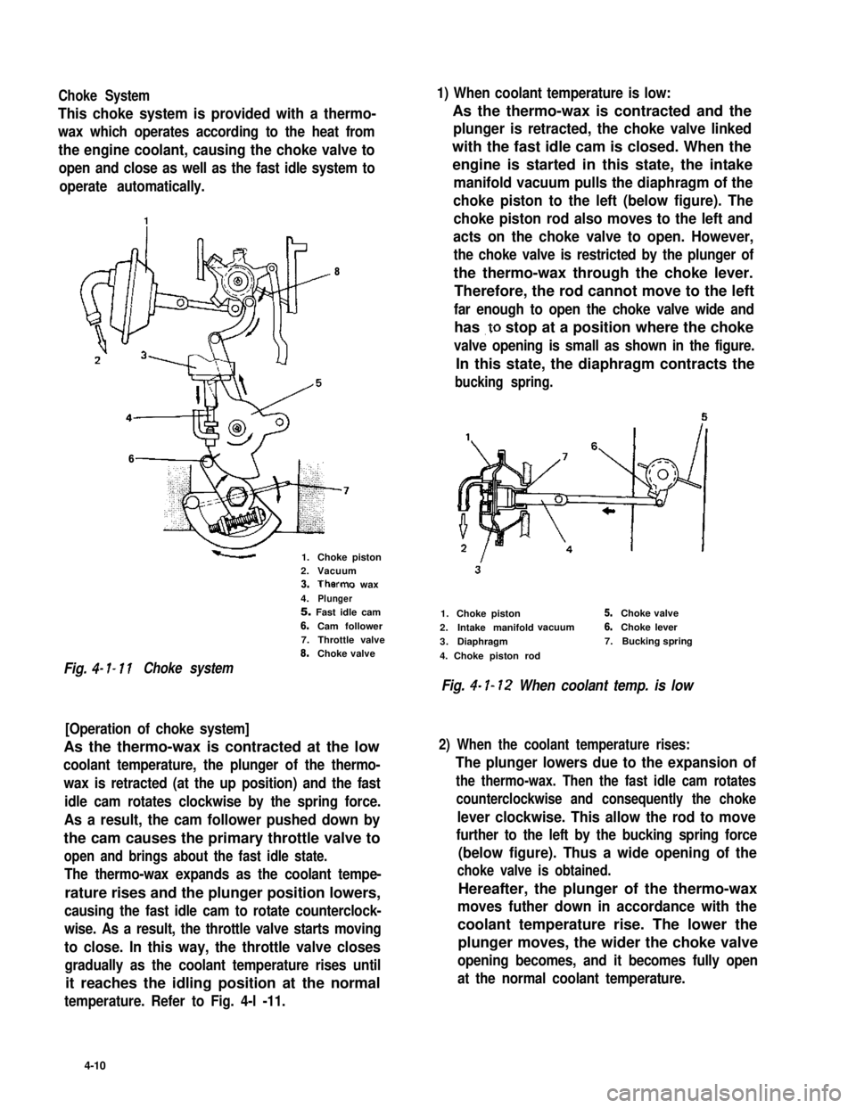
Choke System1) When coolant temperature is low:
This choke system is provided with a thermo-
wax which operates according to the heat from
the engine coolant, causing the choke valve to
open and close as well as the fast idle system to
operate automatically.
As the thermo-wax is contracted and the
plunger is retracted, the choke valve linked
with the fast idle cam is closed. When the
engine is started in this state, the intake
manifold vacuum pulls the diaphragm of the
choke piston to the left (below figure). The
choke piston rod also moves to the left and
acts on the choke valve to open. However,
the choke valve is restricted by the plunger of
the thermo-wax through the choke lever.
Therefore, the rod cannot move to the left
far enough to open the choke valve wide and
has .to stop at a position where the choke
valve opening is small as shown in the figure.
In this state, the diaphragm contracts the
bucking spring.
8
6
1.Choke piston2.Vacuum3.Therms wax
4.Plunger5. Fast idle cam
6.Cam follower7.Throttle valve8.Choke valve
Fig. 4- I- 11Choke system
[Operation of choke system]
As the thermo-wax is contracted at the low
coolant temperature, the plunger of the thermo-
wax is retracted (at the up position) and the fast
idle cam rotates clockwise by the spring force.
As a result, the cam follower pushed down by
the cam causes the primary throttle valve to
open and brings about the fast idle state.
The thermo-wax expands as the coolant tempe-
rature rises and the plunger position lowers,
causing the fast idle cam to rotate counterclock-
wise. As a result, the throttle valve starts moving
to close. In this way, the throttle valve closes
gradually as the coolant temperature rises until
it reaches the idling position at the normal
temperature. Refer to Fig. 4-l -11.
1.Choke piston
2.Intake manifoldvacuum
3.Diaphragm
4. Choke piston rod
5.Choke valve
6.Choke lever
7.Bucking spring
Fig. 4- I- 12 When coolant temp. is low
2) When the coolant temperature rises:
The plunger lowers due to the expansion of
the thermo-wax. Then the fast idle cam rotates
counterclockwise and consequently the choke
lever clockwise. This allow the rod to move
further to the left by the bucking spring force
(below figure). Thus a wide opening of the
choke valve is obtained.
Hereafter, the plunger of the thermo-wax
moves futher down in accordance with the
coolant temperature rise. The lower the
plunger moves, the wider the choke valve
opening becomes, and it becomes fully open
at the normal coolant temperature.
4-10
Page 126 of 962
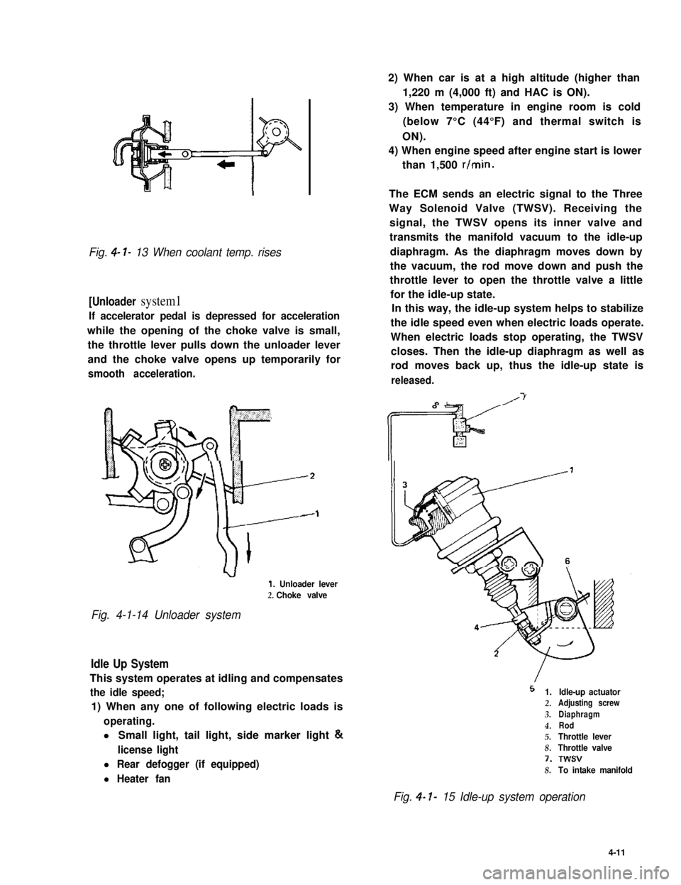
Fig. 4- l- 13 When coolant temp. rises
[Unloader system1
If accelerator pedal is depressed for acceleration
while the opening of the choke valve is small,
the throttle lever pulls down the unloader lever
and the choke valve opens up temporarily for
smooth acceleration.
1. Unloader lever
2. Choke valve
Fig. 4-1-14 Unloader system
Idle Up System
This system operates at idling and compensates
the idle speed;
1) When any one of following electric loads is
operating.
l Small light, tail light, side marker light &
license light
l Rear defogger (if equipped)
l Heater fan
2) When car is at a high altitude (higher than
1,220 m (4,000 ft) and HAC is ON).
3) When temperature in engine room is cold
(below 7°C (44°F) and thermal switch is
ON).
4) When engine speed after engine start is lower
than 1,500 r/min.
The ECM sends an electric signal to the Three
Way Solenoid Valve (TWSV). Receiving the
signal, the TWSV opens its inner valve and
transmits the manifold vacuum to the idle-up
diaphragm. As the diaphragm moves down by
the vacuum, the rod move down and push the
throttle lever to open the throttle valve a little
for the idle-up state.
In this way, the idle-up system helps to stabilize
the idle speed even when electric loads operate.
When electric loads stop operating, the TWSV
closes. Then the idle-up diaphragm as well as
rod moves back up, thus the idle-up state is
released.
I
5 1.
2.
3.
4.5.
8.
7.
8.
Idle-up actuatorAdjusting screw
Diaphragm
Rod
Throttle lever
Throttle valve
Twsv
To intake manifold
Fig. 4- I- 15 Idle-up system operation
4-11
Page 137 of 962
![SUZUKI GRAND VITARA 1987 Service Repair Manual Ambient temperatureClearance
Fig. 4-l-47
Choke Adjustment
Perform following check and adjustments with
air intake case removed when engine is cold.
[Choke valve]
1) Check choke valve for smooth moveme SUZUKI GRAND VITARA 1987 Service Repair Manual Ambient temperatureClearance
Fig. 4-l-47
Choke Adjustment
Perform following check and adjustments with
air intake case removed when engine is cold.
[Choke valve]
1) Check choke valve for smooth moveme](/manual-img/20/57437/w960_57437-136.png)
Ambient temperatureClearance
Fig. 4-l-47
Choke Adjustment
Perform following check and adjustments with
air intake case removed when engine is cold.
[Choke valve]
1) Check choke valve for smooth movement by
pushing it with a finger.
Fig. 4-l-48 Choke valve
2) Make sure that choke valve is closed almost
completely when ambient temperature is
below 25°C (77” F) and engine is cold.
3) Check to ensure that choke valve to carbure-
tor bore clearance is within following specifi-
cations when engine is cool.
I.6 mmC&n*?.:.. \
NOTE:
As ambient temperature or engine coolant
temperature rises high, clearance increases.
1. Choke valve2. Thickness gauge
Fig. 4- 149 Choke valve to carbure tar bore
clearance
4) If clearance is found excessively large or
small in the above check, check strangler
spring, choke piston and each link in choke
system for smooth operation. Lubricate
choke valve shaft and each link with spray
lubricant if necessary.
Fig. 4-l-50
4-22
Page 161 of 962
![SUZUKI GRAND VITARA 1987 Service Repair Manual COMPUTER CONTROLLED EMISSION CONTROL SYSTEM
[Feed back system]
A prime purpose of this system is to maintain a controlled air fuel ratio, allowing the catalyst to reduce
oxides of nitrogen, hydrocarbo SUZUKI GRAND VITARA 1987 Service Repair Manual COMPUTER CONTROLLED EMISSION CONTROL SYSTEM
[Feed back system]
A prime purpose of this system is to maintain a controlled air fuel ratio, allowing the catalyst to reduce
oxides of nitrogen, hydrocarbo](/manual-img/20/57437/w960_57437-160.png)
COMPUTER CONTROLLED EMISSION CONTROL SYSTEM
[Feed back system]
A prime purpose of this system is to maintain a controlled air fuel ratio, allowing the catalyst to reduce
oxides of nitrogen, hydrocarbons, carbon monoxide and to improve fuel economy simultaneously.
The electronic control module (ECM) and the oxygen sensor are provided in this system.
The oxygen sensor mounted on the exhaust manifold monitors the exhaust gas air fuel ratio and signals to
the ECM.
The ECM processes the oxygen sensor signal and controls carburetor air fuel ratio by the operation of the
mixture control solenoid in the carburetor.
Thus the signal of the exhaust gas air fuel ratio sensed by the oxygen sensor is fed back to ECM and the
carburetor air fuel ratio is controlled.
[Electronic control module (ECM)]
The ECM controls the fuel cut system, idle-up system, bowl vent system, EGR system and secondary
throttle valve system, as well as the feed back system. The ECM is located under the glove box of the
instrument main panel. Refer to Fig. 5-l -9.
I1
* Engine coolant
temperature
* Engine speed
-Electronic
controlmodule
I I
* Throttle positiont(Micro Switches)
I I I\-
* Fuel cut solenoid valve
-44
* Engine room
- * Vent solenoid valvetempe.rature
* Idle-up actuator (TWSV)* Electric load
* Secondary throttle valve (VSV) , _ ~
r* Mixture control
solenoid valve
* Barometric
pressure
+ ECM supply
voltage
* Gear position
Fig. 5-l-8Computer con trolled emissioncon trot s ys tern
5- 10
Page 162 of 962
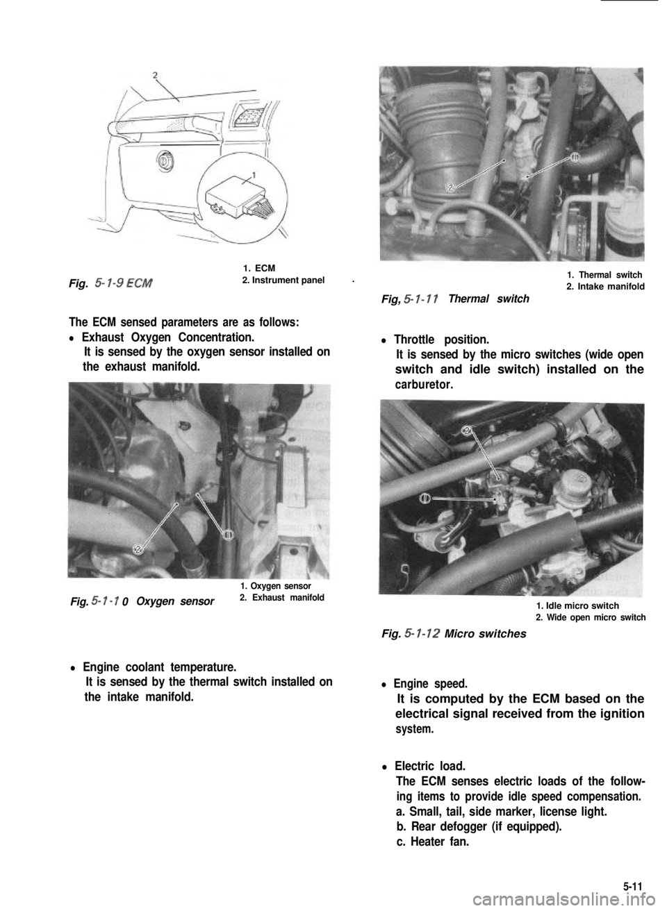
Fig. 5- l-9 ECM
1. ECM
2. Instrument panel.
The ECM sensed parameters are as follows:
l Exhaust Oxygen Concentration.
It is sensed by the oxygen sensor installed on
the exhaust manifold.
1. Oxygen sensor
Fig. 5- I - 7 0Oxygen sensor2. Exhaust manifold
l Engine coolant temperature.
It is sensed by the thermal switch installed on
the intake manifold.
1. Thermal switch
2. Intake manifold
Fig, 5- I- 17Thermal switch
l Throttle position.
It is sensed by the micro switches (wide open
switch and idle switch) installed on the
carburetor.
1. Idle micro switch
2. Wide open micro switch
Fig. 5- 1-12 Micro switches
l Engine speed.
It is computed by the ECM based on the
electrical signal received from the ignition
system.
l Electric load.
The ECM senses electric loads of the follow-
ing items to provide idle speed compensation.
a. Small, tail, side marker, license light.
b. Rear defogger (if equipped).
c. Heater fan.
5-11
Page 164 of 962
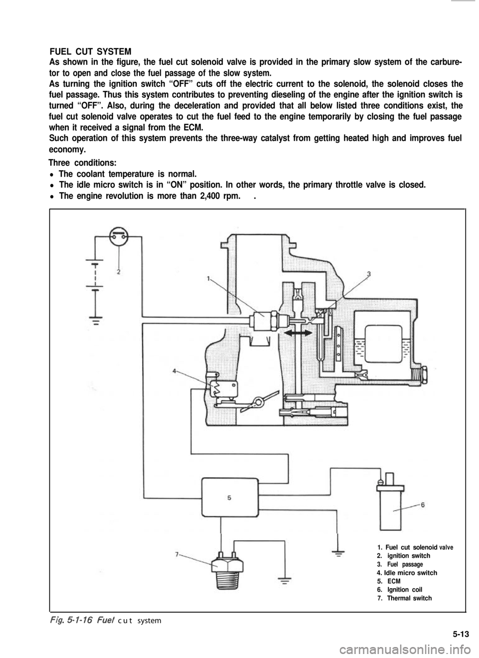
FUEL CUT SYSTEM
As shown in the figure, the fuel cut solenoid valve is provided in the primary slow system of the carbure-
tor to open and close the fuel passage of the slow system.
As turning the ignition switch “OFF” cuts off the electric current to the solenoid, the solenoid closes the
fuel passage. Thus this system contributes to preventing dieseling of the engine after the ignition switch is
turned “OFF”. Also, during the deceleration and provided that all below listed three conditions exist, the
fuel cut solenoid valve operates to cut the fuel feed to the engine temporarily by closing the fuel passage
when it received a signal from the ECM.
Such operation of this system prevents the three-way catalyst from getting heated high and improves fuel
economy.
Three conditions:
l The coolant temperature is normal.
l The idle micro switch is in “ON” position. In other words, the primary throttle valve is closed.
l The engine revolution is more than 2,400 rpm..
1. Fuel cut solenoid
2.ignition switch
3.Fuel passage
4. Idle micro switch
5.ECM
6.Ignition coil
7.Thermal switch
valve
-. .t/g. cut system
5-13