Page 4 of 962

O-2. STANDARD SHOP PRACTICES
1. Protect painted surfaces of the body, and
avoid staining or tearing seats. When working
on fenders and seats, be sure to cover them
up with sheets.
2. Disconnect negative terminal connection of
the battery when working on any electrical
part or component. This is necessary for
avoiding electrical shocks and short-circuit-
ing, and is very simple to accomplish: merely
loosen wing nut on negative terminal and
separate cable from terminal post.
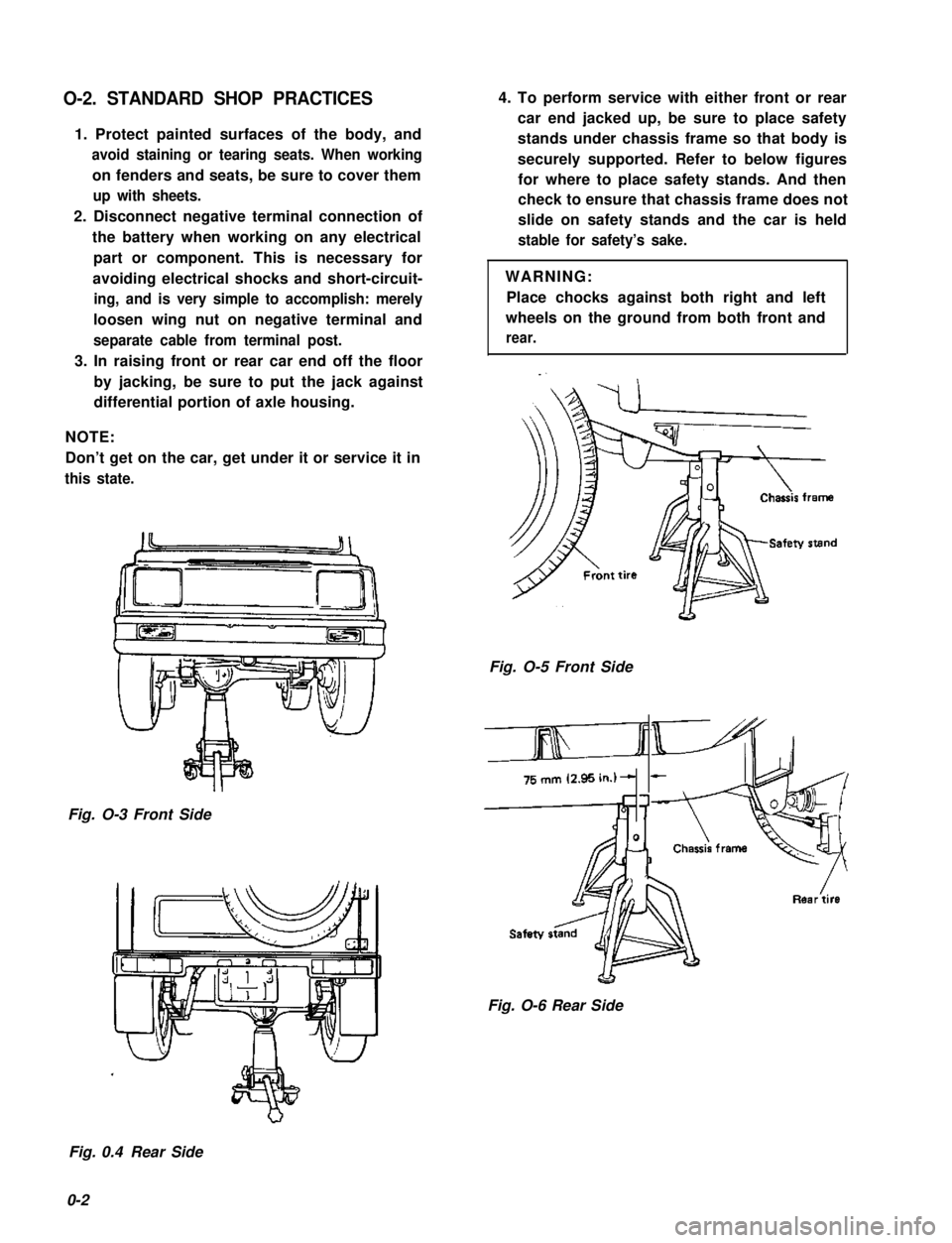
3. In raising front or rear car end off the floor
by jacking, be sure to put the jack against
differential portion of axle housing.
NOTE:
Don’t get on the car, get under it or service it in
this state.
Fig. O-3 Front Side
4. To perform service with either front or rear
car end jacked up, be sure to place safety
stands under chassis frame so that body is
securely supported. Refer to below figures
for where to place safety stands. And then
check to ensure that chassis frame does not
slide on safety stands and the car is held
stable for safety’s sake.
WARNING:
Place chocks against both right and left
wheels on the ground from both front and
rear.
Fig. O-5 Front Side
&
Fig. O-6 Rear Side
Fig. 0.4 Rear Side
0-2
Page 321 of 962

16-2. REMOVAL
1. Loosen, but do not remove, wheel nuts of
front or rear wheels, and raise car off the
2.
3.
floor by jacking.
Rest car steady on safety stands.
Drain out oil in differential housing by
loosening drain plug.
Remove wheel nuts and take off wheels,
front or rear. Each wheel has five wheel nuts.
For Front Differential
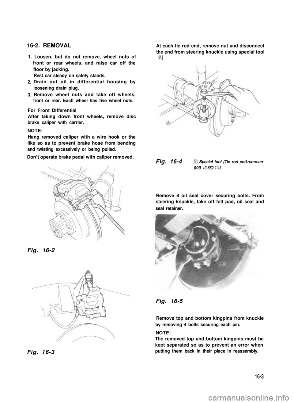
After taking down front wheels, remove disc
brake caliper with carrier.
NOTE:
Hang removed caliper with a wire hook or the
like so as to prevent brake hose from bending
and twisting excessively or being pulled.
Don’t operate brake pedal with caliper removed.
Fig. 16-2
Fig. 16-3
At each tie rod end, remove nut and disconnect
the end from steering knuckle using special tool
@
Fig. 16-4@ Special tool (Tie rod end remover
099 13-652 10)
Remove 8 oil seal cover securing bolts. From
steering knuckle, take off felt pad, oil seal and
seal retainer.
Fig. 16-5
Remove top and bottom kingpins from knuckle
by removing 4 bolts securing each pin.
NOTE:
The removed top and bottom kingpins must be
kept separated so as to prevent an error when
putting them back in their place in reassembly.
16-3
Page 340 of 962
Front Wheel Hub 81 Bearing
1. Loosen the five nuts securing the wheel.
Raise the front end by jacking.
Rest the machine steady on safety stands.
2. Remove the five nuts and take off the wheel.
Fig. 17-1-8
3. Remove the caliper with carrier by loosen-
ing carrier bolts.
NOTE:
Hang removed caliper with a wire hook or the
like so as to prevent brake hose from bending
and twisting excessively or being pulled.
Don’t operate brake pedal with caliper removed.
Fig. 17-1-9
4. Remove brake disc.
NOTE:
If brake disc can not be removed by hand, use
8 mm bolts as shown below.
f
@
[For car equipped with free wheeling hub]
5. Remove free wheeling hub cover and circlip.
Fig. 17-1-12-1 @ Circlip remover (09900-06107)
6. Remove free wheeling hub body.
Fig. 17-1-10
17-6Fig. 17-1-12-2
8mm BoltFig. 17-1-11