1987 SUZUKI GRAND VITARA brake pads
[x] Cancel search: brake padsPage 20 of 962
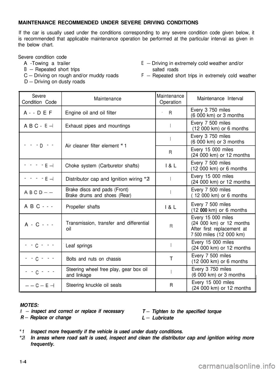
MAINTENANCE RECOMMENDED UNDER SEVERE DRIVING CONDITIONS
If the car is usually used under the conditions corresponding to any severe condition code given below, it
is recommended that applicable maintenance operation be performed at the particular interval as given in
the below chart.
Severe condition code
A -Towing a trailer
B- Repeated short trips
C - Driving on rough and/or muddy roads
D - Driving on dusty roads
E- Driving in extremely cold weather and/or
salted roads
F- Repeated short trips in extremely cold weather
Severe
Condition CodeMaintenanceMaintenance
OperationMaintenance Interval
A--DEFEngine oil and oil filter_ REvery 3 750 miles
(6 000 km) or 3 months
ABC- E-Exhaust pipes and mountingsIEvery 7 500 miles
(12 000 km) or 6 months
IEvery 3 750 miles
D(6 000 km) or 3 months--- --Air cleaner filter element * 1
REvery 15 000 miles
(24 000 km) or 12 months
----E-Choke system (Carburetor shafts)I&LEvery 7 500 miles
(12 000 km) or 6 months
----E-Distributor cap and Ignition wiring “2IEvery 15 000 miles
(24 000 km) or 12 months
ABCD--Brake discs and pads (Front)IEvery 7 500 miles
Brake drums and shoes (Rear)( 12 000 km) or 6 months
ABC---Propeller shaftsI&LEvery 7 500 miles
(12 000 km) or 6 months
Every 15 000 miles
A-C---Transmission, transfer and differential(24 000 km) or 12 months
oilRAfter first replacement at
7 500 miles (12 000 km)
CEvery 15 000 miles-- ---’ Leaf springsI(24 000 km) or 12 months
C-- ---Bolts and nuts on chassisTEvery 7 500 miles
(12 000 km) or 6 months
CSteering wheel free play, gear box oil-- ---and linkageIEvery 3 750 miles
(6 000 km) or 3 months
--C-E-Steering knuckle oil sealsREvery 15 000 miles
(24 000 km) or 12 months
MOTES:
I- inspect and correct or replace if necessary
R - Replace or change
T - Tighten to the specified torque
L - Lubricate
* 1Inspect more frequently if the vehicle is used under dusty conditions.
*2In areas where road salt is used, inspect and clean the distributor cap and ignition wiring more
frequently.
1-4
Page 33 of 962
1-3. CHASSIS AND BODY
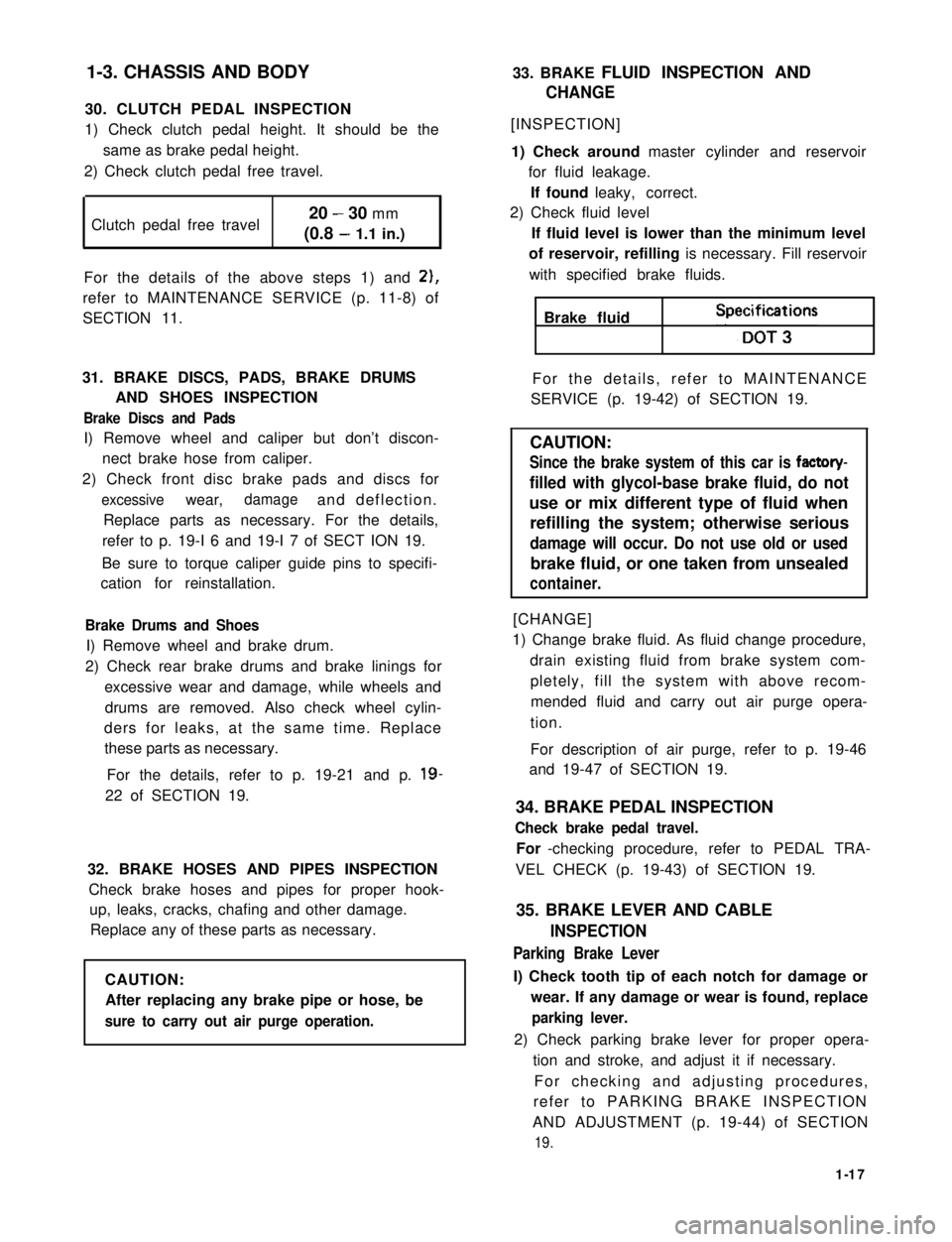
30. CLUTCH PEDAL INSPECTION
1) Check clutch pedal height. It should be the
same as brake pedal height.
2) Check clutch pedal free travel.
Clutch pedal free travel20 - 30 mm
(0.8 - 1.1 in.)
For the details of the above steps 1) and 2),
refer to MAINTENANCE SERVICE (p. 11-8) of
SECTION 11.
31. BRAKE DISCS, PADS, BRAKE DRUMS
AND SHOES INSPECTION
Brake Discs and Pads
I) Remove wheel and caliper but don’t discon-
nect brake hose from caliper.
2) Check front disc brake pads and discs for
excessivewear,damageand deflection.
Replace parts as necessary. For the details,
refer to p. 19-I 6 and 19-I 7 of SECT ION 19.
Be sure to torque caliper guide pins to specifi-
cation for reinstallation.
Brake Drums and Shoes
I) Remove wheel and brake drum.
2) Check rear brake drums and brake linings for
excessive wear and damage, while wheels and
drums are removed. Also check wheel cylin-
ders for leaks, at the same time. Replace
these parts as necessary.
For the details, refer to p. 19-21 and p. 19-
22 of SECTION 19.
32. BRAKE HOSES AND PIPES INSPECTION
Check brake hoses and pipes for proper hook-
up, leaks, cracks, chafing and other damage.
Replace any of these parts as necessary.
CAUTION:
After replacing any brake pipe or hose, be
sure to carry out air purge operation.
33. BRAKE FLUID INSPECTION AND
CHANGE
[INSPECTION]
1) Check around master cylinder and reservoir
for fluid leakage.
If found leaky, correct.
2) Check fluid level
If fluid level is lower than the minimum level
of reservoir, refilling is necessary. Fill reservoir
with specified brake fluids.
Brake fluid Speifi;t3ons
For the details, refer to MAINTENANCE
SERVICE (p. 19-42) of SECTION 19.
CAUTION:
Since the brake system of this car is factory-
filled with glycol-base brake fluid, do not
use or mix different type of fluid when
refilling the system; otherwise serious
damage will occur. Do not use old or used
brake fluid, or one taken from unsealed
container.
[CHANGE]
1) Change brake fluid. As fluid change procedure,
drain existing fluid from brake system com-
pletely, fill the system with above recom-
mended fluid and carry out air purge opera-
tion.
For description of air purge, refer to p. 19-46
and 19-47 of SECTION 19.
34. BRAKE PEDAL INSPECTION
Check brake pedal travel.
For -checking procedure, refer to PEDAL TRA-
VEL CHECK (p. 19-43) of SECTION 19.
35. BRAKE LEVER AND CABLE
INSPECTION
Parking Brake Lever
I) Check tooth tip of each notch for damage or
wear. If any damage or wear is found, replace
parking lever.
2) Check parking brake lever for proper opera-
tion and stroke, and adjust it if necessary.
For checking and adjusting procedures,
refer to PARKING BRAKE INSPECTION
AND ADJUSTMENT (p. 19-44) of SECTION
19.
1-17
Page 50 of 962
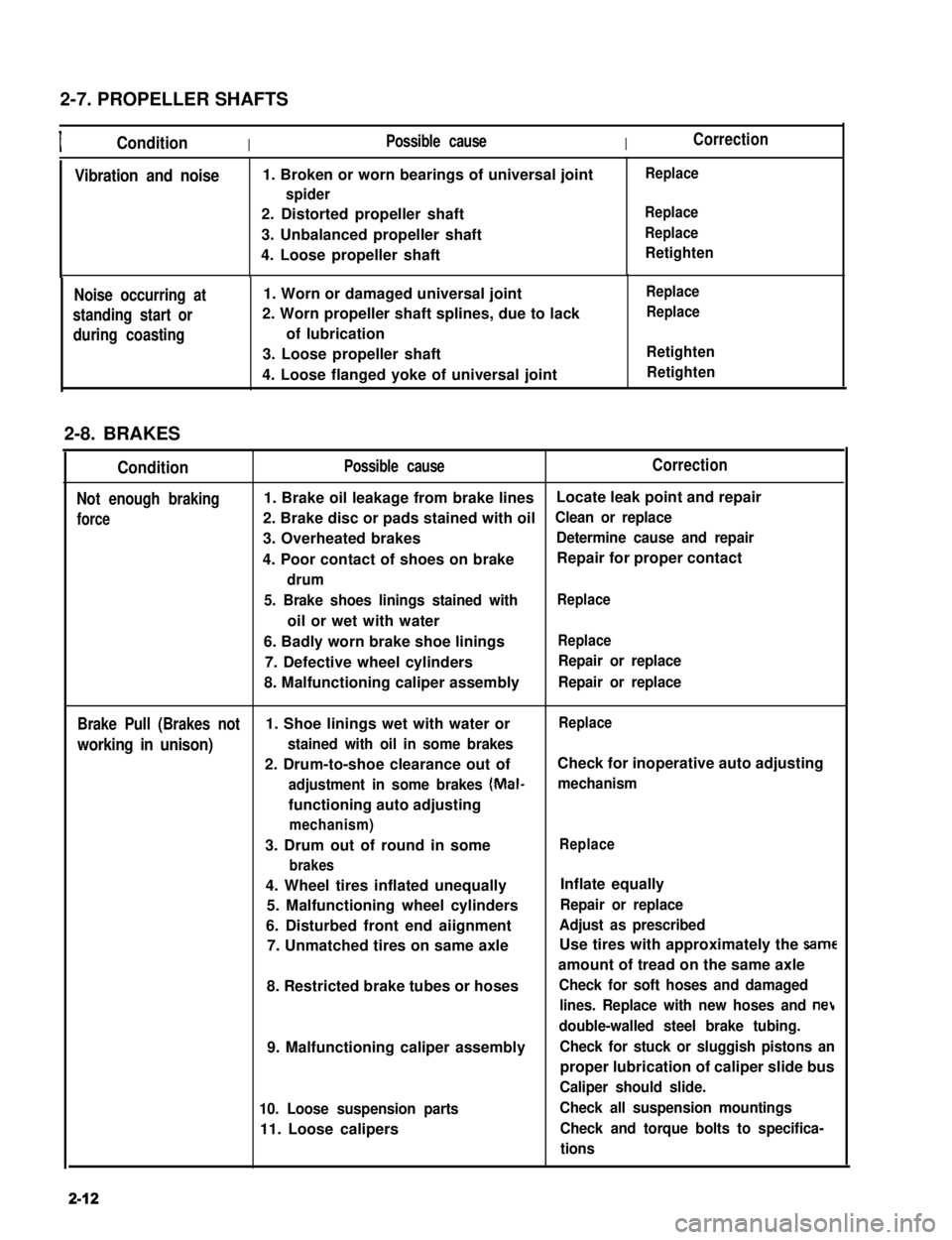
2-7. PROPELLER SHAFTS
IConditionIPossible causeICorrection
Vibration and noise1. Broken or worn bearings of universal joint
spider
2. Distorted propeller shaft
3. Unbalanced propeller shaft
4. Loose propeller shaft
Replace
Replace
Replace
Retighten
Noise occurring at
standing start or
during coasting
1. Worn or damaged universal joint
2. Worn propeller shaft splines, due to lack
of lubrication
3. Loose propeller shaft
4. Loose flanged yoke of universal joint
Replace
Replace
Retighten
Retighten
2-8. BRAKES
Condition
Not enough braking
force
Possible causeCorrection
1. Brake oil leakage from brake linesLocate leak point and repair
2. Brake disc or pads stained with oilClean or replace
3. Overheated brakesDetermine cause and repair
4. Poor contact of shoes on brakeRepair for proper contact
drum
5. Brake shoes linings stained with
oil or wet with water
Replace
6. Badly worn brake shoe liningsReplace
7. Defective wheel cylindersRepair or replace
8. Malfunctioning caliper assemblyRepair or replace
Brake Pull (Brakes not1. Shoe linings wet with water orReplace
working in unison)stained with oil in some brakes
2. Drum-to-shoe clearance out ofCheck for inoperative auto adjusting
adjustment in some brakes (Mal-mechanism
functioning auto adjusting
mechanism)
3. Drum out of round in some
brakes
Replace
4. Wheel tires inflated unequally
5. Malfunctioning wheel cylinders
6. Disturbed front end aiignment
7. Unmatched tires on same axle
8. Restricted brake tubes or hoses
9. Malfunctioning caliper assembly
10. Loose suspension parts
11. Loose calipers
Inflate equally
Repair or replace
Adjust as prescribed
Use tires with approximately the same
amount of tread on the same axle
Check for soft hoses and damaged
lines. Replace with new hoses and net
double-walled steel brake tubing.
Check for stuck or sluggish pistons an
proper lubrication of caliper slide bus
Caliper should slide.
Check all suspension mountings
Check and torque bolts to specifica-
tions
2-12
Page 391 of 962
![SUZUKI GRAND VITARA 1987 Service Repair Manual DISC BRAKE CALIPER ASSEMBLY
[GENERAL DESCRIPTION]
This caliper has a single 51.1 mm (2.012 in.) bore and is mounted to the brake caliper holder with two
mounting bolts. Hydraulic force, created by app SUZUKI GRAND VITARA 1987 Service Repair Manual DISC BRAKE CALIPER ASSEMBLY
[GENERAL DESCRIPTION]
This caliper has a single 51.1 mm (2.012 in.) bore and is mounted to the brake caliper holder with two
mounting bolts. Hydraulic force, created by app](/manual-img/20/57437/w960_57437-390.png)
DISC BRAKE CALIPER ASSEMBLY
[GENERAL DESCRIPTION]
This caliper has a single 51.1 mm (2.012 in.) bore and is mounted to the brake caliper holder with two
mounting bolts. Hydraulic force, created by applying force to the brake pedal, is converted by the caliper
to friction. The hydraulic force acts equally against the piston and the bottom of the caliper bore to move
the piston outward and to move (slide) the caliper inward, resulting in a clamping action on the disc. This
clamping action forces the pads (linings) against the disc, creating friction to stop the car.
For details, refer to OPERATION in the next page.
NOTE:
Lubricate parts as specified. Do not use lubricated shop air on brake parts as damage to rubber compo-
nents may result If any component is removed or line disconnected, bleed the brake system. Replace
pads in axle sets only. The torque values specified are for dry, unlubricated fasteners.
1. Caliper guide pin
2. Caliper guide pin sleeve
3. Guide pin boot
4. Guide pin cap
5. Bleeder plug cap
6.Bleeder plug
7. Disc brake caliper(Disc brake cylinder)
8.Piston seal9. Disc brake piston
10.Cylinder boot
11. Disc brake pad12. Disc brake carrier
13. Caliper antirattle clip14.Caliper holder
15.Dust cover16.Brake disc
Fig. 19-5
19-6
Page 392 of 962
![SUZUKI GRAND VITARA 1987 Service Repair Manual [Caliper OPERATION]
Single piston floating caliper type
The single piston floating caliper type brake is
employed in this model. One cylinder and one
piston are used for this type. (The cylinder is
co SUZUKI GRAND VITARA 1987 Service Repair Manual [Caliper OPERATION]
Single piston floating caliper type
The single piston floating caliper type brake is
employed in this model. One cylinder and one
piston are used for this type. (The cylinder is
co](/manual-img/20/57437/w960_57437-391.png)
[Caliper OPERATION]
Single piston floating caliper type
The single piston floating caliper type brake is
employed in this model. One cylinder and one
piston are used for this type. (The cylinder is
constructed as a monoblock with the caliper.)
Fluid pressure generated in the cylinder causes
the pad (1) on the piston side to press against
the disc. At the same time, the floating type
caliper body is moved to the right by the cylin-
der pressure, as shown in below figure, which
pulls pad (2) against the disc and so brakes the
wheel.
Caliper body
\Brake disc (rotor)
Fig. 19-6 - ’
The disc brake has no servo assistance as in drum
braking, and it is necessary to increase the work-
ing pressure of the piston and pad. For this pur-
pose, the wheel cylinder has a large bore. Even
only a little change in clearance between the disc
and pad has therefore a large influence on the
brake pedal stroke. It is necessary to have the
clearance adjusted to the minimum at all times,
by means of the piston (rubber) seal.
Piston seal (Rubber seal)Piston sealWinder (Rubber seal)
II
IPiston
Hydraulic pressure
“OFF“
Fig. 19-7
Clearance correction
Piston
Hydraulic pressure
“ON”
When oil pressure is applied to the piston, the
piston moves forward. The rubber seal, which
exerts considerable pressure against the piston,
moves with the cylinder. However, as a part of
the rubber seal has been fixed into a groove in
the cylinder, the shape of the rubber seal is dis-
torted toward internal end of the cylinder, as
shown in above figure. When pressure is taken
off from the foot brake pedal and fluid pressure
is released from the piston, a restoring force is
generated at the seal and pushes the piston back.
As the pads wear away and the clearance be-
tween the disc and pads becomes larger, the
piston moves a larger distance. The seal then
could change in shape further but, since the end
of the seal is fixed into the groove in the cylin-
der, the distortion is limited to the same amount
as previously described. The piston moves
further to cover the distance of clearance. The
piston returns by the same distance and the
rubber seal recovers its shape as described
above and thus the clearance between the disc
and pads are maintained in adjustment.
19-7
Cylinder
Page 399 of 962
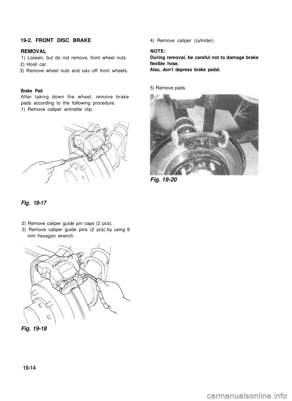
19-2. FRONT DISC BRAKE4) Remove caliper (cylinder).
REMOVAL
1) Loosen, but do not remove, front wheel nuts.
2) Hoist car.
3) Remove wheel nuts and take off front wheels.
Brake Pad
After taking down the wheel, remove brake
pads according to the following procedure.
1) Remove caliper antirattle clip.
Fig. 19-17
2) Remove caliper guide pin caps (2 pcs).
3) Remove caliper guide pins (2 pcs) by using 6
mm hexagon wrench.
NOTE:
During removal, be careful not to damage brake
flexible hose.
Also, don’t depress brake pedal.
5) Remove pads.
Fig. 19-20
Fig. 19-18
19-14
Page 400 of 962
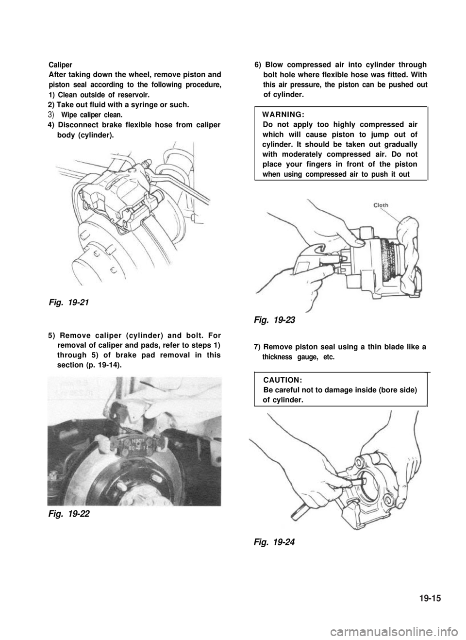
Caliper
After taking down the wheel, remove piston and
piston seal according to the following procedure,
1) Clean outside of reservoir.
2) Take out fluid with a syringe or such.
3)Wipe caliper clean.
4) Disconnect brake flexible hose from caliper
body (cylinder).
Fig. 19-21
6) Blow compressed air into cylinder through
bolt hole where flexible hose was fitted. With
this air pressure, the piston can be pushed out
of cylinder.
WARNING:
Do not apply too highly compressed air
which will cause piston to jump out of
cylinder. It should be taken out gradually
with moderately compressed air. Do not
place your fingers in front of the piston
when using compressed air to push it out
Fig. 19-23
5) Remove caliper (cylinder) and bolt. For
removal of caliper and pads, refer to steps 1)
through 5) of brake pad removal in this
section (p. 19-14).
Fig. 19-22
7) Remove piston seal using a thin blade like a
thickness gauge, etc.
CAUTION:
Be careful not to damage inside (bore side)
of cylinder.1
Fig. 19-24
19-15
Page 401 of 962
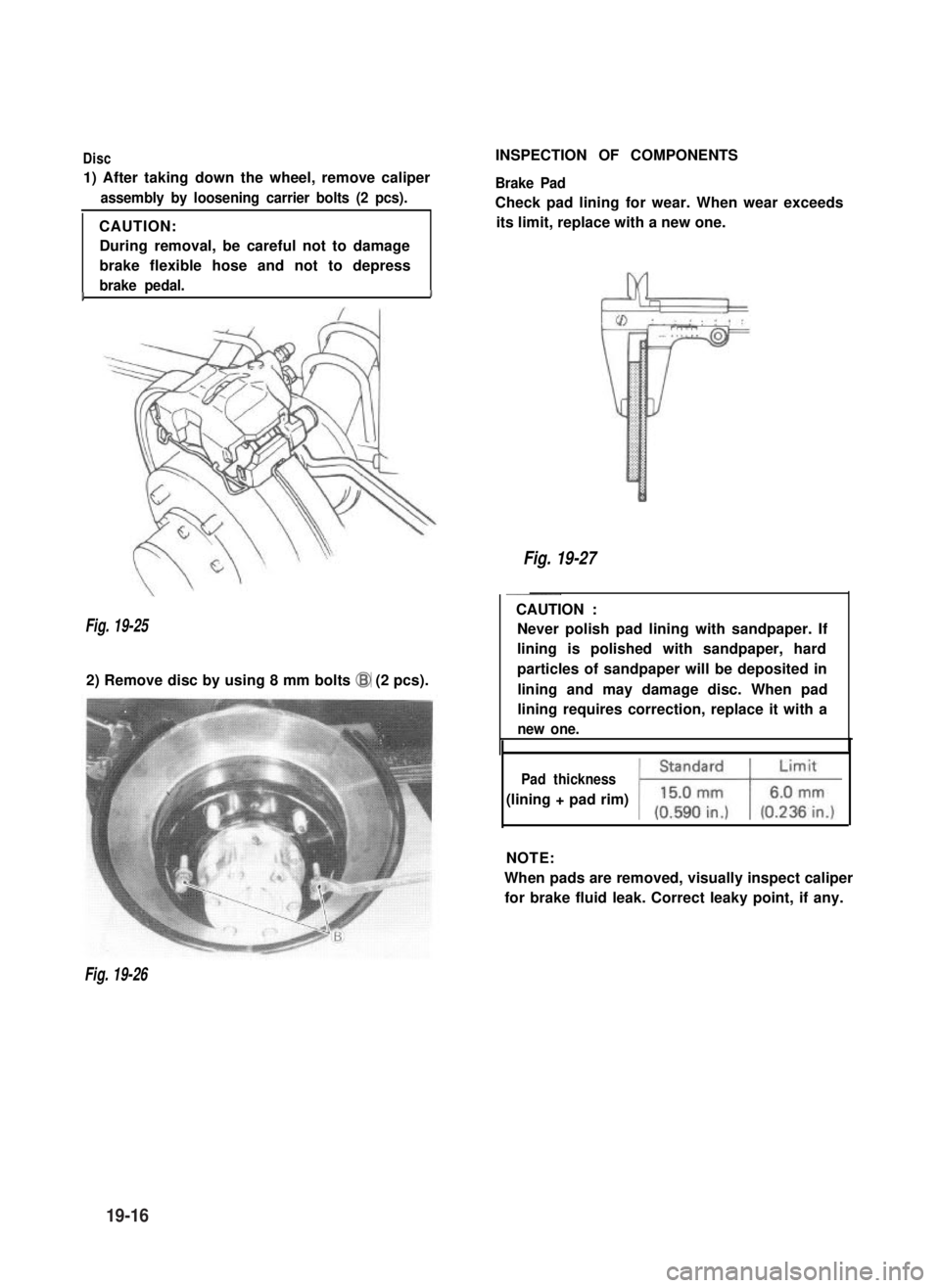
Disc
1) After taking down the wheel, remove caliper
assembly by loosening carrier bolts (2 pcs).
CAUTION:
During removal, be careful not to damage
brake flexible hose and not to depress
brake pedal.II
Fig. 19-25
2) Remove disc by using 8 mm bolts @I (2 pcs).
INSPECTION OF COMPONENTS
Brake Pad
Check pad lining for wear. When wear exceeds
its limit, replace with a new one.
Fig. 19-27
~~
CAUTION :
Never polish pad lining with sandpaper. If
lining is polished with sandpaper, hard
particles of sandpaper will be deposited in
lining and may damage disc. When pad
lining requires correction, replace it with a
new one.
Pad thickness
(lining + pad rim)
NOTE:
When pads are removed, visually inspect caliper
for brake fluid leak. Correct leaky point, if any.
Fig. 19-26
19-16