1987 SUZUKI GRAND VITARA check engine
[x] Cancel search: check enginePage 3 of 962
SECTION 0
GENERAL, SPECIAL TOOLS AND
SERVICE MATERIALS
CONTENTS
0-1. IDENTIFICATION NUMBER . . . . . . . . . . . . . . . . . . . . . . . . . . . . . . . . . O-1
0-2. STANDARD SHOP PRACTICES . . . . . . . . . . . . . . . . . . . . . . . . . . . . . . . O-2
0-3.SPECIAL TOOLS.. . . . . . . . . . . . 1.. . . . . . . . . . . . . . . . . . . . . . . . . . . . .
0-4.REQUIRED SERVICE MATERIALS . . . . . . . . . . . . . . . . . . . . . s . . . . . O-9
METRIC INFORMATION . . . . . . . . . . . . . . . . . . . . . , . . . . . . . . . . . . . O-12
O-l. IDENTIFICATION NUMBER
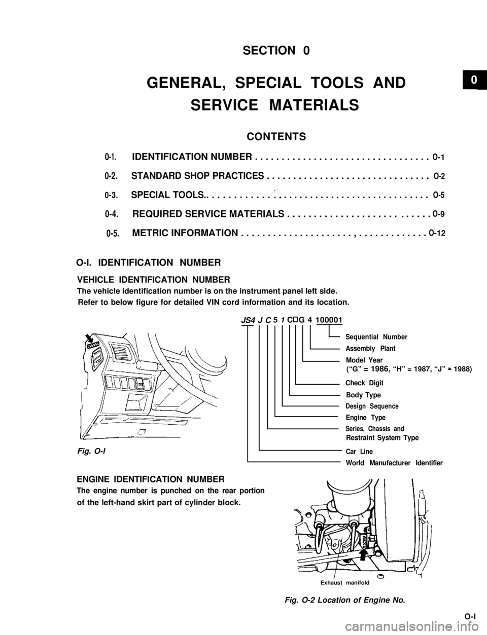
VEHICLE IDENTIFICATION NUMBER
The vehicle identification number is on the instrument panel left side.
Refer to below figure for detailed VIN cord information and its location.
5 1 C G 4 100001
Sequential Number
Assembly Plant
Model Year
(“G” = 1986, “H” = 1987, “J” = 1988)
Check Digit
Body Type
Design Sequence
Engine Type
Series, Chassis and
Restraint System Type
Car Line
World Manufacturer Identifier
Fig. O-l
ENGINE IDENTIFICATION NUMBER
The engine number is punched on the rear portion
of the left-hand skirt part of cylinder block.
Exhaust manifold
Fig. O-2 Location of Engine No.
O-l
JS4 J C
0-5.
O- 5
0
Page 21 of 962
![SUZUKI GRAND VITARA 1987 Service Repair Manual 1-2. ENGINE AND EMISSION CONTROL
1. WATER PUMP BELT INSPECTION
AND REPLACEMENT
[INSPECTION]
1) Disconnect negative battery lead at battery.
2) Inspect belt for cracks, cuts, deformation,
wear and clea SUZUKI GRAND VITARA 1987 Service Repair Manual 1-2. ENGINE AND EMISSION CONTROL
1. WATER PUMP BELT INSPECTION
AND REPLACEMENT
[INSPECTION]
1) Disconnect negative battery lead at battery.
2) Inspect belt for cracks, cuts, deformation,
wear and clea](/manual-img/20/57437/w960_57437-20.png)
1-2. ENGINE AND EMISSION CONTROL
1. WATER PUMP BELT INSPECTION
AND REPLACEMENT
[INSPECTION]
1) Disconnect negative battery lead at battery.
2) Inspect belt for cracks, cuts, deformation,
wear and cleanliness. If any defect, replace.
Check belt for tension. The belt is in’ proper
tension if it deflects 6 to 9 mm (0.24 - 0.35
in.) under thumb pressure (about 10 kg or
22 lb.)..
Belt tension6 - 9 mm (0.24 - 0.35 in.)
specificationas deflection
pulley
3) If the belt is too tight or too loose, adjust it
to specification by adjusting alternator
position.
4) Tighten alternator adjusting bolt and pivot
bolts.
5) Connect negative battery lead to battery.
[REPLACEMENT]
1) Disconnect negative battery lead at battery.
2) Loosen alternator adjusting bolt and pivot
bolts.
3) Replace water pump belt.
4) Adjust belt tension to specification and
tighten alternator adjusting bolt and pivot
bolts.
5) Connect negative battery lead to battery.
2. CAMSHAFT TIMING BELT INSPECTION
1) Disconnect negative battery lead at battery.
2) Loosen fan drive belt, and remove 4 bolts
securing radiator shroud panel and 4 nuts
securing engine cooling fan & clutch. Then
remove radiator shroud and cooling fan &
clutch at the same time.
3) Remove water pump belt and pump pulley.
4) Remove crankshaft pulley by removing 4
pulley bolts. The crankshaft timing belt
pulley bolt at the center need not be loosen-
ed.2 1
‘31. Key
2. Crankshaft pulley
3. Pulley bolt
1-5
Page 23 of 962
NOTE:
Steps 1) - 6) outlined above must be performed
with ENGINE NOT RUNNING. For step 7),
be sure to have adequate ventilation while
engine is running
It is recommended to use engine oil of SE or
SF class.
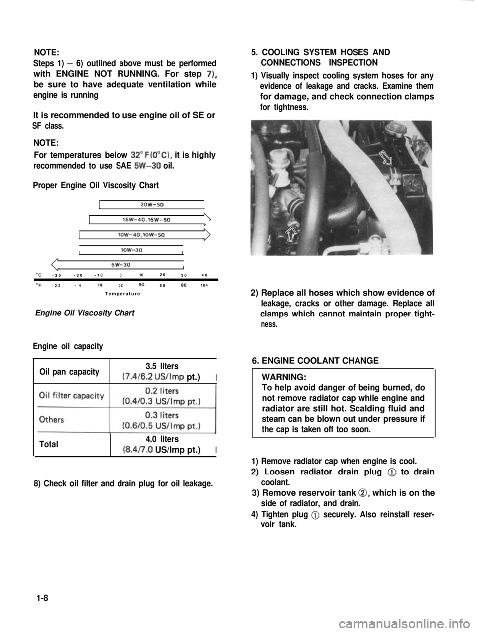
NOTE:For temperatures below
32”F(O”C), it is highly
recommended to use SAE 5W-30 oil.
Proper Engine Oil Viscosity Chart
12OW-50
lSW-40.15w-501
Ilow-4O.lOW-50
Ilow-30I
5w-30I“C-3 0 -2
0 -1
0 0 102
0
30 4
0
OF-2 2 -
4 14
32506886104
Temperatur e
Engine Oil Viscosity Chart
Engine oil capacity
Oil pan capacity 3.5 liters (7.4/6.2
US/Imp pt.)I
Total 4.0 liters(8.4/7.0 US/Imp pt.)I
8) Check oil filter and drain plug for oil leakage.
5. COOLING SYSTEM HOSES AND
CONNECTIONS INSPECTION
1) Visually inspect cooling system hoses for any
evidence of leakage and cracks. Examine them
for damage, and check connection clamps
for tightness.
2) Replace all hoses which show evidence of
leakage, cracks or other damage. Replace all
clamps which cannot maintain proper tight-
ness.
6. ENGINE COOLANT CHANGE
WARNING:
To help avoid danger of being burned, do
not remove radiator cap while engine and
radiator are still hot. Scalding fluid and
steam can be blown out under pressure if
the cap is taken off too soon.
1) Remove radiator cap when engine is cool.
2) Loosen radiator drain plug @
to drain
coolant.
3) Remove reservoir tank 0, which is on the
side of radiator, and drain.
4) Tighten plug
@ securely. Also reinstall reser-
voir tank.
1-8
Page 24 of 962
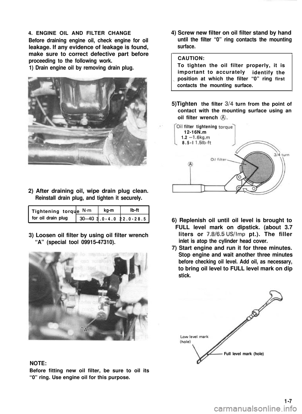
4. ENGINE OIL AND FILTER CHANGEBefore draining engine oil, check engine for oil
leakage. If any evidence of leakage is found,
make sure to correct defective part before
proceeding to the following work.
1) Drain engine oil by removing drain plug.
2) After draining oil, wipe drain plug clean.
Reinstall drain plug, and tighten it securely.
Tightening torque N-m kg-mlb-ft
for oil drain plug30-40 3.0-4.0 22.0-28.
5
3) Loosen oil filter by using oil filter wrench
“A” (special tool 09915-47310).
4) Screw new filter on oil filter stand by hand
until the filter “0” ring contacts the mounting
surface.
ICAUTION:
To tighten the oil filter properly, it is important to accurately identify the
1-position at which the filter “0” ring first
contacts the mounting surface.
5)Tighten the filter 3/4 turn from the point of
contact with the mounting surface using an
oil filter wrench
@.
filter tightening
12-16N.m
1.2
-1.6kg.m
8.5-l l.lilb-ft
6) Replenish oil until oil level is brought to
FULL level mark on dipstick. (about 3.7liters or 7.8/6.5
US/Imp pt.). The filler
inlet is atop the cylinder head cover.
7) Start engine and run it for three minutes.
Stop engine and wait another three minutes
before checking oil level. Add oil, as necessary,
to bring oil level to FULL level mark on dip
stick.
NOTE:
Before fitting new oil filter, be sure to oil its
“0” ring. Use engine oil for this purpose.
v
Full level mark (hole)
1-7
Page 25 of 962
CAUTION:
When changing engine coolant, use mixture
of 56% water and 50% GOLDEN CRUISER
1200for the market where ambient tem-
perature falls lower than -16°C (3°F) in
winter and mixture of 70% water and
30% GOLDEN CRUISER 1200for the
market where ambient temperature doesn’t
fall lower than -16°C (3” F).
Even in a market where no freezing tempe-
rature is anticipated, mixture of 70% water
and 30% GOLDEN CRUISER 1200
should be used for the purpose of corro-
sion protection and lubrication.
7. EXHAUST PIPES AND MOUNTINGS
INSPECTION
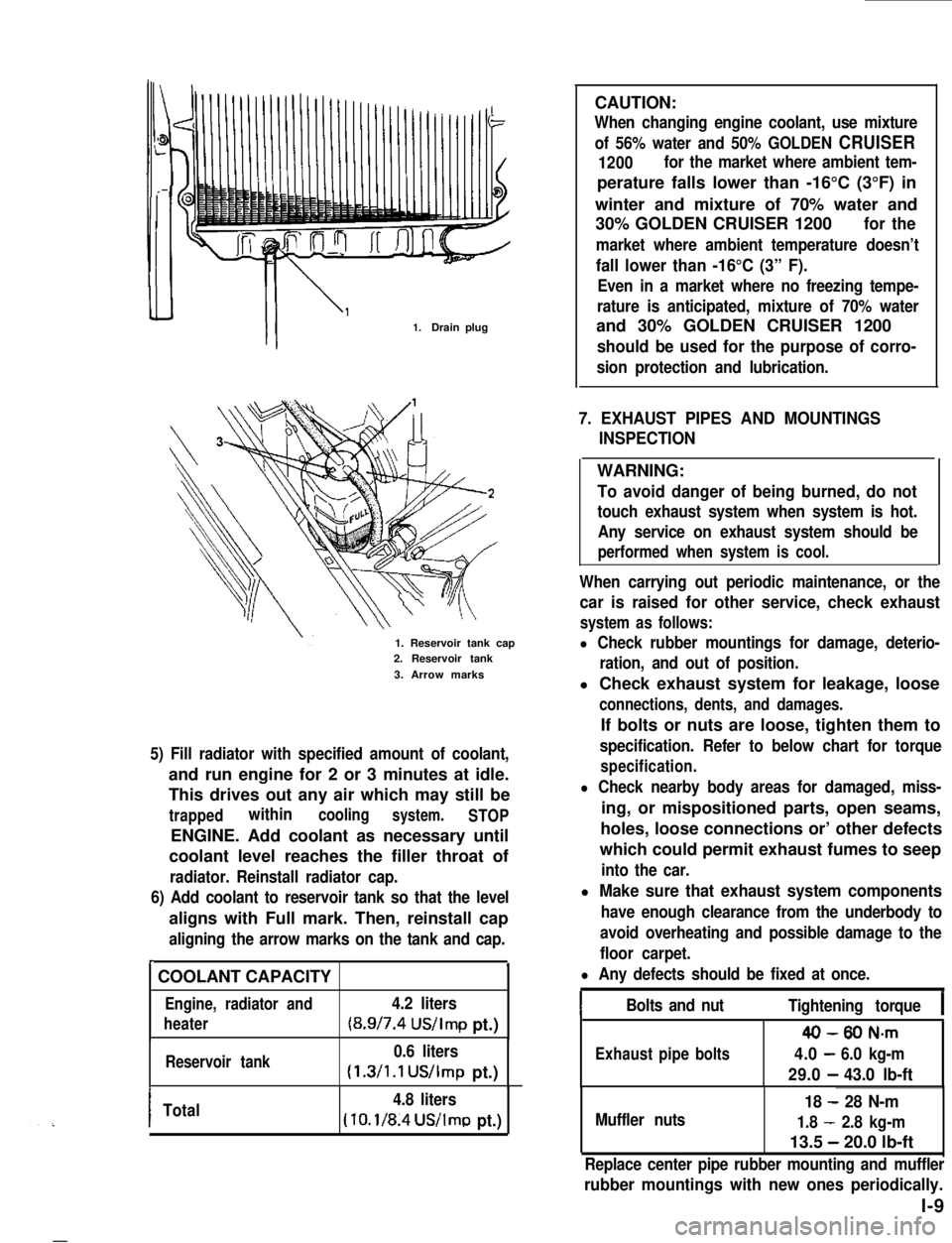
1.Drain plug
1. Reservoir tank cap2. Reservoir tank
3. Arrow marks
5) Fill radiator with specified amount of coolant,
and run engine for 2 or 3 minutes at idle.
This drives out any air which may still be
trappedwithincoolingsystem.STOP
ENGINE. Add coolant as necessary until
coolant level reaches the filler throat of
radiator. Reinstall radiator cap.
6) Add coolant to reservoir tank so that the level
aligns with Full mark. Then, reinstall cap
aligning the arrow marks on the tank and cap.
r.
COOLANT CAPACITY
Engine, radiator and4.2 liters
heater(8.9/7.4 US/Imp pt.)
Reservoir tank0.6 liters
(1.3/1.1 US/Imp pt.)
ITotal4.8 liters
(10.1/8.4US/lmp pt.)
WARNING:
To avoid danger of being burned, do not
touch exhaust system when system is hot.
Any service on exhaust system should be
performed when system is cool.
When carrying out periodic maintenance, or the
car is raised for other service, check exhaust
system as follows:
l Check rubber mountings for damage, deterio-
ration, and out of position.
l Check exhaust system for leakage, loose
connections, dents, and damages.
If bolts or nuts are loose, tighten them to
specification. Refer to below chart for torque
specification.
l Check nearby body areas for damaged, miss-
ing, or mispositioned parts, open seams,
holes, loose connections or’ other defects
which could permit exhaust fumes to seep
into the car.
l Make sure that exhaust system components
have enough clearance from the underbody to
avoid overheating and possible damage to the
floor carpet.
l Any defects should be fixed at once.
IBolts and nutTightening torqueI
40-80 N-m
Exhaustpipebolts4.0-6.0 kg-m
29.0-43.0 lb-ft
Muffler nuts
18 - 28 N-m
1.8 - 2.8 kg-m
13.5 - 20.0 lb-ft
Replace center pipe rubber mounting and muffler
rubber mountings with new ones periodically.
l-9
Page 26 of 962
8. PCV VALVE REPLACEMENT
1) Disconnect crankcase ventilation hose from
PCV valve.
2) Remove PCV valve from intake manifold.
3) Wind sealing tape on thread of the new valve
and install it securely.
Tightenlng torque
for PCV valve
15-25 N.m
1.5-2.5 kg-m,
11 .O-18.0 lb-ft
4) Install hose and clamp it securely.
9. OXYGEN SENSOR REPLACEMENT
[Canadian specification vehicle]
When the odometer indicates 50,000 and 100,000
miles, replace oxygen sensor as follows.
CAUTION:
To avoid the danger of being burned, do
not touch the exhaust system when the
system is hot. This work should be perform-
ed when the system is cool.
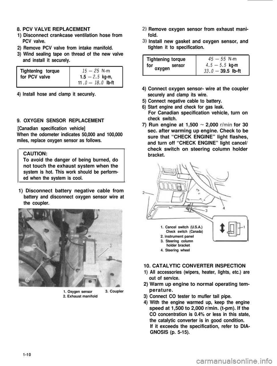
1) Disconnect battery negative cable from
battery and disconnect oxygen sensor wire at
the coupler.
1. Oxygen sensor
2. Exhaust manifold
3. Coupler
2) Remove oxygen sensor from exhaust mani-
fold.
3) Install new gasket and oxygen sensor, and
tighten it to specification.
-Tightening45torque55 N-m
4.5-foroxygensensor5.5 kg-m
33.0-39.5 lb-ft
4) Connect oxygen sensor- wire at the coupler
securely and clamp its wire.
5) Connect negative cable to battery.
6) Start engine and check for gas leak.
For Canadian specification vehicle, turn on
check switch.
7) Run engine at 1,500 - 2,000 r/min for 30
sec. after warming up engine. Check to be
sure that “CHECK ENGINE” light flashes,
and turn off “CHECK ENGINE” light cancel/
check switch on steering column holder
bracket.
1. Cancel switch (U.S.A.)Check switch (Canada)
2. instrument panel
3. Steering columnholder bracket
4. Steering wheel
10. CATALYTIC CONVERTER INSPECTION
1) All accessories (wipers, heater, lights, etc.) are
out of service.
2) Warm up engine to normal operating tem-
perature.
3) Connect CO tester to mufler tail pipe.
4) With the engine warmed up, keep the engine
speed at 1,500 to 2,000 r/min. (t-pm). If the
CO concentration is 0.4% or less in this state,
the catalytic converter is in good condition.
If it exceeds the specification, refer to DIA-
GNOSIS (p. 5-15).
1-10
Page 27 of 962
1. CHARCOAL CANISTER REPLACEMENT
WARNING:
The following cautions should be always
observed.
l Disconnect negative cable at battery.
l DO NOT smoke and place “NO SMOK-
ING” signs near work area.
l Be sure to have COZ fire extinguisher
handy.
l Wear safety glasses.
l To release the fuel vapor pressure in
fuel tank, remove the fuel tank cap and
then reinstall it.
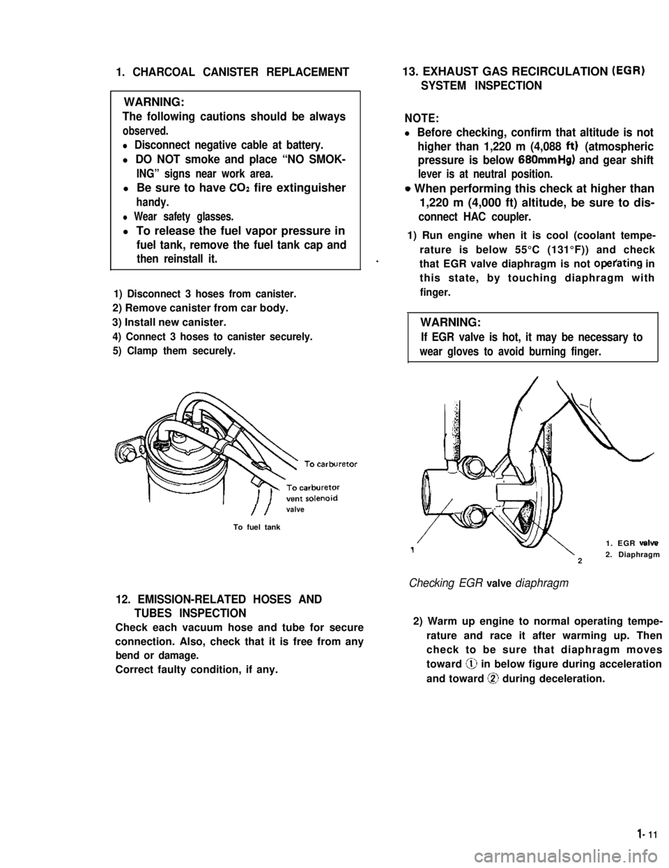
1) Disconnect 3 hoses from canister.
2) Remove canister from car body.
3) Install new canister.
4) Connect 3 hoses to canister securely.
5) Clamp them securely.
//valve
To fuel tank
12. EMISSION-RELATED HOSES AND
TUBES INSPECTION
Check each vacuum hose and tube for secure
connection. Also, check that it is free from any
bend or damage.
Correct faulty condition, if any.
13. EXHAUST GAS RECIRCULATION (EGR)
SYSTEM INSPECTION
NOTE:
l Before checking, confirm that altitude is not
higher than 1,220 m (4,088 ftt) (atmospheric
pressure is below 680mmHg) and gear shift
lever is at neutral position.
o When performing this check at higher than
1,220 m (4,000 ft) altitude, be sure to dis-
connect HAC coupler.
.
1) Run engine when it is cool (coolant tempe-
rature is below 55°C (131°F)) and check
that EGR valve diaphragm is not operating in
this state, by touching diaphragm with
finger.
WARNING:
If EGR valve is hot, it may be necessary to
wear gloves to avoid burning finger.
1. EGR valve
22. Diaphragm
Checking EGR valve diaphragm
2) Warm up engine to normal operating tempe-
rature and race it after warming up. Then
check to be sure that diaphragm moves
toward @ in below figure during acceleration
and toward @ during deceleration.
l- 11
Page 28 of 962
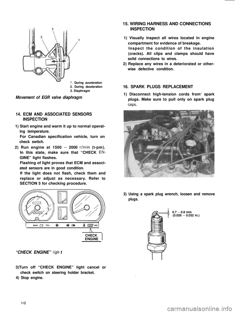
1. During acceleration
2. During deceleration
3. Diaphragm
Movement of EGR valve diaphragm
14. ECM AND ASSOCIATED SENSORS
INSPECTION
1) Start engine and warm it up to normal operat-
ing temperature.
For Canadian specification vehicle, turn on
check switch.
2) Run engine at 1500 - 2000 r/min (t-pm).
In this state, make sure that “CHECK EON-
GINE” light flashes.
Flashing of light proves that ECM and associ-
ated sensors are in good condition.
If the light does not flash, check them and
replace or adjust as necessary. Refer to
SECTION 5 for checking procedure.
A
CHECKENGINE
“CHECK ENGINE” ligh t
3)Turn off “CHECK ENGINE” light cancel or
check switch on steering holder bracket.
4) Stop engine.
15. WIRING HARNESS AND CONNECTIONS
INSPECTION
1) Visually inspect all wires located in engine
compartment for evidence of breakage.
Inspect the condition of the insulation
(cracks). All clips and clamps should have
solid connections to wires.
2) Replace any wires in a deteriorated or other-
wise defective condition.
16. SPARK PLUGS REPLACEMENT
1) Disconnect high-tension cords from‘ spark
plugs. Make sure to pull only on spark plug
caps.
2) Using a spark plug wrench, loosen and remove
plugs.
0.7 - 0.8 mm(0.028 - 0.032 in.)
1-12