1987 SUZUKI GRAND VITARA tire pressure
[x] Cancel search: tire pressurePage 34 of 962
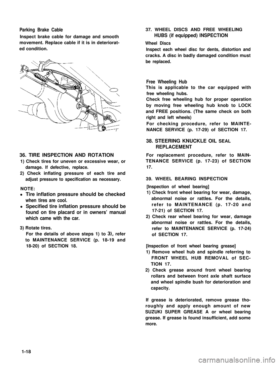
Parking Brake Cable
Inspect brake cable for damage and smooth
movement. Replace cable if it is in deteriorat-
ed condition.
36. TIRE INSPECTION AND ROTATION
1) Check tires for uneven or excessive wear, or
damage. If defective, replace.
2) Check inflating pressure of each tire and
adjust pressure to specification as necessary.
NOTE:
l Tire inflation pressure should be checked
when tires are cool.
l Specified tire inflation pressure should be
found on tire placard or in owners’ manual
which came with the car.
3) Rotate tires.
For the details of above steps 1) to 3), refer
to MAINTENANCE SERVICE (p. 18-19 and
18-20) of SECTION 18.
37. WHEEL DISCS AND FREE WHEELING
HUBS (if equipped) INSPECTION
Wheel Discs
Inspect each wheel disc for dents, distortion and
cracks. A disc in badly damaged condition must
be replaced.
Free Wheeling Hub
This is applicable to the car equipped with
free wheeling hubs.
Check free wheeling hub for proper operation
by moving free wheeling hub knob to LOCK
and FREE positions. (The same check on both
right and left wheels)
For checking procedure, refer to MAINTE-
NANCE SERVICE (p. 17-29) of SECTION 17.
38. STEERING KNUCKLE OIL SEAL
REPLACEMENT
For replacement procedure, refer to MAIN-
TENANCE SERVICE (p. 17-23) of SECTION
17.
39. WHEEL BEARING INSPECTION
[Inspection of wheel bearing]
1) Check front wheel bearing for wear, damage,
abnormal noise or rattles. For the details,
refer to MAINTENANCE (p. 17-20 and
17-21) of SECTION 17.
2) Check rear wheel bearing for wear, damage
abnormal noise or rattles. For the details,
refer to MAINTENANCE SERVICE (p. 17-24)
of SECTION 17.
[Inspection of front wheel bearing grease]
1) Remove wheel hub and spindle referring to
FRONT WHEEL HUB REMOVAL of SEC-
TION 17.
2) Check grease around front wheel bearing
rollars and between front axle shaft surface
and wheel spindle bush for deterioration and
capacity.
If grease is deteriorated, remove grease tho-
roughly and apply enough amount of new
SUZUKI SUPER GREASE A or wheel bearing
grease. If grease is found insufficient, add some
more.
1-18
Page 46 of 962

ConditionPossible causeCorrection
High fuel consumptionAbnormal condition ignition system
1. Improper ignition timingAdjust
2. Leak or loose connection of high tension cordRepair or replace
3. Defective spark plug (improper gap, heavyClean, adjust or replace
deposits, and burned electrodes, etc..)
4. Cracked distributor cap or rotorReplace
5. Malfunctioning mechanical and vacuumCheck and repair or
advancers in distributorreplace
Abnormal condition in fuel system
1. Improper float levelAdjust
2. Fuel leakage from tank, pipe or carburetorRepair or replace
3. Malfunctioning carburetor choke systemRepair or replace
4. Dirty or clogged carburetor jetsClean
5. Clogged air cleaner elementClean or replace
6. Malfunctioning thermostatically controlledCheck and repair or
air cleanerreplace
Abnormal condition in engine
1. Low compressionPreviously outlined
2. Poor valve seatingRepair or replace
3. Improper valve clearanceAdjust
Emission control
1. Air leaks at exhaust manifoldTighten manifold bolts
and nuts.
Replace gasket.
2. Oxygen sensor out of orderReplace.
3. Water temperature switch out of orderReplace.
4. Malfunctioning throttle position switchReplace
5. Malfunctioning MCS (mixture controlReplace
solenoid) valve in carburetor
6. Malfunctioning EGR valveReplace
Others
1. Dragging brakesRepair or replace
2. Slipping clutchAdjust or replace
3. Improper tire pressureAdjust
Excessive engine oilOil leakage
consumption1. Loose oil drain plugTighten
2. Loose oil pan securing boltsTighten
3. Deteriorated or broken oil pan sealantReplace sealant
4. Leaky oil sealsReplace
5. Blown cylinder head gasketReplace
6. Improper tightening of oil filterTighten
7. Loose oil pressure switchTighten
2-8
Page 52 of 962

2-9. SUSPENSION, STEERING SYSTEM AND TIRES
Condition
Hard steering
Possible causeCorrection
1. Wheel tires not adequately inflatedAdjust the pressure
2. Bind in tie rod end ball studReplace
3. Linkage connections tending to seizeRepair or replace
4. Steering gearbox out of adjustmentAdjust as prescribed
5. Unevenly worn steering shaft bushReplace
6. Disturbed front wheel alignmentAdjust as prescribed
Wobbly steering wheel1. Wheel tires inflated unequallyAdjust tire pressure
(Shimmy, shake or2. Wobbly wheelsRepair or replace
vibration)3. Large difference in tire diameter betweenReplace._
right and left wheels
4. Loose hub nutsRetighten
5. Damaged or worn wheel bearingsReplace
6. Worn or loose tie rod endsReplace or retighten
7. Steering gearbox out of adjustmentAdjust as prescribed
8. Steering gearbox mounted looseRetighten
9. Worn steering knuckle oil sealReplace
10. Tire or wheel out of balanceBalance wheel or replace tire
and/or wheel
11. Blister or bump on tireReplace tire
12. Disturbed front wheel alignmentCheck front wheel alignment
Steering wheel
pulling to one
side (car pulls)
1. Unevenly worn wheel tires
2. Brake dragging in one road wheel
3. Wheel tires unequally inflated
4. Worn or distorted link rods
5. Disturbed front wheel alignment
6. Loose, bent or broken front or rear
suspension parts
Replace
Repair
Adjust tire pressure
Replace
Adjust as prescribed
Tighten or replace suspension
parts
Shocks coming to1. Tire inflating pressure too highReduce to the specification
steering wheel2. Poor shock absorber performanceReplace
(or wheel tramp)3. Differences in tire diameter among fourAdjust
road wheels
4. Worn steering linkage connectionsReplace
5. Worn or broken front wheel bearingsReplace
6. Loose front wheelRetighten
7. Steering wheel loose in placeRetighten the nut
8. Blister or bump on tireReplace tire
Rapid wear or uneven1. Wheel tires imporperly inflatedAdjust tire pressure
wear of wheel tires2. Differences in diameter among four tiresAdjust or replace
(Abnormal or excessive3. Worn or loose road wheel bearingsReplace
tire wear)4. Wobbly wheel tiresRepair or replace
2-14
Page 53 of 962

ConditionPossible causeCorrection
Rapid wear or uneven5. Wheel tires improperly “rotated“ toAdjust
wear of wheel tiresresult in unbalance
(Abnormal or excessive6. Disturbed front wheel alignmentAdjust as prescribed
tire wear)7. Hard drivingReplace tire
Steering noise1. Loose bolts and nuts
2. Loose leaf spring seats
3. Broken or otherwise damaged wheel
bearings
4. Worn or sticky tie rod ends
5. Linkage joints needling grease
Retighten
Retighten
Replace
Replace
Lubricate or replace
Too much play in
steering
1. Worn wheel bearings .Replace wheel bearing
2. Steering gear box attachments looseTighten or repair
3. Steering gear box adjustmentsCheck and adjust
4. Worn steering shaft jointsReplace joint
5. Worn tie rod ends or drug rod ball jointsReplace tie rod end or tie rod
Poor returnability1. Bind in tie rod end ball studs
2. Bind in steering column
3. Lack of lubricant steering gear box
4. Disturbed front end alignment
5. Steering gear box adjustment
6. Tires not adequatley inflated
Replace tie rod end
Repair or replace
Check, lubricate or replace
Check and adjust front end
alignment
Check and adjust gear box
torque
Adjust pressure
Abnormal noise,
front end
1. Worn, sticky or loose tie rod ends, drug
rod ball joints or axle shaft joints
2. Damaged shock absorbers or mountings
3. Loose stabilizer bar
4. Loose wheel nuts
5. Loose suspension bolts or nuts
6. Broken or otherwise damaged wheel
bearings
7. Broken suspension springs
Replace tie rod ends, drug
rod or axle shaft joints
Replace or repair
Tighten bolts or replace bushe!
Tighten
Tighten suspension bolts or
nuts
Replace
Replace
Wander or poor
steering stability
1. Mismatched or uneven tires
2. Loose tie rod ends or drug rod
3. Faulty shock absorber or mounting
Replace tire or inflate tires to
proper pressure
Replace tie rod end or drug ro(
Replace absorber or repair
mounting
2-15
Page 380 of 962
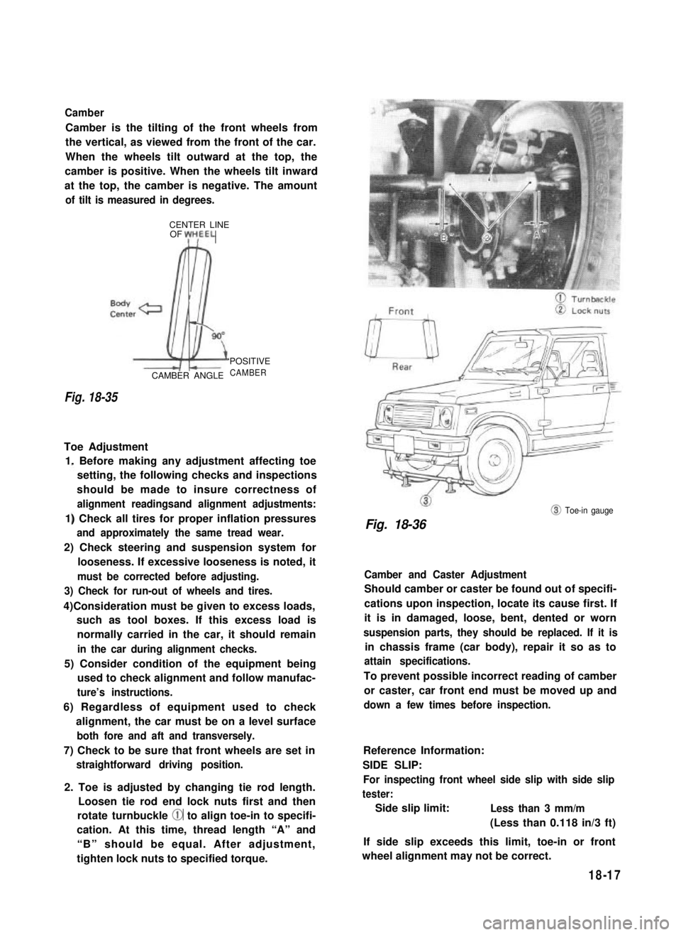
Camber
Camber is the tilting of the front wheels from
the vertical, as viewed from the front of the car.
When the wheels tilt outward at the top, the
camber is positive. When the wheels tilt inward
at the top, the camber is negative. The amount
of tilt is measured in degrees.
CENTER LINEOF yH,EEL
Fig. 18-35
CAMBER ANGLE
‘POSITIVE
CAMBER
Toe Adjustment
1. Before making any adjustment affecting toe
setting, the following checks and inspections
should be made to insure correctness of
alignment readingsand alignment adjustments:
1) Check all tires for proper inflation pressures
and approximately the same tread wear.
2) Check steering and suspension system for
looseness. If excessive looseness is noted, it
must be corrected before adjusting.
3) Check for run-out of wheels and tires.
4)Consideration must be given to excess loads,
such as tool boxes. If this excess load is
normally carried in the car, it should remain
in the car during alignment checks.
5) Consider condition of the equipment being
used to check alignment and follow manufac-
ture’s instructions.
6) Regardless of equipment used to check
alignment, the car must be on a level surface
both fore and aft and transversely.
7) Check to be sure that front wheels are set in
straightforward driving position.
2. Toe is adjusted by changing tie rod length.
Loosen tie rod end lock nuts first and then
rotate turnbuckle @ to align toe-in to specifi-
cation. At this time, thread length “A” and
“B” should be equal. After adjustment,
tighten lock nuts to specified torque.
@ Toe-in gauge
Fig. 18-36
Camber and Caster Adjustment
Should camber or caster be found out of specifi-
cations upon inspection, locate its cause first. If
it is in damaged, loose, bent, dented or worn
suspension parts, they should be replaced. If it is
in chassis frame (car body), repair it so as to
attain specifications.
To prevent possible incorrect reading of camber
or caster, car front end must be moved up and
down a few times before inspection.
Reference Information:
SIDE SLIP:
For inspecting front wheel side slip with side slip
tester:
Side slip limit:Less than 3 mm/m
(Less than 0.118 in/3 ft)
If side slip exceeds this limit, toe-in or front
wheel alignment may not be correct.
18-17
Page 382 of 962
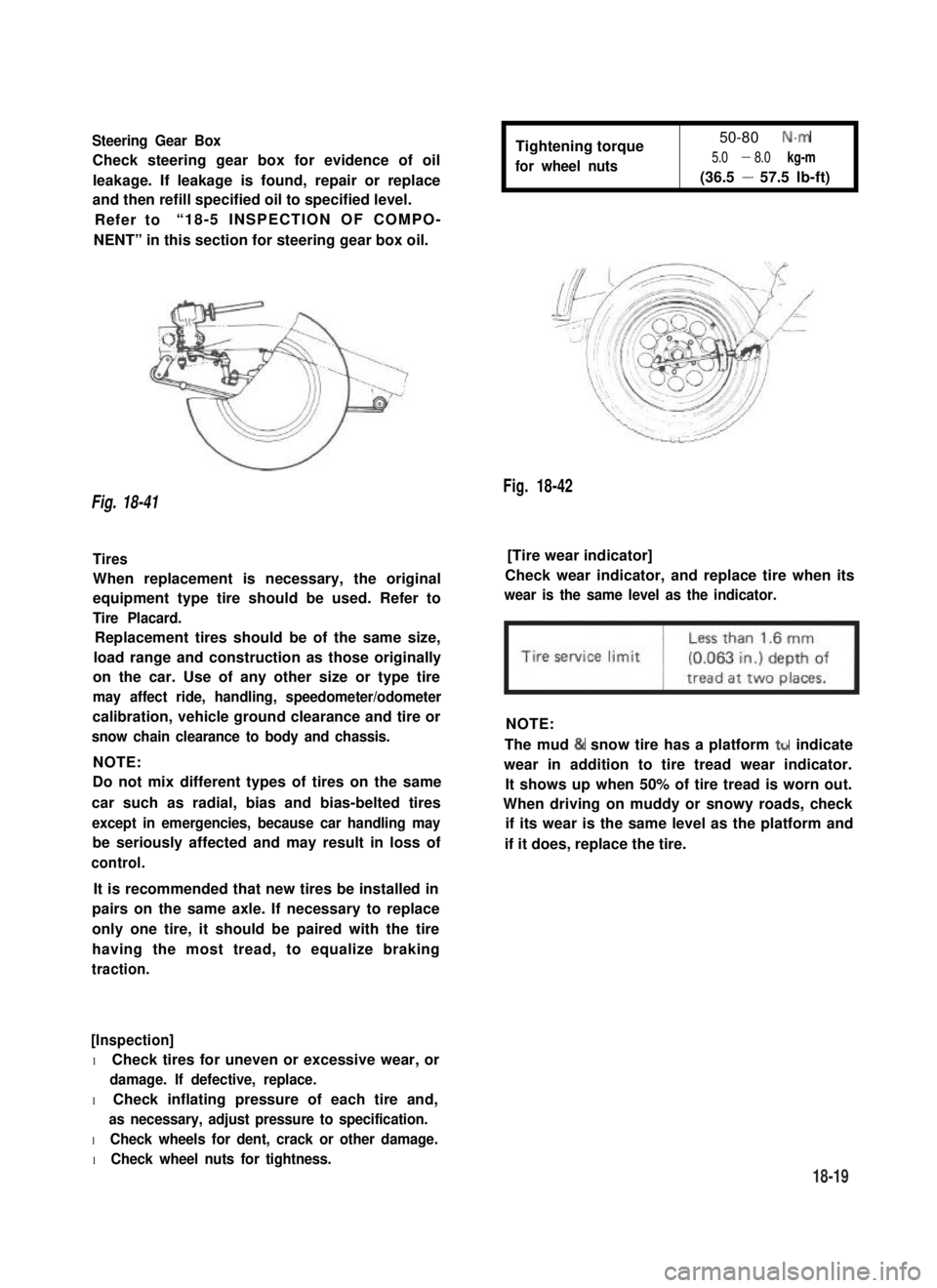
Steering Gear Box
Check steering gear box for evidence of oil
leakage. If leakage is found, repair or replace
and then refill specified oil to specified level.
Refer to“18-5 INSPECTION OF COMPO-
NENT” in this section for steering gear box oil.
Tightening torque
for wheel nuts
50-80 N.m
5.0 - 8.0 kg-m
(36.5 - 57.5 lb-ft)
Fig. 18-42
Fig. 18-41
Tires[Tire wear indicator]
When replacement is necessary, the original
equipment type tire should be used. Refer to
Tire Placard.
Check wear indicator, and replace tire when its
wear is the same level as the indicator.
Replacement tires should be of the same size,
load range and construction as those originally
on the car. Use of any other size or type tire
may affect ride, handling, speedometer/odometer
calibration, vehicle ground clearance and tire or
snow chain clearance to body and chassis.
NOTE:
NOTE:
Do not mix different types of tires on the same
car such as radial, bias and bias-belted tires
except in emergencies, because car handling may
be seriously affected and may result in loss of
control.
The mud & snow tire has a platform ttr indicate
wear in addition to tire tread wear indicator.
It shows up when 50% of tire tread is worn out.
When driving on muddy or snowy roads, check
if its wear is the same level as the platform and
if it does, replace the tire.
It is recommended that new tires be installed in
pairs on the same axle. If necessary to replace
only one tire, it should be paired with the tire
having the most tread, to equalize braking
traction.
[Inspection]
l Check tires for uneven or excessive wear, or
damage. If defective, replace.
l Check inflating pressure of each tire and,
as necessary, adjust pressure to specification.
l Check wheels for dent, crack or other damage.
l Check wheel nuts for tightness.
18-19
Page 383 of 962
![SUZUKI GRAND VITARA 1987 Service Repair Manual Fig. 18-43 @ Tire tread wear indicator
@ Wear indicating platform
[ Inflation of tires]
l Tire inflation pressures are listed on the
Tire Placard at driver’s side of instrument
panel.
l Tire inflati](/manual-img/20/57437/w960_57437-382.png "SUZUKI GRAND VITARA 1987 Service Repair Manual Fig. 18-43 @ Tire tread wear indicator
@ Wear indicating platform
[ Inflation of tires]
l Tire inflation pressures are listed on the
Tire Placard at driver’s side of instrument
panel.
l Tire inflati")
Fig. 18-43 @ Tire tread wear indicator
@ Wear indicating platform
[ Inflation of tires]
l Tire inflation pressures are listed on the
Tire Placard at driver’s side of instrument
panel.
l Tire inflation pressures should be checked
(including spare tire) at least monthly and
when significantly changing the load in the
car.
l Always check tire inflation pressures when
tires are “cold”.
l Always use tire pressure gauge when checking
inflation pressure.
l Be sure to reinstall tire inflation valve caps to
prevent dirt and moisture from getting into
valve core, as they may cause air leakage.
l If air loss occurs while driving, do not drive
on the deflated tire more than is needed to
stop safety. Driving even a short distance on a
deflated tire can damage a tire and wheel
beyond repair.
NOTE:
Before installing wheels, remove any build-up of
corrosion on the wheel mounting surface and
brake drum or disc mounting surface by scraping
and wire brushing. Installing wheels without
good metal-to-metal contact at the mounting
surfaces can cause wheel nuts to loosen, which
can later allow a wheel to come off while the
car is moving.
RADIAL TIRES
.i II
9T
\
I
4-wheels
Fig. 18-44
fT
u
[I
5-wheels
[Wheels]
Wheels must be replaced if they are bent, dented,
have excessive lateral or radial runout, leak air
through welds, have elongated bolt holes, if
lug nuts won’t stay tight, or if they are heavily
rusted. Wheels with greater runout than shown
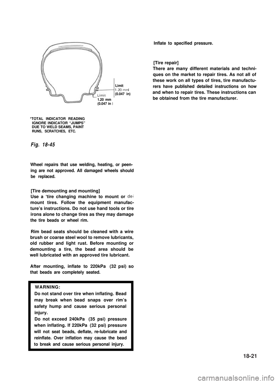
in below figure may cause objectional vibrations.
Replacement wheels must be equivalent to the
original equipment wheels in load capacity,
diameter,rim width, offset and mounting
configuration. A wheel of improper size or type
may affect wheel and bearing life, brake cooling,
speedometer/odometer calibration, car ground
clearance and tire clearance to the body and
chassis.
[Tire rotation]
“Rotate” tires at the regular intervals in order to
equalize tire wear and thereby make full use of
each tire. Refer to below figure for the scheme
of rotation. Adherence to this scheme prolongs
tire life.
18-20
Page 384 of 962
/I
d-
Limitl.Mmm(0.047 in)
1.20 mm(0.047 in 1
*TOTAL INDICATOR READINGIGNORE INDICATOR “JUMPS”DUE TO WELD SEAMS, PAINTRUNS, SCRATCHES, ETC.
Fig. 18-45
Wheel repairs that use welding, heating, or peen-
ing are not approved. All damaged wheels should
be replaced.
[Tire demounting and mounting]
Use a ‘tire changing machine to mount or de-
mount tires. Follow the equipment manufac-
ture’s instructions. Do not use hand tools or tire
irons alone to change tires as they may damage
the tire beads or wheel rim.
Rim bead seats should be cleaned with a wire
brush or coarse steel wool to remove lubricants,
old rubber and light rust. Before mounting or
demounting a tire, the bead area should be
well lubricated with an approved tire lubricant.
After mounting, inflate to 220kPa (32 psi) so
that beads are completely seated.
WARNING:
Do not stand over tire when inflating. Bead
may break when bead snaps over rim’s
safety hump and cause serious personal
injury.
Do not exceed 240kPa (35 psi) pressure
when inflating. If 220kPa (32 psi) pressure
will not seat beads, deflate, re-lubricate and
reinflate. Over inflation may cause the bead
to break and cause serious personal injury.1
Inflate to specified pressure.
[Tire repair]
There are many different materials and techni-
ques on the market to repair tires. As not all of
these work on all types of tires, tire manufactu-
rers have published detailed instructions on how
and when to repair tires. These instructions can
be obtained from the tire manufacturer.
18-21