1987 SUZUKI GRAND VITARA height adjustment
[x] Cancel search: height adjustmentPage 33 of 962

1-3. CHASSIS AND BODY
30. CLUTCH PEDAL INSPECTION
1) Check clutch pedal height. It should be the
same as brake pedal height.
2) Check clutch pedal free travel.
Clutch pedal free travel20 - 30 mm
(0.8 - 1.1 in.)
For the details of the above steps 1) and 2),
refer to MAINTENANCE SERVICE (p. 11-8) of
SECTION 11.
31. BRAKE DISCS, PADS, BRAKE DRUMS
AND SHOES INSPECTION
Brake Discs and Pads
I) Remove wheel and caliper but don’t discon-
nect brake hose from caliper.
2) Check front disc brake pads and discs for
excessivewear,damageand deflection.
Replace parts as necessary. For the details,
refer to p. 19-I 6 and 19-I 7 of SECT ION 19.
Be sure to torque caliper guide pins to specifi-
cation for reinstallation.
Brake Drums and Shoes
I) Remove wheel and brake drum.
2) Check rear brake drums and brake linings for
excessive wear and damage, while wheels and
drums are removed. Also check wheel cylin-
ders for leaks, at the same time. Replace
these parts as necessary.
For the details, refer to p. 19-21 and p. 19-
22 of SECTION 19.
32. BRAKE HOSES AND PIPES INSPECTION
Check brake hoses and pipes for proper hook-
up, leaks, cracks, chafing and other damage.
Replace any of these parts as necessary.
CAUTION:
After replacing any brake pipe or hose, be
sure to carry out air purge operation.
33. BRAKE FLUID INSPECTION AND
CHANGE
[INSPECTION]
1) Check around master cylinder and reservoir
for fluid leakage.
If found leaky, correct.
2) Check fluid level
If fluid level is lower than the minimum level
of reservoir, refilling is necessary. Fill reservoir
with specified brake fluids.
Brake fluid Speifi;t3ons
For the details, refer to MAINTENANCE
SERVICE (p. 19-42) of SECTION 19.
CAUTION:
Since the brake system of this car is factory-
filled with glycol-base brake fluid, do not
use or mix different type of fluid when
refilling the system; otherwise serious
damage will occur. Do not use old or used
brake fluid, or one taken from unsealed
container.
[CHANGE]
1) Change brake fluid. As fluid change procedure,
drain existing fluid from brake system com-
pletely, fill the system with above recom-
mended fluid and carry out air purge opera-
tion.
For description of air purge, refer to p. 19-46
and 19-47 of SECTION 19.
34. BRAKE PEDAL INSPECTION
Check brake pedal travel.
For -checking procedure, refer to PEDAL TRA-
VEL CHECK (p. 19-43) of SECTION 19.
35. BRAKE LEVER AND CABLE
INSPECTION
Parking Brake Lever
I) Check tooth tip of each notch for damage or
wear. If any damage or wear is found, replace
parking lever.
2) Check parking brake lever for proper opera-
tion and stroke, and adjust it if necessary.
For checking and adjusting procedures,
refer to PARKING BRAKE INSPECTION
AND ADJUSTMENT (p. 19-44) of SECTION
19.
1-17
Page 54 of 962

Condition
Wander or poor
steering stability
Low or uneven trim
height
Ride too soft
Suspension bottoms
Body leans or sways
in corners
Possible cause
4. Loose stabilizer bar
5. Broken or sagging springs
6. Steering gear box adjustment
7. Front wheel alignment
1. Broken or sagging springs
2. Overloaded
3. Incorrect springs
1. Faulty shock absorbers
1. Overloaded
2. Faulty shock absorbers
3. Incorrect, broken or sagging springs
1. Loose stabilizer bar
2. Faulty shock absorbers or mounting
3. Broken or sagging springs
4. Overloaded
Correction
Tighten or replace stabilizer
bar or bushs
Replace spring
Check or adjust steering gear
box torque
Check front wheel alignment
Replace
Check loading
Replace
Replace
Checking loading.
Replace
Replace
Tighten stabilizer bar bolts or
replace bushes
Replace shock absorbers or
tighten mounting
Replace
Check loading
STARTING MOTOR
Condition
Starter runs but
pinion will not mesh
into ring gear.
Starter will not run
at all, or runs but
runs too slow to
crank with full
force.
Possible cause
1. Worn pinion of starter clutch.
2. Defective splines resulting in sticky
pinion plunging motion.
3. Worn bush.
4. Wrong pinion plunging position.
5. Worn teeth of ring gear.
Battery trouble
1, Poor contact in battery terminal
connection
2. Loose ground cable connection
3. Battery run down
4. Battery voltage too low due to battery
deterioration
Correction
Replace.
Repair or replace.
Replace.
Adjust
Replace.
Repair or retighten
Retighten
Recharge
Replace
Ignition switch trouble
1. Poor contacting actionReplace
2. Lead wire socket loose in placeRetighten
3. Opne-circuit between ignition switch andRepair
magnet switch
2-10.
2-16
Page 135 of 962

Float Adjustment
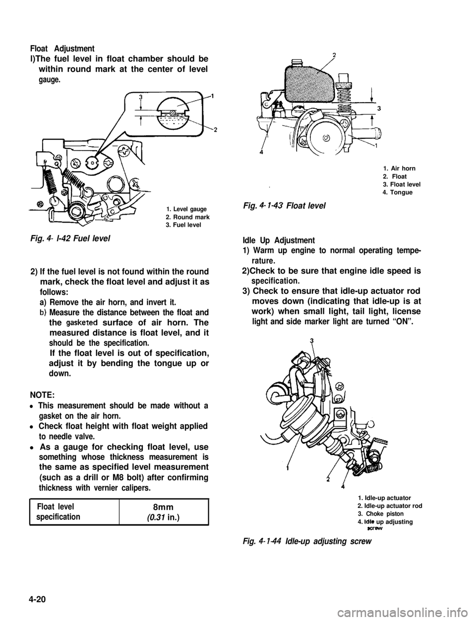
l)The fuel level in float chamber should be
within round mark at the center of level
gauge.
1. Level gauge
2. Round mark3. Fuel level
Fig. 4- l-42 Fuel level
2) If the fuel level is not found within the round
mark, check the float level and adjust it as
follows:
a) Remove the air horn, and invert it.
b) Measure the distance between the float and
the gasketed surface of air horn. The
measured distance is float level, and it
should be the specification.
If the float level is out of specification,
adjust it by bending the tongue up or
down.
NOTE:
l This measurement should be made without a
gasket on the air horn.
l Check float height with float weight applied
to needle valve.
l As a gauge for checking float level, use
something whose thickness measurement is
the same as specified level measurement
(such as a drill or M8 bolt) after confirming
thickness with vernier calipers.
Float level8mm
specification(0.31 in.)
.
Fig. 4- l-43 Float level
1. Air horn
2. Float
3. Float level
4. Tongue
Idle Up Adjustment
1) Warm up engine to normal operating tempe-
rature.
2)Check to be sure that engine idle speed is
specification.
3) Check to ensure that idle-up actuator rod
moves down (indicating that idle-up is at
work) when small light, tail light, license
light and side marker light are turned “ON”.
1. Idle-up actuator
2. Idle-up actuator rod
3. Choke piston
4. Idle up adjustingsorew
Fig. 4- l-44 Idle-up adjusting screw
4-20
Page 428 of 962

BRAKE PEDAL FREE HEIGHT ADJUSTMENT
Brake pedal height is normal if brake pedal is
as high as clutch pedal.
1) When booster push rod clevis has been
reinstalled, it is important that measurement
between booster mounting surface (with a
gasket attached) and the center of clevis
pin hole is adjusted within 125.5 mm -
126.5 mm (4.94 - 4.98 in.). (See page
19-37.)
2) When stop light switch has been removed,
refer to the following STOP LIGHT SWITCH
ADJUSTMENT for proper installation.
The services in above steps 1) and 2) may
affect brake pedal height.
STOP LIGHT SWITCH ADJUSTMENT
Adjustment should be made as follows when
installing the switch.
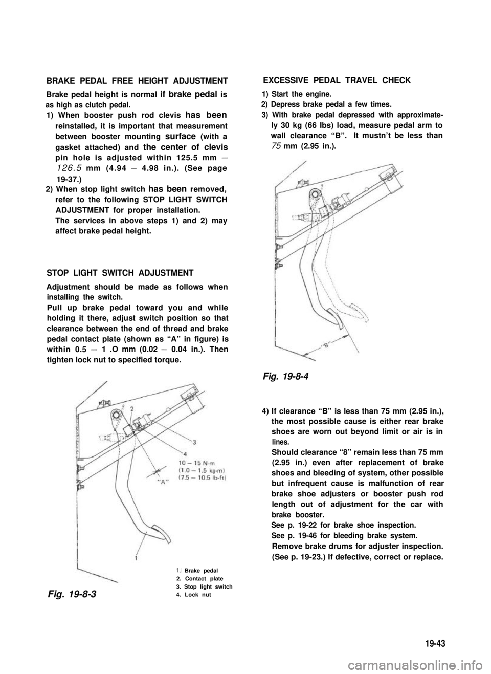
Pull up brake pedal toward you and while
holding it there, adjust switch position so that
clearance between the end of thread and brake
pedal contact plate (shown as “A” in figure) is
within 0.5 -1 .O mm (0.02 - 0.04 in.). Then
tighten lock nut to specified torque.
1. Brake pedal
2. Contact plate
3. Stop light switch4. Lock nut
EXCESSIVE PEDAL TRAVEL CHECK
1) Start the engine.
2) Depress brake pedal a few times.
3) With brake pedal depressed with approximate-
ly 30 kg (66 Ibs) load, measure pedal arm to
wall clearance “B”.It mustn’t be less than
75 mm (2.95 in.).
Fig. 19-8-4
4) If clearance “B” is less than 75 mm (2.95 in.),
the most possible cause is either rear brake
shoes are worn out beyond limit or air is in
lines.
Should clearance “8” remain less than 75 mm
(2.95 in.) even after replacement of brake
shoes and bleeding of system, other possible
but infrequent cause is malfunction of rear
brake shoe adjusters or booster push rod
length out of adjustment for the car with
brake booster.
See p. 19-22 for brake shoe inspection.
See p. 19-46 for bleeding brake system.
Remove brake drums for adjuster inspection.
(See p. 19-23.) If defective, correct or replace.
Fig. 19-8-3
19-43