1987 SUZUKI GRAND VITARA height
[x] Cancel search: heightPage 33 of 962
1-3. CHASSIS AND BODY
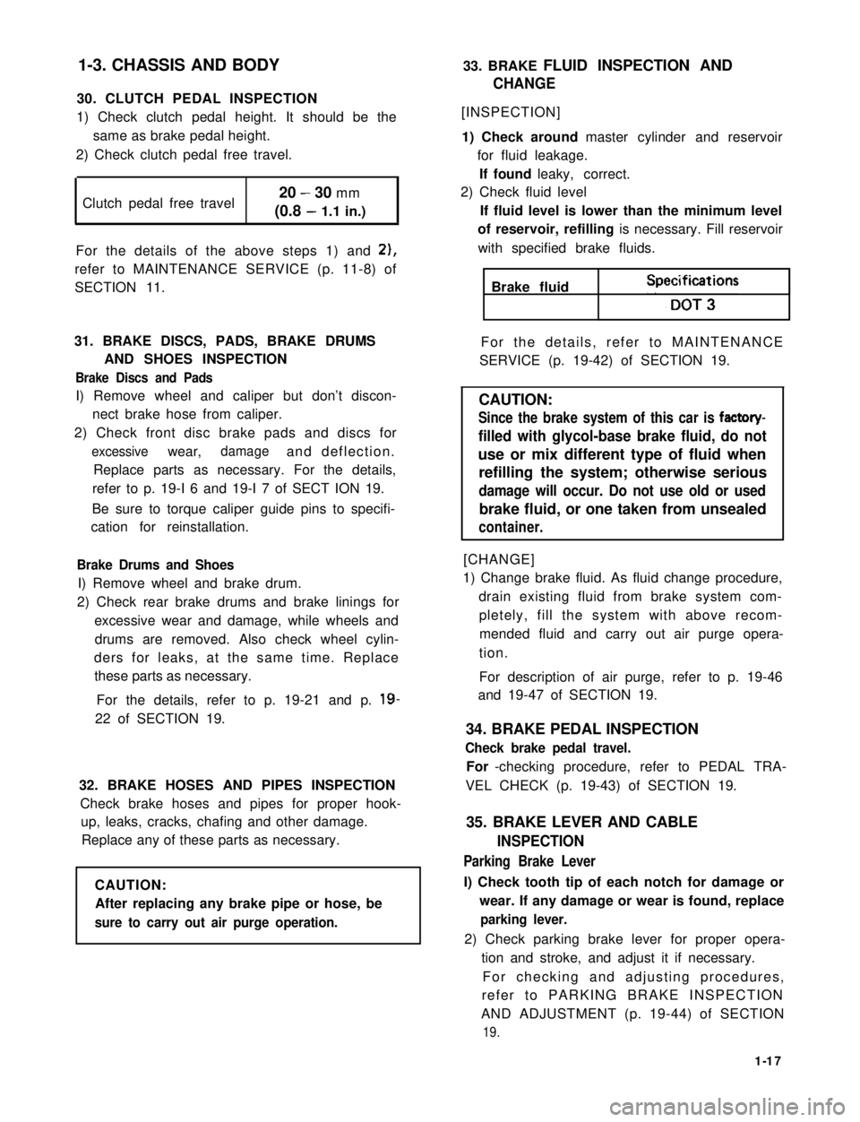
30. CLUTCH PEDAL INSPECTION
1) Check clutch pedal height. It should be the
same as brake pedal height.
2) Check clutch pedal free travel.
Clutch pedal free travel20 - 30 mm
(0.8 - 1.1 in.)
For the details of the above steps 1) and 2),
refer to MAINTENANCE SERVICE (p. 11-8) of
SECTION 11.
31. BRAKE DISCS, PADS, BRAKE DRUMS
AND SHOES INSPECTION
Brake Discs and Pads
I) Remove wheel and caliper but don’t discon-
nect brake hose from caliper.
2) Check front disc brake pads and discs for
excessivewear,damageand deflection.
Replace parts as necessary. For the details,
refer to p. 19-I 6 and 19-I 7 of SECT ION 19.
Be sure to torque caliper guide pins to specifi-
cation for reinstallation.
Brake Drums and Shoes
I) Remove wheel and brake drum.
2) Check rear brake drums and brake linings for
excessive wear and damage, while wheels and
drums are removed. Also check wheel cylin-
ders for leaks, at the same time. Replace
these parts as necessary.
For the details, refer to p. 19-21 and p. 19-
22 of SECTION 19.
32. BRAKE HOSES AND PIPES INSPECTION
Check brake hoses and pipes for proper hook-
up, leaks, cracks, chafing and other damage.
Replace any of these parts as necessary.
CAUTION:
After replacing any brake pipe or hose, be
sure to carry out air purge operation.
33. BRAKE FLUID INSPECTION AND
CHANGE
[INSPECTION]
1) Check around master cylinder and reservoir
for fluid leakage.
If found leaky, correct.
2) Check fluid level
If fluid level is lower than the minimum level
of reservoir, refilling is necessary. Fill reservoir
with specified brake fluids.
Brake fluid Speifi;t3ons
For the details, refer to MAINTENANCE
SERVICE (p. 19-42) of SECTION 19.
CAUTION:
Since the brake system of this car is factory-
filled with glycol-base brake fluid, do not
use or mix different type of fluid when
refilling the system; otherwise serious
damage will occur. Do not use old or used
brake fluid, or one taken from unsealed
container.
[CHANGE]
1) Change brake fluid. As fluid change procedure,
drain existing fluid from brake system com-
pletely, fill the system with above recom-
mended fluid and carry out air purge opera-
tion.
For description of air purge, refer to p. 19-46
and 19-47 of SECTION 19.
34. BRAKE PEDAL INSPECTION
Check brake pedal travel.
For -checking procedure, refer to PEDAL TRA-
VEL CHECK (p. 19-43) of SECTION 19.
35. BRAKE LEVER AND CABLE
INSPECTION
Parking Brake Lever
I) Check tooth tip of each notch for damage or
wear. If any damage or wear is found, replace
parking lever.
2) Check parking brake lever for proper opera-
tion and stroke, and adjust it if necessary.
For checking and adjusting procedures,
refer to PARKING BRAKE INSPECTION
AND ADJUSTMENT (p. 19-44) of SECTION
19.
1-17
Page 54 of 962
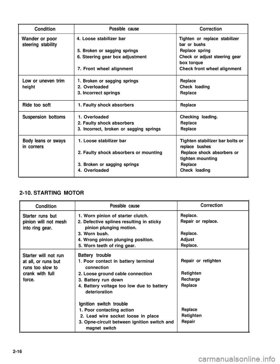
Condition
Wander or poor
steering stability
Low or uneven trim
height
Ride too soft
Suspension bottoms
Body leans or sways
in corners
Possible cause
4. Loose stabilizer bar
5. Broken or sagging springs
6. Steering gear box adjustment
7. Front wheel alignment
1. Broken or sagging springs
2. Overloaded
3. Incorrect springs
1. Faulty shock absorbers
1. Overloaded
2. Faulty shock absorbers
3. Incorrect, broken or sagging springs
1. Loose stabilizer bar
2. Faulty shock absorbers or mounting
3. Broken or sagging springs
4. Overloaded
Correction
Tighten or replace stabilizer
bar or bushs
Replace spring
Check or adjust steering gear
box torque
Check front wheel alignment
Replace
Check loading
Replace
Replace
Checking loading.
Replace
Replace
Tighten stabilizer bar bolts or
replace bushes
Replace shock absorbers or
tighten mounting
Replace
Check loading
STARTING MOTOR
Condition
Starter runs but
pinion will not mesh
into ring gear.
Starter will not run
at all, or runs but
runs too slow to
crank with full
force.
Possible cause
1. Worn pinion of starter clutch.
2. Defective splines resulting in sticky
pinion plunging motion.
3. Worn bush.
4. Wrong pinion plunging position.
5. Worn teeth of ring gear.
Battery trouble
1, Poor contact in battery terminal
connection
2. Loose ground cable connection
3. Battery run down
4. Battery voltage too low due to battery
deterioration
Correction
Replace.
Repair or replace.
Replace.
Adjust
Replace.
Repair or retighten
Retighten
Recharge
Replace
Ignition switch trouble
1. Poor contacting actionReplace
2. Lead wire socket loose in placeRetighten
3. Opne-circuit between ignition switch andRepair
magnet switch
2-10.
2-16
Page 80 of 962
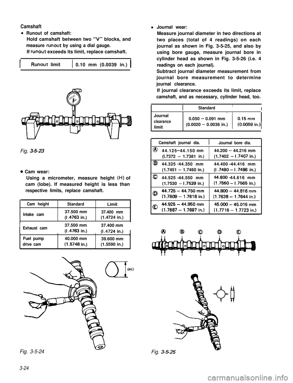
Camshaftl Journal wear:
l Runout of camshaft:
Hold camshaft between two “V” blocks, and
measure runout by using a dial gauge.
If runout exceeds its limit, replace camshaft.
Measure journal diameter in two directions at
two places (total of 4 readings) on each
journal as shown in Fig. 3-5-25, and also by
using bore gauge, measure journal bore in
cylinder head as shown in Fig. 3-5-26 (i.e. 4
readings on each journal).
Subtract journal diameter measurement from
journal bore measurement to determine
journal clearance.
If journal clearance exceeds its limit, replace
camshaft, and as necessary, cylinder head, too.
IRunout limit1 0.10 mm (0.0039 in.) 1
Fig. 3-5-23
0 Cam wear:
Using a micrometer, measure height (H) of
cam (lobe). If measured height is less than
respective limits, replace camshaft.
Cam heightStandardLimit
Intake cam37.500 mm37.400 mm
(I .4763 in.)(1.4724 in.),
IExhaust cam37.500 mm37.400 mm
(I .4763 in.)(I .4724 in.)IrFuel pump40.000 mm39.600 mm
drive cam(I .5748 in.)(1.5590 in.)
Fig. 3-5-24
3-24
IIStandard1I
Journal
clearance
limit
0.050 - 0.091 mm
(0.0020 - 0.0036 in.)
Camshaft journal dia.Journal bore dia.
@44.125 44.150-mm44.200 - 44.216 mm
(I.7372 - 1.7381in.)(1.7402 - I .7407 in.)
@44.325 44.350 mm- 44.400 44.416 mm
(1.7451 - 1.7460 in.)(I .7480 - I .7486 in.)
044.525 44.550 mm-44~600 44.616 mm-
(1.7530 - I .7539 in.)(I .7560 - I .7565 in.)
Fig. 3-5-25
Page 82 of 962
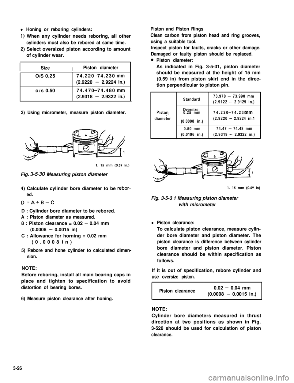
l Honing or reboring cylinders:
1) When any cylinder needs reboring, all other
cylinders must also be rebored at same time.
2) Select oversized piston according to amount
of cylinder wear.
ISizeIPiston diameter
O/S0.2574.220 74.230-mm
(2.9220 - 2.9224in.)
74.470 74.480-o/s0.50mm
(2.9318 - 2.9322in.)
3) Using micrometer, measure piston diameter.
1. 15 mm (0.59 in.)
Fig. 3-5-30 Measuring piston diameter
4) Calculate cylinder bore diameter to be rebor-
ed.
D=A+B-C
D : Cylinder bore diameter to be rebored.
A : Piston diameter as measured.
8 : Piston clearance = 0.02 - 0.04 mm
(0.0008 - 0.0015 in)
C : Allowance for horning = 0.02 mm
(0.0008 in)
5) Rebore and hone cylinder to calculated dimen-
sion.
NOTE:
Before reboring, install all main bearing caps in
place and tighten to specification to avoid
distortion of bearing bores.
6) Measure piston clearance after honing.
Piston and Piston Rings
Clean carbon from piston head and ring grooves,
using a suitable tool.
Inspect piston for faults, cracks or other damage.
Damaged or faulty piston should be replaced.
0Piston diameter:
As indicated in Fig. 3-5-31, piston diameter
should be measured at the height of 15 mm
(0.59 in) from piston skirt end in the direc-
tion perpendicular to piston pin.
Standard73.970 - 73.990 mm
(2.9122 - 2.9129 in.)
Piston
diameter
Oversize:0.25 mm
(0.0098 in.)
0.50 mm
(0.0196 in.)
74.220 74.230- mm
(2.9220 - 2.9224 in.1
74.47 - 74.48 mm
(2.9319 - 2.9322 in.)
1. 15 mm (0.59 in)
Fig. 3-5-3 1 Measuring piston diameter
with micrometer
l Piston clearance:
To calculate piston clearance, measure cylin-
der bore diameter and piston diameter. The
piston clearance is difference between cylinder
bore diameter and piston diameter. Piston
clearance should be within specification as
follows.
If it is out of specification, rebore cylinder and
use oversize piston.
Piston clearance0.02 - 0.04 mm
(0.0008 - 0.0015 in.)
NOTE:
Cylinder bore diameters measured in thrust
direction at two positions as shown in Fig.
3-528 should be used for calculation of piston
clearance.
3-26
Page 135 of 962
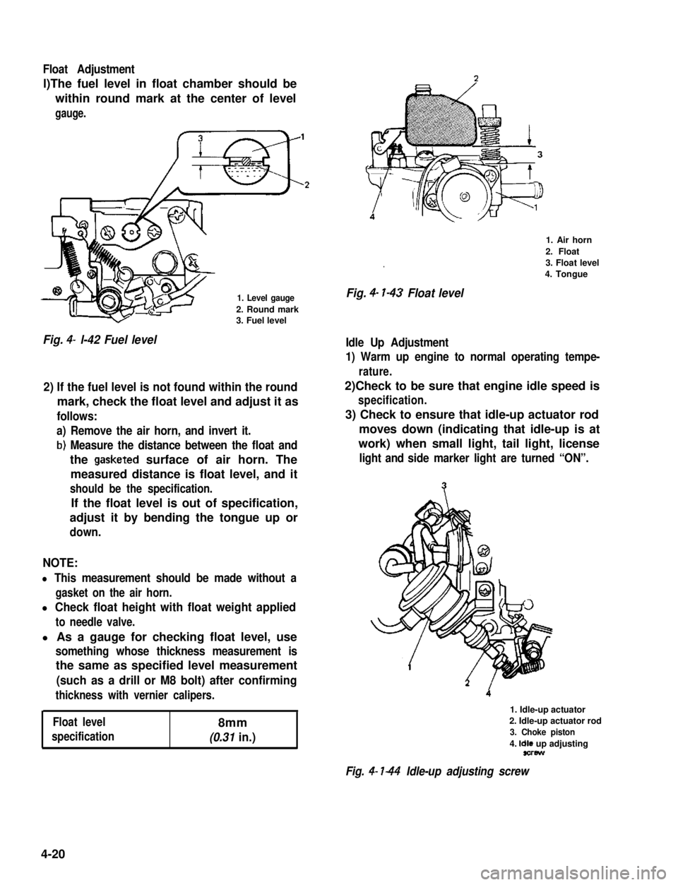
Float Adjustment
l)The fuel level in float chamber should be
within round mark at the center of level
gauge.
1. Level gauge
2. Round mark3. Fuel level
Fig. 4- l-42 Fuel level
2) If the fuel level is not found within the round
mark, check the float level and adjust it as
follows:
a) Remove the air horn, and invert it.
b) Measure the distance between the float and
the gasketed surface of air horn. The
measured distance is float level, and it
should be the specification.
If the float level is out of specification,
adjust it by bending the tongue up or
down.
NOTE:
l This measurement should be made without a
gasket on the air horn.
l Check float height with float weight applied
to needle valve.
l As a gauge for checking float level, use
something whose thickness measurement is
the same as specified level measurement
(such as a drill or M8 bolt) after confirming
thickness with vernier calipers.
Float level8mm
specification(0.31 in.)
.
Fig. 4- l-43 Float level
1. Air horn
2. Float
3. Float level
4. Tongue
Idle Up Adjustment
1) Warm up engine to normal operating tempe-
rature.
2)Check to be sure that engine idle speed is
specification.
3) Check to ensure that idle-up actuator rod
moves down (indicating that idle-up is at
work) when small light, tail light, license
light and side marker light are turned “ON”.
1. Idle-up actuator
2. Idle-up actuator rod
3. Choke piston
4. Idle up adjustingsorew
Fig. 4- l-44 Idle-up adjusting screw
4-20
Page 253 of 962
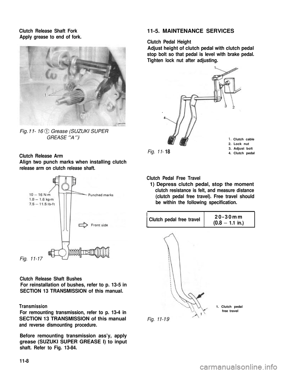
Clutch Release Shaft Fork
Apply grease to end of fork.
Fig. I l- 16 @ Grease (SUZUKI SUPER
GREASE “‘A “)
Clutch Release Arm
Align two punch marks when installing clutch
release arm on clutch release shaft.
Fig. 11-17
Clutch Release Shaft Bushes
For reinstallation of bushes, refer to p. 13-5 in
SECTION 13 TRANSMISSION of this manual.
Transmission
For remounting transmission, refer to p. 13-4 in
SECTION 13 TRANSMISSION of this manual
and reverse dismounting procedure.
11-5. MAINTENANCE SERVICES
Clutch Pedal Height
Adjust height of clutch pedal with clutch pedal
stop bolt so that pedal is level with brake pedal.
Tighten lock nut after adjusting.
.
4
I-
I- 18
1. Clutch cable2. Lock nut3. Adjust bolt4. Clutch pedalFig. 1
Clutch Pedal Free Travel
1) Depress clutch pedal, stop the moment
clutch resistance is felt, and measure distance
(clutch pedal free travel). Free travel should
be within the following specification.
!Clutch pedal free travel20-30mm
(0.8 - 1.1 in.)c
Fig. 1
1. Clutch pedalfree travel
Before remounting transmission ass’y, apply
grease (SUZUKI SUPER GREASE I) to input
shaft. Refer to Fig. 13-84.
11-8
Page 414 of 962
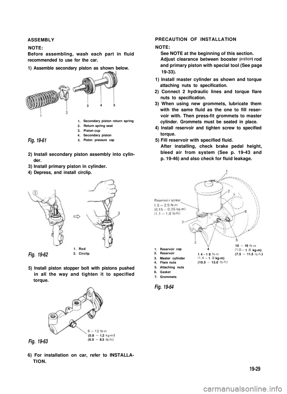
ASSEMBLYPRECAUTION OF INSTALLATION
NOTE:NOTE:
Before assembling, wash each part in fluidSee NOTE at the beginning of this section.
recommended to use for the car.Adjust clearance between booster piston rod
1) Assemble secondary piston as shown below.
FBh
and primary piston with special tool (See page
19-33).
Fig. 19-61
1) Install master cylinder as shown and torque
attaching nuts to specification.
2) Connect 2 hydraulic lines and torque flare
1.
2.
3.
4.
5.
I I345
Secondary piston return spring
Return spring seat
Piston cupSecondary piston
Piston pressure cap
2) Install secondary piston assembly into cylin-
der.
3) Install primary piston in cylinder.
4) Depress, and install circlip.
nuts to specification.
3) When using new grommets, lubricate them
with the same fluid as the one to fill reser-
voir with. Then press-fit grommets to master
cylinder. Grommets must be seated in place.
4) Install reservoir and tighten screw to specified
torque.
5) Fill reservoir with specified fluid.
After installing, check brake pedal height,
bleed air from system (See p. 19-43 and
p. 19-46) and also check for fluid leakage.
:
Fig. 19-622. Circlip
1. Rod
5) Install piston stopper bolt with pistons pushed
in all the way and tighten it to specified
torque.
(0.8 - 1.2 kam)
1.Reservoir10 - 16 N.mcap42.Reservoir(1 .O - 1 .6 kg-m)14-18N.m(7.5 - 11.5 lb-ftl--I3.Master cylinder(1 .4 - 1.8 kg-m)4.Flare nuts(10.5 -13.0 lb-ft)
5.Attaching nuts
6.Gasket
7.Grommets
Fig. 19-64
Fig. 19-63(6.0 - 8.5 lb-ft).
6) For installation on car, refer to INSTALLA-
TION.
19-29
Page 422 of 962
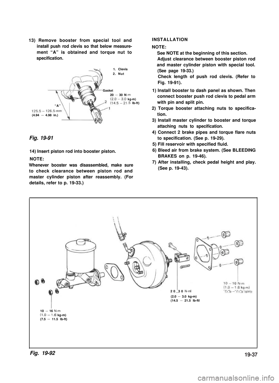
13) Remove booster from special tool and
install push rod clevis so that below measure-
ment “A” is obtained and torque nut to
specification.
-41. Clevis
2. Nut
Gasket20 - 30 N
“A”
125.5- 126.5mm(4.94 - 4.98 in.)\
.rnkg-m).5 lb-ft)
Fig. 19-91
14) Insert piston rod into booster piston.
NOTE:
Whenever booster was disassembled, make sure
to check clearance between piston rod and
INSTALLATION
NOTE:
See NOTE at the beginning of this section.
Adjust clearance between booster piston rod
and master cylinder piston with special tool.
(See page 19-33.)
Check length of push rod clevis. (Refer to
Fig. 19-91).
1) Install booster to dash panel as shown. Then
connect booster push rod clevis to pedal arm
with pin and split pin.
2) Torque booster attaching nuts to specifica-
tion.
3) Install master cylinder to booster and torque
attaching nuts to specification.
4) Connect 2 brake pipes and torque flare nuts
to specification. (See p. 19-29).
5) Fill reservoir with specified fluid.
6) Bleed air from brake system. (See BLEEDING
BRAKES on p. 19-46).
7) After installing, check pedal height and play.
(See p. 19-43).
master cylinder piston after reassembly. (For
details, refer to p. 19-33.)
20 30 N.m-(2.0 - 3.0 kg-m)(14.5 - 21.5 lb-ftl
10 - 16 N.m(1.0-1.6 kg-m)(7.5 - 11.5 lb-ft)
Fig. 19-9219-37