Page 428 of 962

BRAKE PEDAL FREE HEIGHT ADJUSTMENT
Brake pedal height is normal if brake pedal is
as high as clutch pedal.
1) When booster push rod clevis has been
reinstalled, it is important that measurement
between booster mounting surface (with a
gasket attached) and the center of clevis
pin hole is adjusted within 125.5 mm -
126.5 mm (4.94 - 4.98 in.). (See page
19-37.)
2) When stop light switch has been removed,
refer to the following STOP LIGHT SWITCH
ADJUSTMENT for proper installation.
The services in above steps 1) and 2) may
affect brake pedal height.
STOP LIGHT SWITCH ADJUSTMENT
Adjustment should be made as follows when
installing the switch.
Pull up brake pedal toward you and while
holding it there, adjust switch position so that
clearance between the end of thread and brake
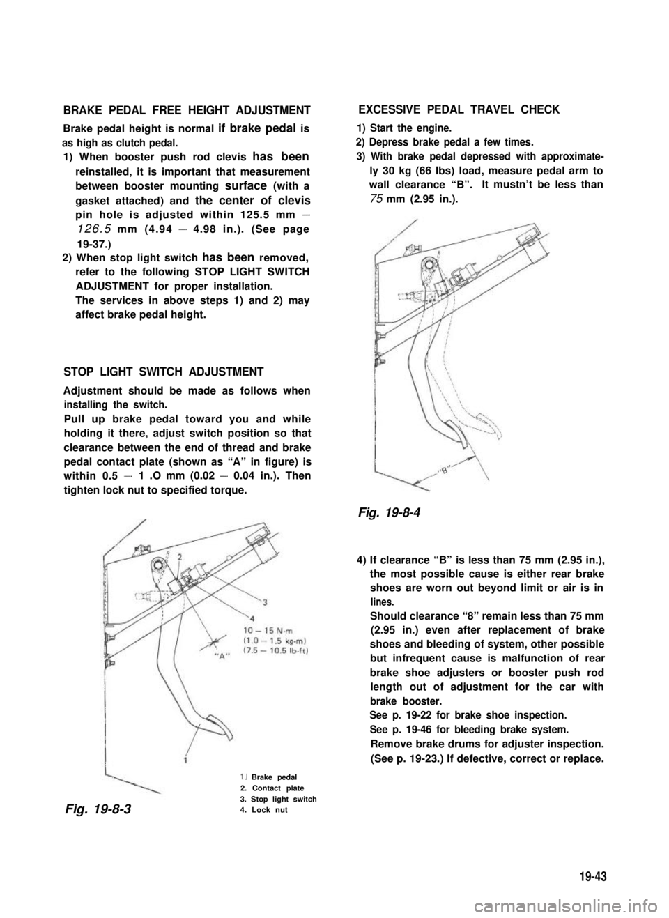
pedal contact plate (shown as “A” in figure) is
within 0.5 -1 .O mm (0.02 - 0.04 in.). Then
tighten lock nut to specified torque.
1. Brake pedal
2. Contact plate
3. Stop light switch4. Lock nut
EXCESSIVE PEDAL TRAVEL CHECK
1) Start the engine.
2) Depress brake pedal a few times.
3) With brake pedal depressed with approximate-
ly 30 kg (66 Ibs) load, measure pedal arm to
wall clearance “B”.It mustn’t be less than
75 mm (2.95 in.).
Fig. 19-8-4
4) If clearance “B” is less than 75 mm (2.95 in.),
the most possible cause is either rear brake
shoes are worn out beyond limit or air is in
lines.
Should clearance “8” remain less than 75 mm
(2.95 in.) even after replacement of brake
shoes and bleeding of system, other possible
but infrequent cause is malfunction of rear
brake shoe adjusters or booster push rod
length out of adjustment for the car with
brake booster.
See p. 19-22 for brake shoe inspection.
See p. 19-46 for bleeding brake system.
Remove brake drums for adjuster inspection.
(See p. 19-23.) If defective, correct or replace.
Fig. 19-8-3
19-43
Page 433 of 962
4) If pedal travel doesn’t change, air tightness
isn’t obtained.
\1 St, 2nd. 3rd
NO GOOD
Fig. 19-8-17
NOTE:
If defective, inspect vacuum lines and sealing
parts, and replace any faulty part.
When this has been done, repeat the entire test!
Check Operation
1) With engine stopped, depress brake pedal
several times with the same load and make
sure that pedal travel doesn’t change.
Fig. 19-8-19 \
Check Air Tightness Under Load
1) With engine running, depress brake pedal.
Then stop engine while holding brake pedal
depressed.
-Hold
Fig. 19-8-20
2) Hold brake pedal depressed for 30 seconds.
If pedal height does n.ot change, condition
is good. But it isn’t if pedal rises.
Fig. 19-8-18
2) Start engine while depressing brake pedal. If
pedal travel increases a little, operation is
satisfactory. But no change in pedal travel
indicates malfunction.
Fig. 19-8-21Hold
19-48
Page 473 of 962

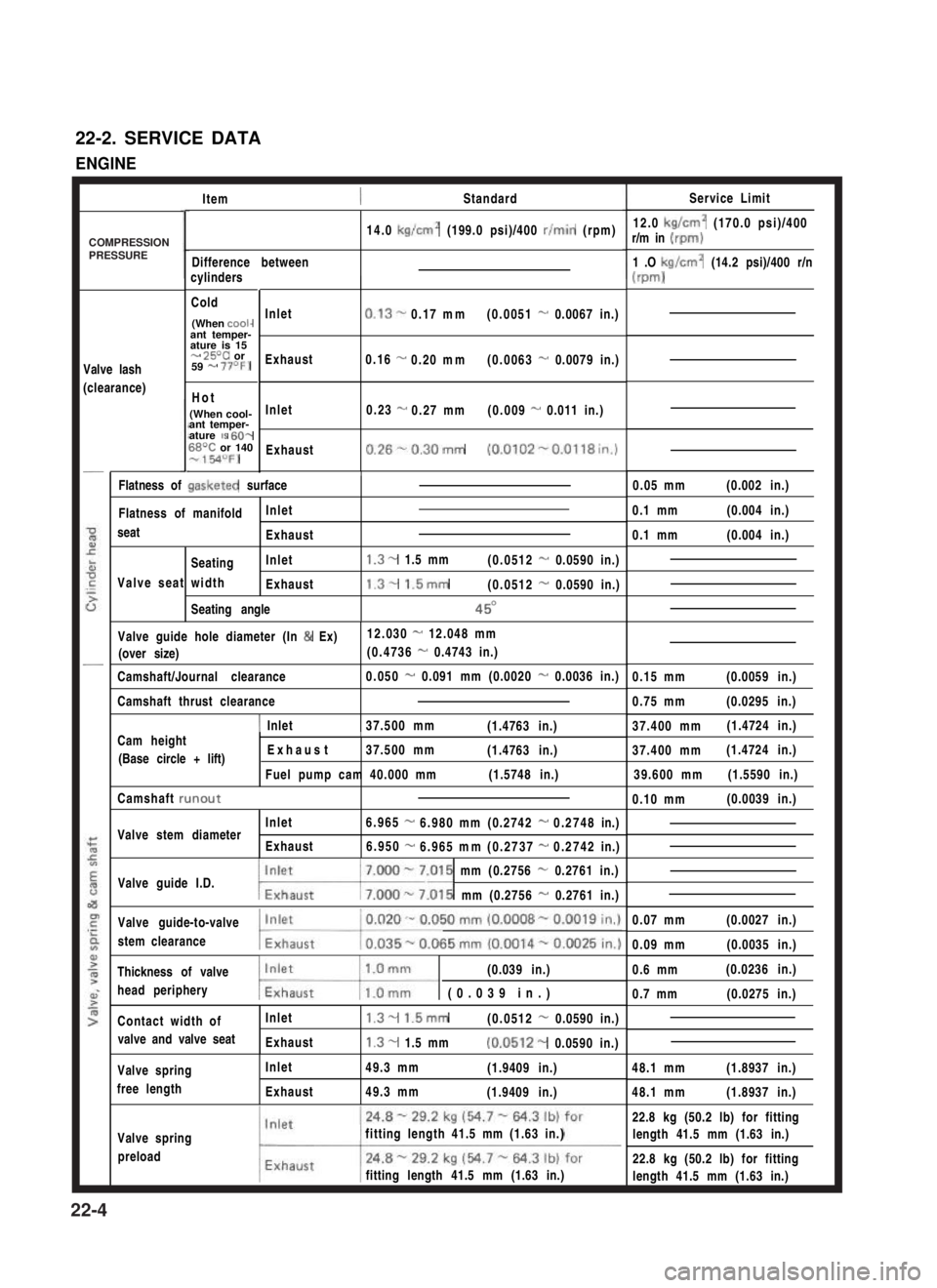
22-2. SERVICE DATA
ENGINE
ItemStandardService Limit
12.0 kg/cm2 (170.0 psi)/400r/m in (rpm)
1 .O kg/cm2 (14.2 psi)/400 r/n
(m-d
14.0 kg/cm2 (199.0 psi)/400 r/min (rpm)
Difference betweencylinders
Cold
(When cooi-ant temper-ature is 15- 25T or59 - 77OF)
Hot
(When cool-ant temper-ature IS 60-68T or 140-154OFJ
Valve lash
(clearance)
Inlet
Exhaust
Inlet
Exhaust
0.13-0.17mm(0.0051 - 0.0067 in.)
0.16 -0.20mm(0.0063 - 0.0079 in.)
0.23 -0.27mm(0.009 - 0.011 in.)
0.26%0.30mm (0.0102-0.0118in.)
/0.05 mm(0.002 in.)Flatness of gasketed surface
Flatness of manifoldInlet
seatExhaust
SeatingInlet
Valve seat widthExhaust
Seating angle
1.3- 1.5 mm(0.0512 - 0.0590 in.)
1.3- 1.5mm(0.0512 - 0.0590 in.)
45O
0.1 mm(0.004 in.)
0.1 mm(0.004 in.)
Valve guide hole diameter (In & Ex)12.030 - 12.048 mm
(over size)(0.4736 - 0.4743 in.)
Camshaft/Journal clearance0.050 - 0.091 mm (0.0020 - 0.0036 in.)0.15 mm(0.0059 in.)
0.75 mm(0.0295 in.)Camshaft thrust clearance
1 Inlet37.500 mm(1.4763 in.)37.400 mm(1.4724 in.)Cam heightI
(Base circle + lift) Exhaust37.500 mm(1.4763 in.)
Fuel pump cam 40.000 mm(1.5748 in.)
37.400 mm(1.4724 in.)
39.600 mm(1.5590 in.)
Camshaft runout0.10 mm(0.0039 in.)
Inlet6.965-6.980mm(0.2742-0.2748in.)Valve stem diameterExhaust6.950-6.965mm(0.2737-0.2742in.)
Valve guide I.D.7.000 - 7.015 mm (0.2756 - 0.2761 in.)
w.015 mm (0.2756 - 0.2761 in.)
Valve guide-to-valve
stem clearance
0.07 mm(0.0027 in.)
0.09 mm(0.0035 in.)
Thickness of valve(0.039 in.)
head peripherymw (0.039 in.)
0.6 mm(0.0236 in.)
0.7 mm(0.0275 in.)
Contact width ofInlet1.3- 1.5mm(0.0512 - 0.0590 in.)
valve and valve seatExhaust1.3- 1.5 mm(0.0512- 0.0590 in.)
48.1 mm(1.8937 in.)Valve spring
free length
Inlet
Exhaust
49.3 mm(1.9409 in.)
49.3 mm(1.9409 in.)48.1 mm(1.8937 in.)
Valve spring
preload
fitting length 41.5 mm (1.63 in.)
fitting length 41.5 mm (1.63 in.)
22.8 kg (50.2 lb) for fitting
length 41.5 mm (1.63 in.)
22.8 kg (50.2 lb) for fitting
length 41.5 mm (1.63 in.)
COMPRESSIONPRESSURE
22-4