Page 157 of 962

THERMOSTATICALLY CONTROLLED AIR CLEANER (TCAC) SYSTEM
This system helps to improve fuel vaporization by controlling the temperature of the intake air almost at
a constant level automatically regardless of driving conditions and outside temperature, to distribute the
mixture to each cylinder evenly and to stabilize the air/fuel mixture ratio.
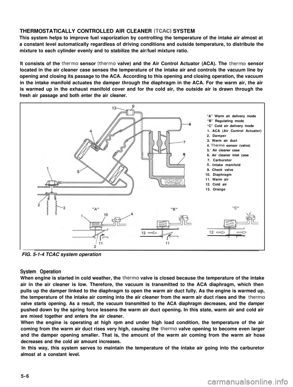
It consists of the therm0 sensor (therm0 valve) and the Air Control Actuator (ACA). The therm0 sensor
located in the air cleaner case senses the temperature of the intake air and controls the vacuum line by
opening and closing its passage to the ACA. According to this opening and closing operation, the vacuum
in the intake manifold actuates the damper through the diaphragm in the ACA. For the warm air, the air
is warmed up in the exhaust manifold cover and for the cold air, the outside air is drawn through the
fresh air passage and both enter the air cleaner.
“A” Warm air delivery mode
6“B” Regulating mode
“C” Cold air delivery mode
1. ACA (Air Control Actuator)
2. Damper3. Warm air duct
4. Therm0 sensor (valve)5.’ Air cleaner case66. Air cleaner inlet case
7. Carburetor8. Intake manifold9. Check valve10. Diaphragm11. Warm air
12. Cold air
13. Orange
--
System Operation
When engine is started in cold weather, the therm0 valve is closed because the temperature of the intake
air in the air cleaner is low. Therefore, the vacuum is transmitted to the ACA diaphragm, which then
pulls up the damper linked to the diaphragm to open the warm air duct fully. As the engine is warmed up,
the temperature of the intake air coming into the air cleaner from the warm air duct rises and the therm0
valve starts opening. As a result, the vacuum transmitted to the ACA diaphragm decreases, and the damper
pushed down by the spring force lessens the warm air duct opening. In this state, warm air and cold air
are mixed together and enters the air cleaner.
When the engine is operating at high rpm and under high load condition, the temperature of the air
coming from the warm air duct rises very high, causing the therm0 valve opening to become even larger
and the damper opening smaller. That is, the amount of the warm air coming from the warm air hose
decreases and the cold air amount increases.
In this way, this system serves to maintain the temperature of the intake air going into the carburetor
almost at a constant level.
5-6
FIG. 5-1-4 TCAC system operation
Page 243 of 962

3) Make sure to assemble stator terminal
insulator properly.
10-2. BATTERY
1. Stator terminal insulator
Fig. lo-20
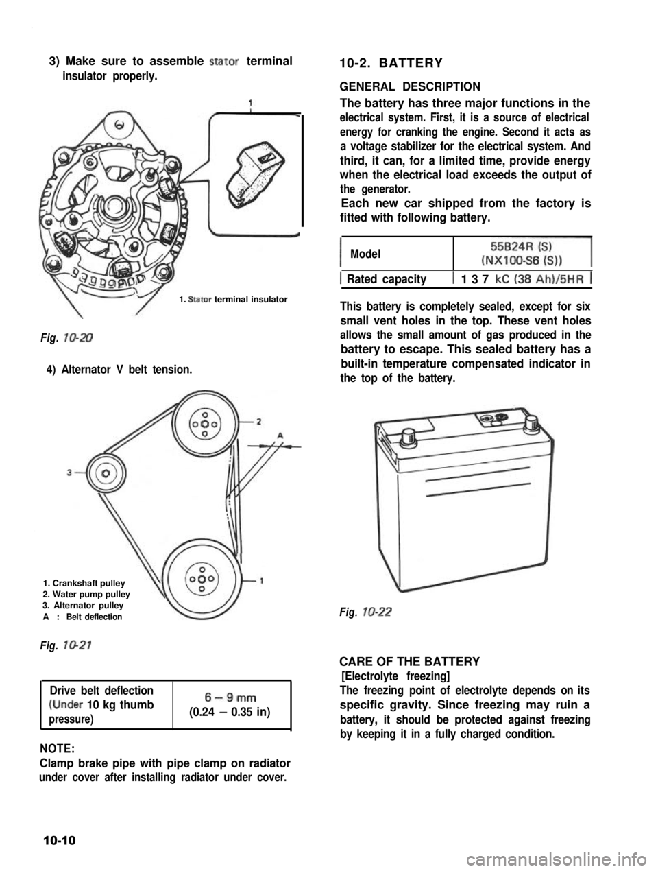
4) Alternator V belt tension.
1. Crankshaft pulley
2. Water pump pulley
3. Alternator pulley
A :Belt deflection
Fig. 1021
Drive belt deflection
(Under 10 kg thumb
pressure)
6-9mm
(0.24 - 0.35 in)
NOTE:
Clamp brake pipe with pipe clamp on radiator
under cover after installing radiator under cover.
GENERAL DESCRIPTION
The battery has three major functions in the
electrical system. First, it is a source of electrical
energy for cranking the engine. Second it acts as
a voltage stabilizer for the electrical system. And
third, it can, for a limited time, provide energy
when the electrical load exceeds the output of
the generator.
Each new car shipped from the factory is
fitted with following battery.
IModel55BzR=l(NXIOO-S6 6))
1 Rated capacityt 137 kC (38 Ah)/5HR j
This battery is completely sealed, except for six
small vent holes in the top. These vent holes
allows the small amount of gas produced in the
battery to escape. This sealed battery has a
built-in temperature compensated indicator in
the top of the battery.
Fig. lo-22
CARE OF THE BATTERY
[Electrolyte freezing]
The freezing point of electrolyte depends on its
specific gravity. Since freezing may ruin a
battery, it should be protected against freezing
by keeping it in a fully charged condition.
10-10
Page 392 of 962
![SUZUKI GRAND VITARA 1987 Service Repair Manual [Caliper OPERATION]
Single piston floating caliper type
The single piston floating caliper type brake is
employed in this model. One cylinder and one
piston are used for this type. (The cylinder is
co SUZUKI GRAND VITARA 1987 Service Repair Manual [Caliper OPERATION]
Single piston floating caliper type
The single piston floating caliper type brake is
employed in this model. One cylinder and one
piston are used for this type. (The cylinder is
co](/manual-img/20/57437/w960_57437-391.png)
[Caliper OPERATION]
Single piston floating caliper type
The single piston floating caliper type brake is
employed in this model. One cylinder and one
piston are used for this type. (The cylinder is
constructed as a monoblock with the caliper.)
Fluid pressure generated in the cylinder causes
the pad (1) on the piston side to press against
the disc. At the same time, the floating type
caliper body is moved to the right by the cylin-
der pressure, as shown in below figure, which
pulls pad (2) against the disc and so brakes the
wheel.
Caliper body
\Brake disc (rotor)
Fig. 19-6 - ’
The disc brake has no servo assistance as in drum
braking, and it is necessary to increase the work-
ing pressure of the piston and pad. For this pur-
pose, the wheel cylinder has a large bore. Even
only a little change in clearance between the disc
and pad has therefore a large influence on the
brake pedal stroke. It is necessary to have the
clearance adjusted to the minimum at all times,
by means of the piston (rubber) seal.
Piston seal (Rubber seal)Piston sealWinder (Rubber seal)
II
IPiston
Hydraulic pressure
“OFF“
Fig. 19-7
Clearance correction
Piston
Hydraulic pressure
“ON”
When oil pressure is applied to the piston, the
piston moves forward. The rubber seal, which
exerts considerable pressure against the piston,
moves with the cylinder. However, as a part of
the rubber seal has been fixed into a groove in
the cylinder, the shape of the rubber seal is dis-
torted toward internal end of the cylinder, as
shown in above figure. When pressure is taken
off from the foot brake pedal and fluid pressure
is released from the piston, a restoring force is
generated at the seal and pushes the piston back.
As the pads wear away and the clearance be-
tween the disc and pads becomes larger, the
piston moves a larger distance. The seal then
could change in shape further but, since the end
of the seal is fixed into the groove in the cylin-
der, the distortion is limited to the same amount
as previously described. The piston moves
further to cover the distance of clearance. The
piston returns by the same distance and the
rubber seal recovers its shape as described
above and thus the clearance between the disc
and pads are maintained in adjustment.
19-7
Cylinder