1987 SUZUKI GRAND VITARA horn
[x] Cancel search: hornPage 49 of 962

Condition
Excessive gear noise
Hard shifting
2-6. DIFFERENTIALS
Possible cause
1. Not enough oil in transmission
2. Defective synchronizer
3. Gears rattling in thrust direction
4. Broken or worn bearings
5. Damaged or worn gears
1. Clutch pedal play too large, resulting in a
“dragging clutch”
2. Worn clutch disc facings
3. Clutch disc facings dirty with oil.
4. Distorted or unevenly worn shift fork shaft
5. Broken locating balls
6. Worn synchornizer sleeve or ring
7. Worn synchronizer hub
Condition
Gear noise
Bearing noise
Possible cause
1. Maladjusted backlash between drive pinion
and ring gear
2. Damaged gear teeth or improper mesh of
drive pinion and ring gear
3. Improper tooth contact in the mesh between
drive pinion and ring gear
4. Insufficient or wrong kind of gear oil
5. Ring gear wobbling when turning, or ring
gear securing bolts loose
6. Broken or otherwise damaged teeth of side
gears or differential pinion gears
1. (Constant noise) Insufficient or wrong kind
of gear oil
2. (Constant noise) Damaged or worn bearings
or borne parts
3. (Noise during coasting) Damaged bearings
of rear drive pinion
4. (Noise during turning) Broken bearings
on axle shafts
Correction
Replenish
Replace
Replace
Replace
Replace
Adjust as prescribed
Replace.
Replace.
Replace
Replace
Replace
Replace
Correction
Adjust as prescribed
Replace or adjust
Adjust as prescribed
Replenish or replace
Replace, or retighten
Replace
Replenish or change
Replace.
Replace
Replace
2-11
Page 82 of 962
l Honing or reboring cylinders:
1) When any cylinder needs reboring, all other
cylinders must also be rebored at same time.
2) Select oversized piston according to amount
of cylinder wear.
ISizeIPiston diameter
O/S0.2574.220 74.230-mm
(2.9220 - 2.9224in.)
74.470 74.480-o/s0.50mm
(2.9318 - 2.9322in.)
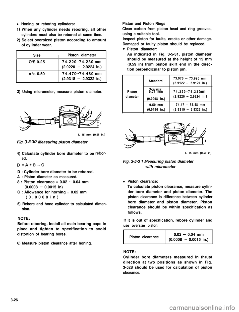
3) Using micrometer, measure piston diameter.
1. 15 mm (0.59 in.)
Fig. 3-5-30 Measuring piston diameter
4) Calculate cylinder bore diameter to be rebor-
ed.
D=A+B-C
D : Cylinder bore diameter to be rebored.
A : Piston diameter as measured.
8 : Piston clearance = 0.02 - 0.04 mm
(0.0008 - 0.0015 in)
C : Allowance for horning = 0.02 mm
(0.0008 in)
5) Rebore and hone cylinder to calculated dimen-
sion.
NOTE:
Before reboring, install all main bearing caps in
place and tighten to specification to avoid
distortion of bearing bores.
6) Measure piston clearance after honing.
Piston and Piston Rings
Clean carbon from piston head and ring grooves,
using a suitable tool.
Inspect piston for faults, cracks or other damage.
Damaged or faulty piston should be replaced.
0Piston diameter:
As indicated in Fig. 3-5-31, piston diameter
should be measured at the height of 15 mm
(0.59 in) from piston skirt end in the direc-
tion perpendicular to piston pin.
Standard73.970 - 73.990 mm
(2.9122 - 2.9129 in.)
Piston
diameter
Oversize:0.25 mm
(0.0098 in.)
0.50 mm
(0.0196 in.)
74.220 74.230- mm
(2.9220 - 2.9224 in.1
74.47 - 74.48 mm
(2.9319 - 2.9322 in.)
1. 15 mm (0.59 in)
Fig. 3-5-3 1 Measuring piston diameter
with micrometer
l Piston clearance:
To calculate piston clearance, measure cylin-
der bore diameter and piston diameter. The
piston clearance is difference between cylinder
bore diameter and piston diameter. Piston
clearance should be within specification as
follows.
If it is out of specification, rebore cylinder and
use oversize piston.
Piston clearance0.02 - 0.04 mm
(0.0008 - 0.0015 in.)
NOTE:
Cylinder bore diameters measured in thrust
direction at two positions as shown in Fig.
3-528 should be used for calculation of piston
clearance.
3-26
Page 117 of 962
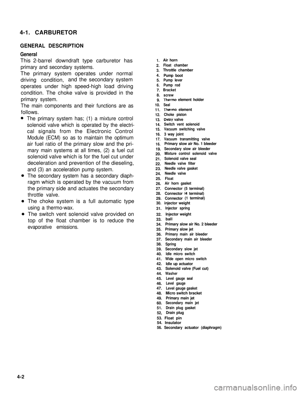
4-1. CARBURETOR
GENERAL DESCRIPTION
General
This 2-barrel downdraft type carburetor has
primary and secondary systems.
The primary system operates under normal
driving condition,and the secondary system
operates under high speed-high load driving
condition. The choke valve is provided in the
primary system.
The main components and their functions are as
follows.
The primary system has; (1) a mixture control
solenoid valve which is operated by the electri-
cal signals from the Electronic Control
Module (ECM) so as to maintain the optimum
air fuel ratio of the primary slow and the pri-
mary main systems at all times, (2) a fuel cut
solenoid valve which is for the fuel cut under
deceleration and prevention of the dieseling,
and (3) an acceleration pump system.
The secondary system has a secondary diaph-
ragm which is operated by the vacuum from
the primary side and actuates the secondary
throttle valve.
The choke system is a full automatic type
using a thermo-wax.
The switch vent solenoid valve provided on
top of the float chamber is to reduce the
evaporative emissions.
1.Air horn
2.Float chamber
3.Throttle chamber
4.Pump boot5.Pump lever
6.Pump rod
7.Bracket
8.screw
9.Therm0 element holder
10.Seal
11.Therm0 element
12.Choke piston
13.Delay valve
14.Switch vent solenoid
15.Vacuum switching valve
16.3 way joint
17.Vacuum transmitting valve
16.Primary slow air No. 1 bleeder
19.Secondary slow air bleeder
20.Mixture control solenoid valve
21.Solenoid valve seal
22.Needle valve filter
23.Needle valve gasket
24.Needle valve
25.Float
26.Air horn gasket
27.Connector (5 terminal)
28.Connector (4 terminal)
29.Connector (1 terminal)
30. injector weight
31.Injector spring
32.Injector weight
33.
34.Primary slow air No. 2 bleeder
35.Primary slow jet
36.Primary main air bleeder
37.Secondary main air bleeder
38.Spring
39.Secondary slow jet
40.Idle micro switch
41.Wide open micro switch
42.Idle up actuator43.Solenoid valve (Fuel cut)
44.Washer
45.Level gauge seal
46.Level gauge
47.Level gauge gasket
48.Micro switch bracket
49.Primary main jet
60.Secondary main jet
51.Drain plug gasket
52,Drain plug
53. Float pin54. Insulator56. Secondary actuator (diaphragm)
4-2
ball
Page 129 of 962
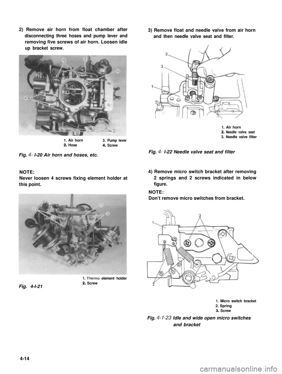
2) Remove air horn from float chamber after
disconnecting three hoses and pump lever and
removing five screws of air horn. Loosen idle
up bracket screw.
3) Remove float and needle valve from air horn
and then needle valve seat and filter.
1. Air horn
2. Needle valve seat
3. Needle valve filter1. Air horn3. Pump lever2. Hose4. Screw
Fig. 4- l-22 Needle valve seat and filterFig. 4- l-20 Air horn and hoses, etc.
NOTE:
Never loosen 4 screws fixing element holder at
this point.
4) Remove micro switch bracket after removing
2 springs and 2 screws indicated in below
figure.
NOTE:
Don’t remove micro switches from bracket.
1. Therm0 element holder
2. ScrewFig. 4-l-21
1. Micro switch bracket
2. Spring
3. Screw
Fig. 4- l-23 Idle and wide open micro switches
and bracket
4-14
Page 133 of 962
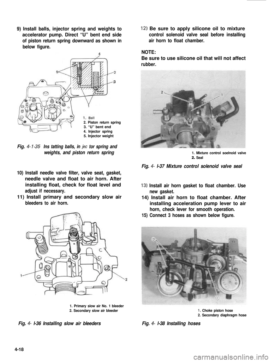
9) Install balls, injector spring and weights to
accelerator pump. Direct “U” bent end side
of piston return spring downward as shown in
below figure.
3
2. Piston return spring3. “U” bent end4. Injector spring5. Injector weight
Fig. 4- l-35Ins tatting balls, in jet tor spring and
weights, and piston return spring
10) Install needle valve filter, valve seat, gasket,
needle valve and float to air horn. After
installing float, check for float level and
adjust if necessary.
11) Install primary and secondary slow air
bleeders to air horn.
1. Primary slow air No. 1 bleeder
2. Secondary slow air bleeder
Fig. 4- l-36 Installing slow air bleeders
12) Be sure to apply silicone oil to mixture
control solenoid valve seal before installing
air horn to float chamber.
NOTE:
Be sure to use silicone oil that will not affect
rubber.
1. Mixture control soelnoid valve
2. Seal
Fig. 4- l-37 Mixture control solenoid valve seal
13) Install air horn gasket to float chamber. Use
new gasket.
14) Install air horn to float chamber. After
installing acceleration pump lever to air
horn, check lever for smooth operation.
15) Connect 3 hoses as shown below figure.
I, Choke piston hose
2. Secondary diaphragm hose
Fig. 4- l-38 Installing hoses
4-18
Page 135 of 962
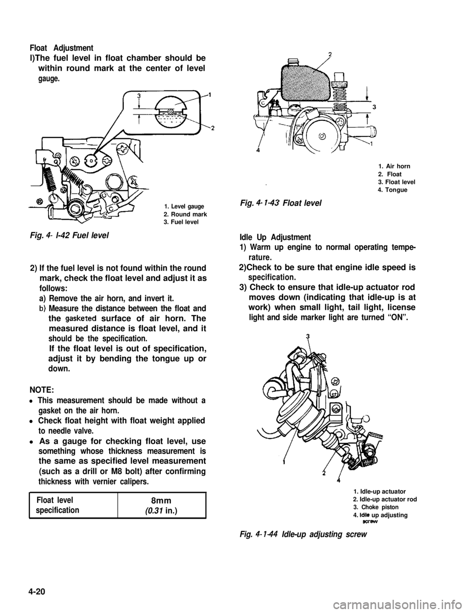
Float Adjustment
l)The fuel level in float chamber should be
within round mark at the center of level
gauge.
1. Level gauge
2. Round mark3. Fuel level
Fig. 4- l-42 Fuel level
2) If the fuel level is not found within the round
mark, check the float level and adjust it as
follows:
a) Remove the air horn, and invert it.
b) Measure the distance between the float and
the gasketed surface of air horn. The
measured distance is float level, and it
should be the specification.
If the float level is out of specification,
adjust it by bending the tongue up or
down.
NOTE:
l This measurement should be made without a
gasket on the air horn.
l Check float height with float weight applied
to needle valve.
l As a gauge for checking float level, use
something whose thickness measurement is
the same as specified level measurement
(such as a drill or M8 bolt) after confirming
thickness with vernier calipers.
Float level8mm
specification(0.31 in.)
.
Fig. 4- l-43 Float level
1. Air horn
2. Float
3. Float level
4. Tongue
Idle Up Adjustment
1) Warm up engine to normal operating tempe-
rature.
2)Check to be sure that engine idle speed is
specification.
3) Check to ensure that idle-up actuator rod
moves down (indicating that idle-up is at
work) when small light, tail light, license
light and side marker light are turned “ON”.
1. Idle-up actuator
2. Idle-up actuator rod
3. Choke piston
4. Idle up adjustingsorew
Fig. 4- l-44 Idle-up adjusting screw
4-20
Page 208 of 962
![SUZUKI GRAND VITARA 1987 Service Repair Manual 7-4. REMOVAL AND INSTALLATION
Removal
[Heater and blower motor]
1. Disconnect battery negative cable.
2. Drain cooling system.
WARNING:
To help avoid the danger of being burned, do
not remove the drai SUZUKI GRAND VITARA 1987 Service Repair Manual 7-4. REMOVAL AND INSTALLATION
Removal
[Heater and blower motor]
1. Disconnect battery negative cable.
2. Drain cooling system.
WARNING:
To help avoid the danger of being burned, do
not remove the drai](/manual-img/20/57437/w960_57437-207.png)
7-4. REMOVAL AND INSTALLATION
Removal
[Heater and blower motor]
1. Disconnect battery negative cable.
2. Drain cooling system.
WARNING:
To help avoid the danger of being burned, do
not remove the drain plug and the radiator
cap while the engine and radiator are still hot.
Scalding fluid and steam can be blown out
under pressure if the plug and cap are taken
off too soon.
Fig 7-51. Drain plug2. Radiator
3. Disconnect heater inlet and outlet hoses
from heater unit pipes.
4. Remove instrument panel ass’y with speedo-
meter ass’y as follows.
1) Take off horn pad and remove steering
wheel using special tool @.
2) If equipped with radio and cigarette lighter,
disconnect radio and cigarette lighter lead
wires, and pull out radio case with radio
and cigarette lighter after loosening case
stay screw, and remove radio case bracket.
3) Pull out ashtray and loosen ashtray plate
screws.
4) Disconnect front food opening cable from
lock ass’y.
5) Loosen panel box stay screw and hood
opening cable lock nut on back side of
panel box cover.
6) Disconnect lead wires to control lever at
the coupler and heater control cables.
7) Pull out lever knobs and plate, and loosen
lever case screws.
8) Remove defroster and side ventilator hoses.
9) Disconnect lead wires to speedometer and
switches installed instrument panel at the
couplers.
10) Disconnect speedometer cable from speedo-
meter.
11) Release wire harness clamps installed to
instrument panel.
12) Loosen screws securing instrument panel.
13) Remove instrument panel.
NOTE:
l Before removing, recheck to ascertain all
hoses, wire harness, cables and screws are
disconnected from instrument paneL
l When removing heater lever case which is
fitted in steering column holder, be very
careful not to damage it
5. Remove steering column holder after loosen-
ing front door open stopper screws.
Fig. 7-7Fig. 7-6@ Special tool (Steering wheel
remover 09944-360 10)
7-5
Page 368 of 962
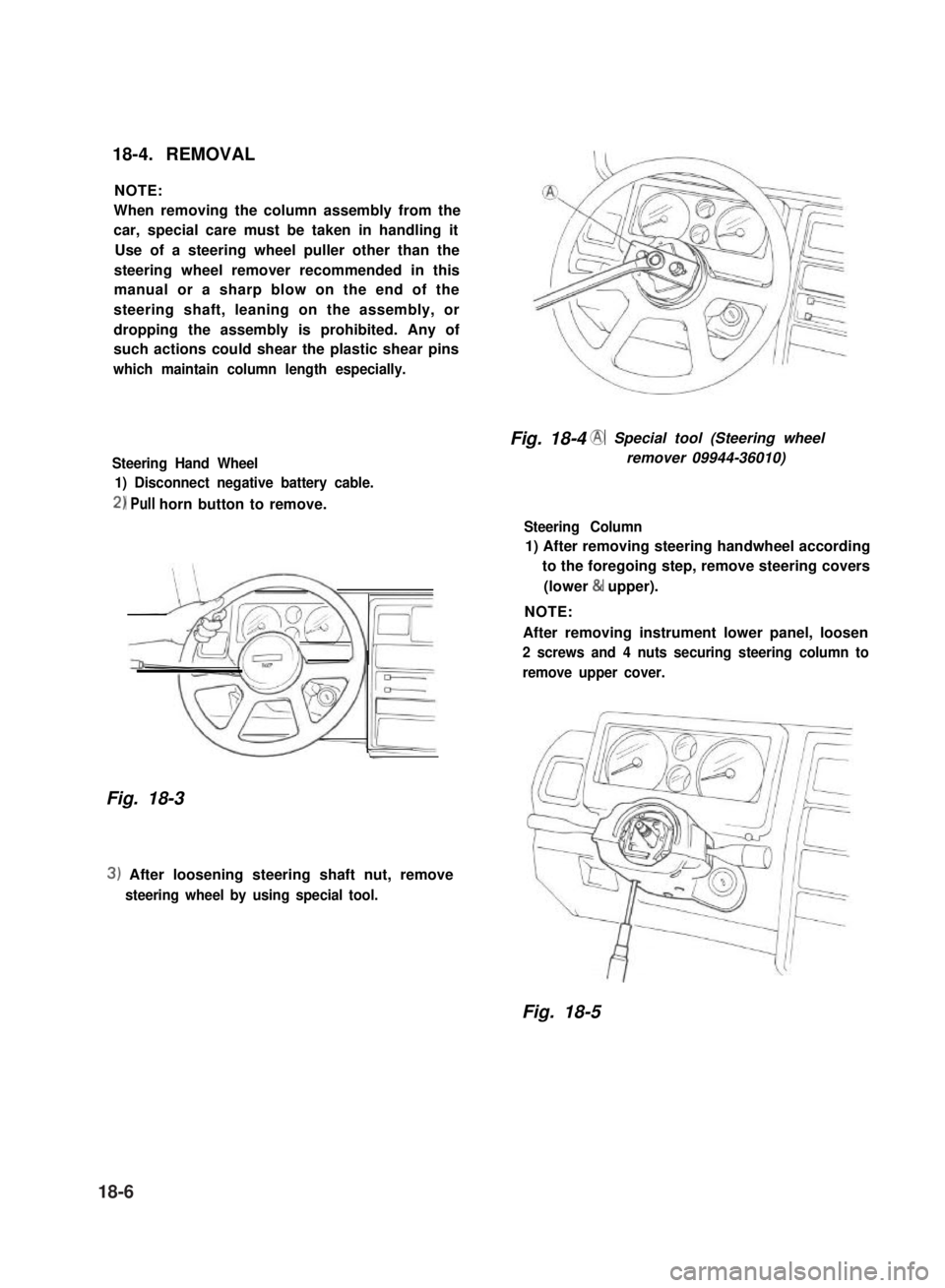
18-4. REMOVAL
NOTE:
When removing the column assembly from the
car, special care must be taken in handling it
Use of a steering wheel puller other than the
steering wheel remover recommended in this
manual or a sharp blow on the end of the
steering shaft, leaning on the assembly, or
dropping the assembly is prohibited. Any of
such actions could shear the plastic shear pins
which maintain column length especially.
Steering Hand Wheel
1) Disconnect negative battery cable.
2) Pull horn button to remove.
Fig. 18-3
3) After loosening steering shaft nut, remove
steering wheel by using special tool.
Fig. 18-4 @ Special tool (Steering wheel
remover 09944-36010)
Steering Column
1) After removing steering handwheel according
to the foregoing step, remove steering covers
(lower & upper).
NOTE:
After removing instrument lower panel, loosen
2 screws and 4 nuts securing steering column to
remove upper cover.
Fig. 18-5
18-6