1987 SUZUKI GRAND VITARA wheel alignment
[x] Cancel search: wheel alignmentPage 37 of 962
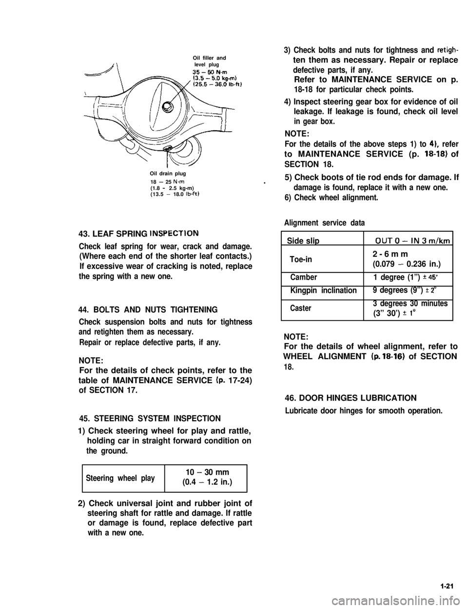
Oil filler andlevel plug
Oil drain plug
18 - 25 N.m(1.8 - 2.5 kg-m)(13.5 - 18.0 lb-ft)
43. LEAF SPRING lNSPECTlON
Check leaf spring for wear, crack and damage.
(Where each end of the shorter leaf contacts.)
If excessive wear of cracking is noted, replace
the spring with a new one.
44. BOLTS AND NUTS TIGHTENING
Check suspension bolts and nuts for tightness
and retighten them as necessary.
Repair or replace defective parts, if any.
NOTE:
For the details of check points, refer to the
table of MAINTENANCE SERVICE (p. 17-24)
of SECTION 17.
45. STEERING SYSTEM INSPECTION
1) Check steering wheel for play and rattle,
holding car in straight forward condition on
the ground.
Steering wheel play10 - 30 mm
(0.4 - 1.2 in.)
3) Check bolts and nuts for tightness and retigh-
ten them as necessary. Repair or replace
defective parts, if any.
Refer to MAINTENANCE SERVICE on p.
18-18 for particular check points.
4) Inspect steering gear box for evidence of oil
leakage. If leakage is found, check oil level
in gear box.
NOTE:
For the details of the above steps 1) to 41, refer
to MAINTENANCE SERVICE (p. 18-18) of
SECTION 18.
.5) Check boots of tie rod ends for damage. If
damage is found, replace it with a new one.
6) Check wheel alignment.
Alignment service data
Side slipOUTO-IN3m/km
Toe-in2-6mm
(0.079 - 0.236 in.)
Camber1 degree (1”) *45’
Kingpin inclination 9 degrees (9”) f 2’
Caster3 degrees 30 minutes
(3” 30’) f I0
NOTE:
For the details of wheel alignment, refer to
WHEEL ALIGNMENT (p. 18-16) of SECTION
18.
46. DOOR HINGES LUBRICATION
Lubricate door hinges for smooth operation.
2) Check universal joint and rubber joint of
steering shaft for rattle and damage. If rattle
or damage is found, replace defective part
with a new one.
1-21
Page 52 of 962

2-9. SUSPENSION, STEERING SYSTEM AND TIRES
Condition
Hard steering
Possible causeCorrection
1. Wheel tires not adequately inflatedAdjust the pressure
2. Bind in tie rod end ball studReplace
3. Linkage connections tending to seizeRepair or replace
4. Steering gearbox out of adjustmentAdjust as prescribed
5. Unevenly worn steering shaft bushReplace
6. Disturbed front wheel alignmentAdjust as prescribed
Wobbly steering wheel1. Wheel tires inflated unequallyAdjust tire pressure
(Shimmy, shake or2. Wobbly wheelsRepair or replace
vibration)3. Large difference in tire diameter betweenReplace._
right and left wheels
4. Loose hub nutsRetighten
5. Damaged or worn wheel bearingsReplace
6. Worn or loose tie rod endsReplace or retighten
7. Steering gearbox out of adjustmentAdjust as prescribed
8. Steering gearbox mounted looseRetighten
9. Worn steering knuckle oil sealReplace
10. Tire or wheel out of balanceBalance wheel or replace tire
and/or wheel
11. Blister or bump on tireReplace tire
12. Disturbed front wheel alignmentCheck front wheel alignment
Steering wheel
pulling to one
side (car pulls)
1. Unevenly worn wheel tires
2. Brake dragging in one road wheel
3. Wheel tires unequally inflated
4. Worn or distorted link rods
5. Disturbed front wheel alignment
6. Loose, bent or broken front or rear
suspension parts
Replace
Repair
Adjust tire pressure
Replace
Adjust as prescribed
Tighten or replace suspension
parts
Shocks coming to1. Tire inflating pressure too highReduce to the specification
steering wheel2. Poor shock absorber performanceReplace
(or wheel tramp)3. Differences in tire diameter among fourAdjust
road wheels
4. Worn steering linkage connectionsReplace
5. Worn or broken front wheel bearingsReplace
6. Loose front wheelRetighten
7. Steering wheel loose in placeRetighten the nut
8. Blister or bump on tireReplace tire
Rapid wear or uneven1. Wheel tires imporperly inflatedAdjust tire pressure
wear of wheel tires2. Differences in diameter among four tiresAdjust or replace
(Abnormal or excessive3. Worn or loose road wheel bearingsReplace
tire wear)4. Wobbly wheel tiresRepair or replace
2-14
Page 53 of 962
ConditionPossible causeCorrection
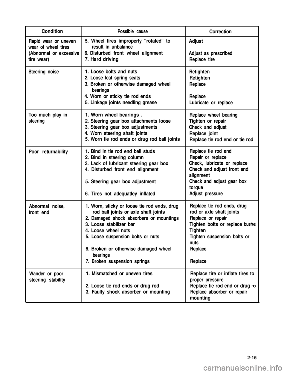
Rapid wear or uneven5. Wheel tires improperly “rotated“ toAdjust
wear of wheel tiresresult in unbalance
(Abnormal or excessive6. Disturbed front wheel alignmentAdjust as prescribed
tire wear)7. Hard drivingReplace tire
Steering noise1. Loose bolts and nuts
2. Loose leaf spring seats
3. Broken or otherwise damaged wheel
bearings
4. Worn or sticky tie rod ends
5. Linkage joints needling grease
Retighten
Retighten
Replace
Replace
Lubricate or replace
Too much play in
steering
1. Worn wheel bearings .Replace wheel bearing
2. Steering gear box attachments looseTighten or repair
3. Steering gear box adjustmentsCheck and adjust
4. Worn steering shaft jointsReplace joint
5. Worn tie rod ends or drug rod ball jointsReplace tie rod end or tie rod
Poor returnability1. Bind in tie rod end ball studs
2. Bind in steering column
3. Lack of lubricant steering gear box
4. Disturbed front end alignment
5. Steering gear box adjustment
6. Tires not adequatley inflated
Replace tie rod end
Repair or replace
Check, lubricate or replace
Check and adjust front end
alignment
Check and adjust gear box
torque
Adjust pressure
Abnormal noise,
front end
1. Worn, sticky or loose tie rod ends, drug
rod ball joints or axle shaft joints
2. Damaged shock absorbers or mountings
3. Loose stabilizer bar
4. Loose wheel nuts
5. Loose suspension bolts or nuts
6. Broken or otherwise damaged wheel
bearings
7. Broken suspension springs
Replace tie rod ends, drug
rod or axle shaft joints
Replace or repair
Tighten bolts or replace bushe!
Tighten
Tighten suspension bolts or
nuts
Replace
Replace
Wander or poor
steering stability
1. Mismatched or uneven tires
2. Loose tie rod ends or drug rod
3. Faulty shock absorber or mounting
Replace tire or inflate tires to
proper pressure
Replace tie rod end or drug ro(
Replace absorber or repair
mounting
2-15
Page 54 of 962
Condition
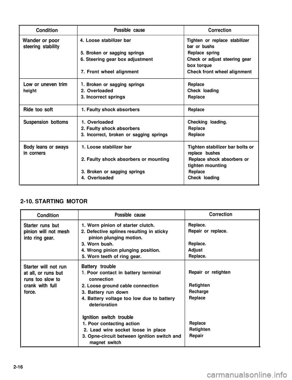
Wander or poor
steering stability
Low or uneven trim
height
Ride too soft
Suspension bottoms
Body leans or sways
in corners
Possible cause
4. Loose stabilizer bar
5. Broken or sagging springs
6. Steering gear box adjustment
7. Front wheel alignment
1. Broken or sagging springs
2. Overloaded
3. Incorrect springs
1. Faulty shock absorbers
1. Overloaded
2. Faulty shock absorbers
3. Incorrect, broken or sagging springs
1. Loose stabilizer bar
2. Faulty shock absorbers or mounting
3. Broken or sagging springs
4. Overloaded
Correction
Tighten or replace stabilizer
bar or bushs
Replace spring
Check or adjust steering gear
box torque
Check front wheel alignment
Replace
Check loading
Replace
Replace
Checking loading.
Replace
Replace
Tighten stabilizer bar bolts or
replace bushes
Replace shock absorbers or
tighten mounting
Replace
Check loading
STARTING MOTOR
Condition
Starter runs but
pinion will not mesh
into ring gear.
Starter will not run
at all, or runs but
runs too slow to
crank with full
force.
Possible cause
1. Worn pinion of starter clutch.
2. Defective splines resulting in sticky
pinion plunging motion.
3. Worn bush.
4. Wrong pinion plunging position.
5. Worn teeth of ring gear.
Battery trouble
1, Poor contact in battery terminal
connection
2. Loose ground cable connection
3. Battery run down
4. Battery voltage too low due to battery
deterioration
Correction
Replace.
Repair or replace.
Replace.
Adjust
Replace.
Repair or retighten
Retighten
Recharge
Replace
Ignition switch trouble
1. Poor contacting actionReplace
2. Lead wire socket loose in placeRetighten
3. Opne-circuit between ignition switch andRepair
magnet switch
2-10.
2-16
Page 364 of 962
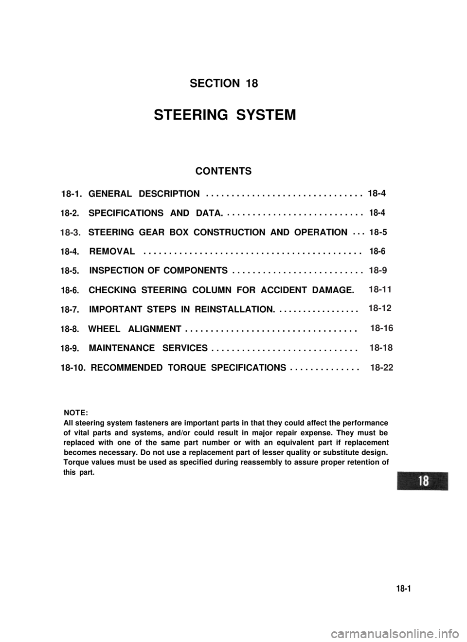
SECTION 18
STEERING SYSTEM
CONTENTS
18-1.GENERAL DESCRIPTION............................... 18-4
18-2.SPECIFICATIONS AND DATA............................18-4
STEERING GEAR BOX CONSTRUCTION AND OPERATION...18-5
18-4.REMOVAL...........................................18-6
18-5.INSPECTION OF COMPONENTS..........................
CHECKING STEERING COLUMN FOR ACCIDENT DAMAGE.
18-7.IMPORTANT STEPS IN REINSTALLATION..................
18-8.WHEEL ALIGNMENT..................................
18-9.MAINTENANCE SERVICES.............................
18-10. RECOMMENDED TORQUE SPECIFICATIONS..............
NOTE:
All steering system fasteners are important parts in that they could affect the performance
of vital parts and systems, and/or could result in major repair expense. They must be
replaced with one of the same part number or with an equivalent part if replacement
becomes necessary. Do not use a replacement part of lesser quality or substitute design.
Torque values must be used as specified during reassembly to assure proper retention of
this part.
18-1
18-3.
18-9
18-12
18-11
18-16
18-18
18-22
18-6.
Page 379 of 962
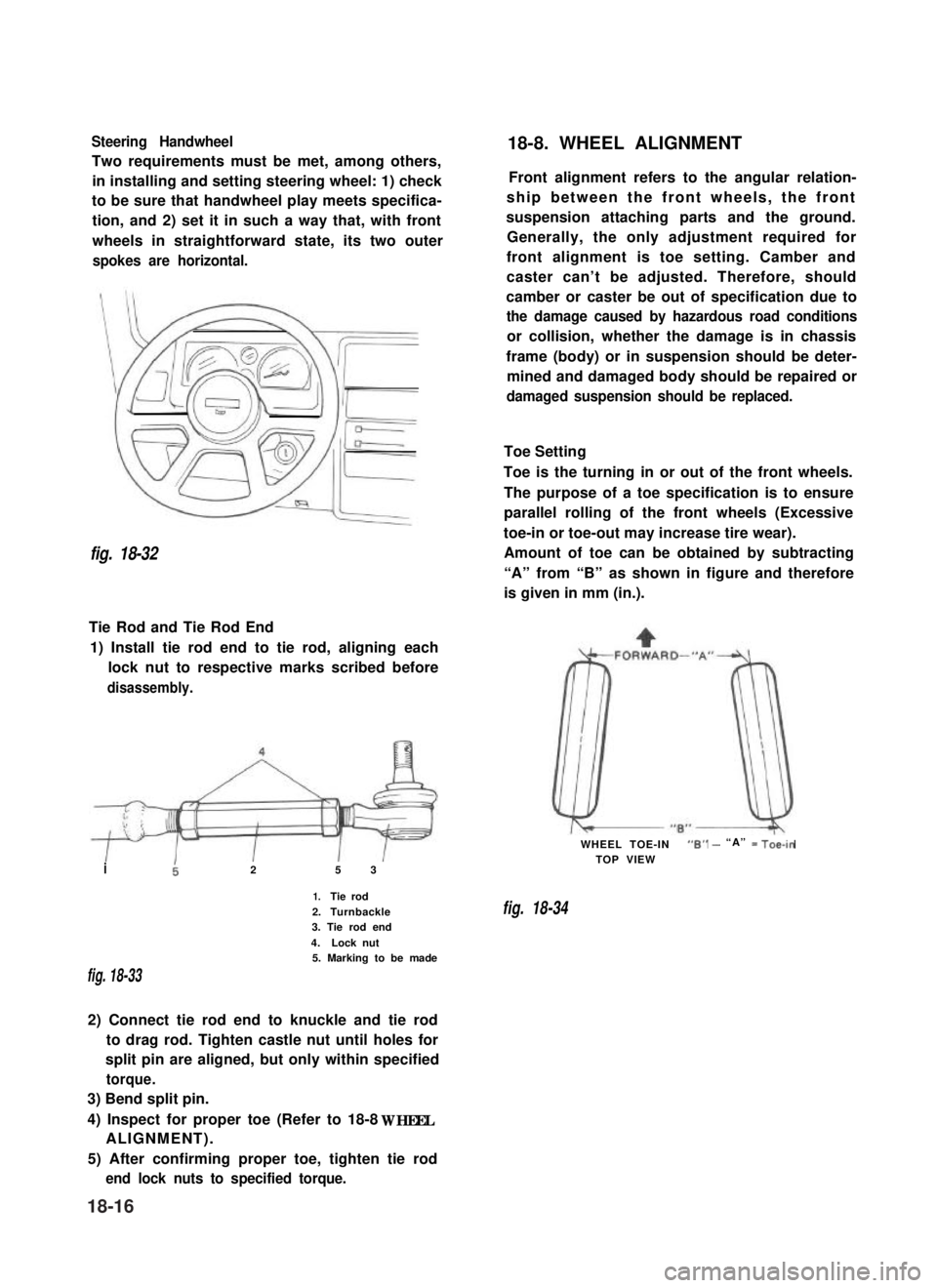
Steering Handwheel
Two requirements must be met, among others,
in installing and setting steering wheel: 1) check
to be sure that handwheel play meets specifica-
tion, and 2) set it in such a way that, with front
wheels in straightforward state, its two outer
spokes are horizontal.
fig. 18-32
Tie Rod and Tie Rod End
1) Install tie rod end to tie rod, aligning each
lock nut to respective marks scribed before
disassembly.
i25 3
1.Tie rod
2.Turnbackle3. Tie rod end
4.Lock nut5. Marking to be made
fig. 18-33
2) Connect tie rod end to knuckle and tie rod
to drag rod. Tighten castle nut until holes for
split pin are aligned, but only within specified
torque.
3) Bend split pin.
4) Inspect for proper toe (Refer to 18-8 WHEEL
ALIGNMENT).
5) After confirming proper toe, tighten tie rod
end lock nuts to specified torque.
18-8. WHEEL ALIGNMENT
Front alignment refers to the angular relation-
ship between the front wheels, the front
suspension attaching parts and the ground.
Generally, the only adjustment required for
front alignment is toe setting. Camber and
caster can’t be adjusted. Therefore, should
camber or caster be out of specification due to
the damage caused by hazardous road conditions
or collision, whether the damage is in chassis
frame (body) or in suspension should be deter-
mined and damaged body should be repaired or
damaged suspension should be replaced.
Toe Setting
Toe is the turning in or out of the front wheels.
The purpose of a toe specification is to ensure
parallel rolling of the front wheels (Excessive
toe-in or toe-out may increase tire wear).
Amount of toe can be obtained by subtracting
“A” from “B” as shown in figure and therefore
is given in mm (in.).
WHEEL TOE-IN“6” - “A” = Toe-in
TOP VIEW
fig. 18-34
18-16
Page 380 of 962
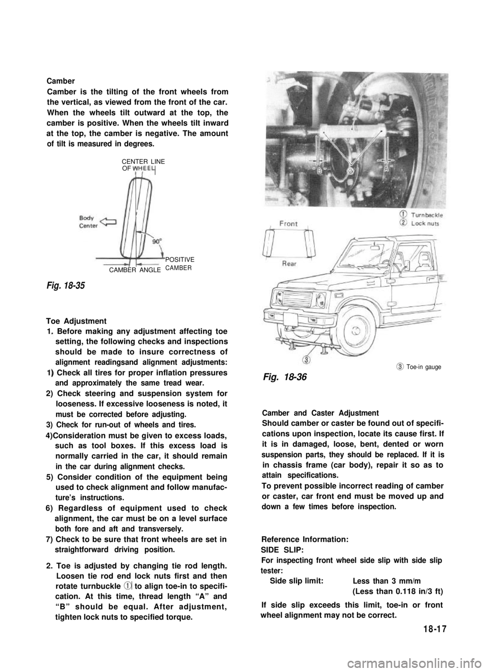
Camber
Camber is the tilting of the front wheels from
the vertical, as viewed from the front of the car.
When the wheels tilt outward at the top, the
camber is positive. When the wheels tilt inward
at the top, the camber is negative. The amount
of tilt is measured in degrees.
CENTER LINEOF yH,EEL
Fig. 18-35
CAMBER ANGLE
‘POSITIVE
CAMBER
Toe Adjustment
1. Before making any adjustment affecting toe
setting, the following checks and inspections
should be made to insure correctness of
alignment readingsand alignment adjustments:
1) Check all tires for proper inflation pressures
and approximately the same tread wear.
2) Check steering and suspension system for
looseness. If excessive looseness is noted, it
must be corrected before adjusting.
3) Check for run-out of wheels and tires.
4)Consideration must be given to excess loads,
such as tool boxes. If this excess load is
normally carried in the car, it should remain
in the car during alignment checks.
5) Consider condition of the equipment being
used to check alignment and follow manufac-
ture’s instructions.
6) Regardless of equipment used to check
alignment, the car must be on a level surface
both fore and aft and transversely.
7) Check to be sure that front wheels are set in
straightforward driving position.
2. Toe is adjusted by changing tie rod length.
Loosen tie rod end lock nuts first and then
rotate turnbuckle @ to align toe-in to specifi-
cation. At this time, thread length “A” and
“B” should be equal. After adjustment,
tighten lock nuts to specified torque.
@ Toe-in gauge
Fig. 18-36
Camber and Caster Adjustment
Should camber or caster be found out of specifi-
cations upon inspection, locate its cause first. If
it is in damaged, loose, bent, dented or worn
suspension parts, they should be replaced. If it is
in chassis frame (car body), repair it so as to
attain specifications.
To prevent possible incorrect reading of camber
or caster, car front end must be moved up and
down a few times before inspection.
Reference Information:
SIDE SLIP:
For inspecting front wheel side slip with side slip
tester:
Side slip limit:Less than 3 mm/m
(Less than 0.118 in/3 ft)
If side slip exceeds this limit, toe-in or front
wheel alignment may not be correct.
18-17