1987 SUZUKI GRAND VITARA bulb
[x] Cancel search: bulbPage 185 of 962
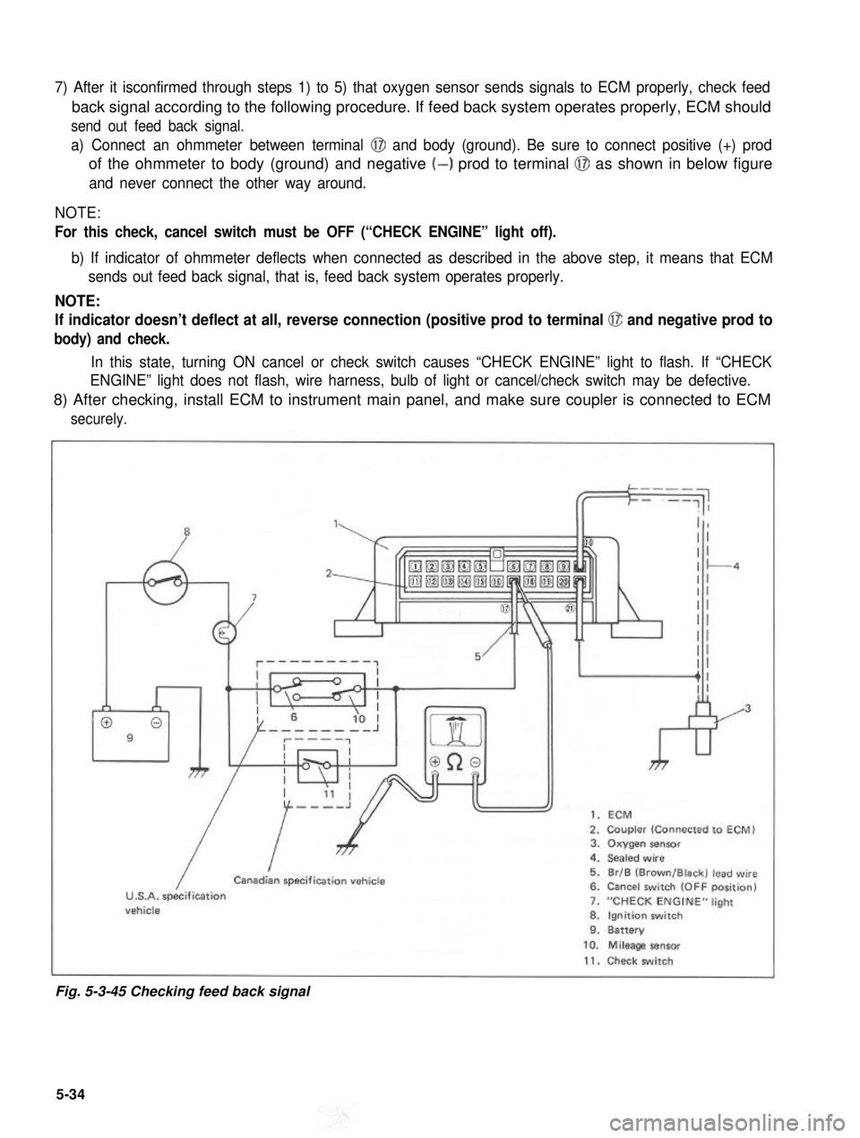
7) After it isconfirmed through steps 1) to 5) that oxygen sensor sends signals to ECM properly, check feed
back signal according to the following procedure. If feed back system operates properly, ECM should
send out feed back signal.
a) Connect an ohmmeter between terminal @I and body (ground). Be sure to connect positive (+) prod
of the ohmmeter to body (ground) and negative (-) prod to terminal @J as shown in below figure
and never connect the other way around.
NOTE:
For this check, cancel switch must be OFF (“CHECK ENGINE” light off).
b) If indicator of ohmmeter deflects when connected as described in the above step, it means that ECM
sends out feed back signal, that is, feed back system operates properly.
NOTE:
If indicator doesn’t deflect at all, reverse connection (positive prod to terminal @ and negative prod to
body) and check.
In this state, turning ON cancel or check switch causes “CHECK ENGINE” light to flash. If “CHECK
ENGINE” light does not flash, wire harness, bulb of light or cancel/check switch may be defective.
8) After checking, install ECM to instrument main panel, and make sure coupler is connected to ECM
securely.
”1,
009
7
kr
1. ECM
2. Coupler (Connected to ECM)3. Oxygen sensor4. Sealed wire
5. Br/B (Brown/Black) lead wire6. Cancel switch (OFF position)
7. “CHECK ENGINE” light
8. Ignition switch9. Battery
/
ICanadian specification vehicle
U.S.A. specificationvehicle
10. Mileage sensor
11. Check switch
Fig. 5-3-45 Checking feed back signal
5-34
Page 217 of 962
I
Generator (Pickup
coil) resistance130 - 190 ohmsI
1
1. White wire2. Red wire
Fig. 8-14
5. After checking, connect red and white wires
to ignitor as shown in Figure 8-15, and then
install dust cover.
NOTE:
NEVER connect red and white wires reversely.
Reverse connection may cause damage to
generator and ignitor.
1. White wire2. Red wire
3. lgnitor
4. Generator
Fig. 8-15
6. After generator has been assembled on
distributor, make sure to adjust air gap and
install ignitor.
7. Install distributor referring to page 8-11.
[ Ignitorl
1. Disconnect negative cable at battery. Remove
distributor, and then ignitor and generator.
2. Remove dust cover from ignitor.
3. Disconnect red and white wires from ignitor.
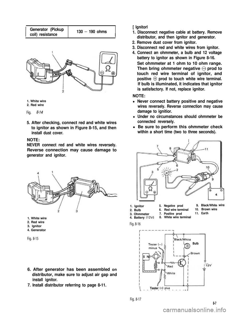
4. Connect an ohmmeter, a bulb and 12 voltage
battery to ignitor as shown in Figure 8-16.
Set ohmmeter at 1 ohm to 10 ohm range.
Then bring ohmmeter negative @ prod to
touch red wire terminal of ignitor, and
positive @ prod to touch white wire terminal.
If bulb is illuminated, it indicates that ignitor
is satisfactory. If not, replace ignitor.
NOTE:
l Never connect battery positive and negative
wires reversely. Reverse connection may cause
damage to ignitior.
l Under no circumstances should ohmmeter be
connected reversely.
l Be sure to perform this ohmmeter check
within a short time (two to three seconds).
1
1. lgnitor5.Negative prod9.Black/Whitewire
2. Bulb6.Red wire terminal10.Brown wire
3. Ohmmeter7.Positive prod11.Earth
4. Battery (12V)8.White wire terminal
Fig. 8-16
c---------~
Bulb
T_-.
ITester (+) PIUSL------------
Fig. 8-17
8-7
Page 450 of 962
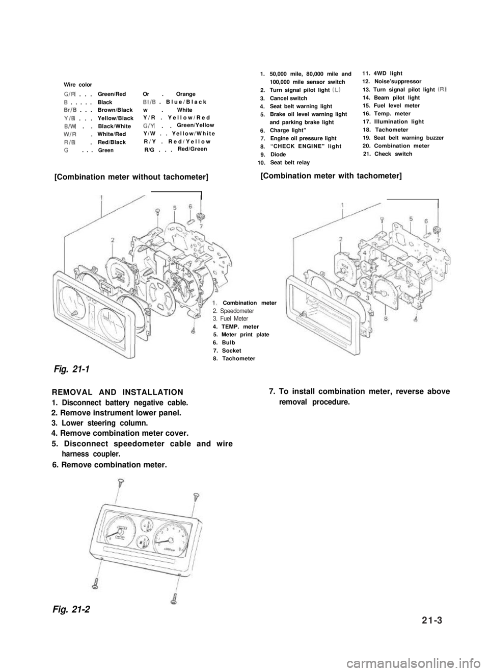
Wire color
G/R . . .Green/RedOr . Orange
0 . . . . .BlackBI/B . Blue/Black
0rlB . . .Brown/Blackw . White
Y/B . . .Yellow/BlackY/R . Yellow/Red
B/W . .Black/WhiteG/Y . .Green/Yellow
W/R .White/RedY/W . . Yellow/White
RIB .Red/BlackR/Y . Red/Yellow
G. . .GreenR/G . . .Red/Green
1.
2.
3.
4.
5.
6.7.
8.
9.
10.
50,000 mile, 80,000 mile and11. 4WD light
100,000 mile sensor switch12. Noise’suppressor
Turn signal pilot light (Lb13. Turn signal pilot light (RI
Cancel switch14. Beam pilot light
Seat belt warning light15. Fuel level meter
Brake oil level warning light16. Temp. meter
and parking brake light17. Illumination light
Charge light”18. Tachometer
Engine oil pressure light19. Seat belt warning buzzer
“CHECK ENGINE" light 20. Combination meter
Diode21. Check switch
Seat belt relay
[Combination meter without tachometer][Combination meter with tachometer]
4. TEMP. meter5. Meter print plate
6. Bulb
7. Socket
Combination meter
Fig. 21-1
8. Tachometer
REMOVAL AND INSTALLATION
1. Disconnect battery negative cable.
2. Remove instrument lower panel.
3. Lower steering column.
4. Remove combination meter cover.
5. Disconnect speedometer cable and wire
harness coupler.
7. To install combination meter, reverse above
removal procedure.
6. Remove combination meter.
Fig. 21-2
2. Speedometer3. Fuel Meter
21-3
Page 455 of 962
INSPECTION
1) Trouble diagnosis
Symptom
1. Lights will not come on in either left or
right group of light.
2. Hazard light comes on but turn signal
lights will not.
3. No light comes on; or lights light up but
do not flicker.
4. Turn signal lights are satisfactory, but
hazard light will not come on.
5. Flickering freueqncy is erratic, or lights
remain lit.
6. Turning on hazard warning switch lights up
only one group of lights.
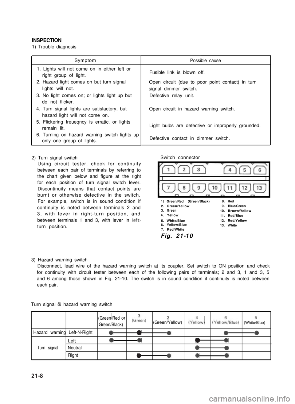
2) Turn signal switch
Using circuit tester, check for continuity
between each pair of terminals by referring to
the chart given below and figure at the right
for each position of turn signal switch lever.
Discontinuity means that contact points are
burnt or otherwise defective in the switch.
For example, switch is in sound condition if
continuity is noted between terminals 2 and
3, with lever in right-turn position, and
between terminals 1 and 3, with lever in left-
turn position.
Possible cause
Fusible link is blown off.
Open circuit (due to poor point contact) in turn
signal dimmer switch.
Defective relay unit.
Open circuit in hazard warning switch.
Light bulbs are defective or improperly grounded.
Defective contact in dimmer switch.
Switch connector
I”””yrm-
1.Green/Red (Green/Black)8.Red
2.Green/Yellow9.Blue/Green3.Green10.Brown/Yellow4.Yellow11.Red/Blue
5.White/Blue12.Red/Yellow6.Yellow/Blue13.White7.Red/White
Fig. 21-10
3) Hazard warning switch
Disconnect, lead wire of the hazard warning switch at its coupler. Set switch to ON position and check
for continuity with circuit tester between each of the following pairs of terminals; 2 and 3, 1 and 3, 5
and 6 among those shown in Fig. 21-10. The switch is in sound condition if continuity is noted between
each pair.
Turn signal & hazard warning switch
1(Green/Redor
Green/Black)
(Grien)2(Green/Yellow) (Yeiow)5(YelloiIBlue) (White/Blue)
Hazard warning Left-N-Right0a-000
Left00l0
Turn signalNeutral*0
Rightla*0
21-8
Page 458 of 962
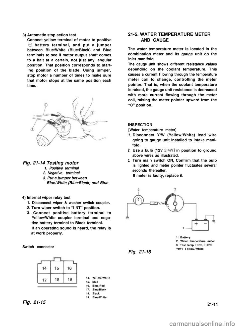
3) Automatic stop action test
Connect yellow terminal of motor to positive
@ battery terminal, and put a jumper
between Blue/White (Blue/Black) and Blue
terminals to see if motor output shaft comes
to a halt at a certain, not just any, angular
position. That position corresponds to start-
ing position of the blade. Using jumper,
stop motor a number of times to make sure
that motor stops at the same position each
time.
Fig. 21-14 Testing motor
1. Positive terminal
2. Negative terminal
3. Put a jumper between
Blue/White (Blue/Black) and Blue
4) Internal wiper relay test
1. Disconnect wiper & washer switch coupler.
2. Turn wiper switch to “I NT” position.
3. Connect positive battery terminal to
Yellow/White coupler terminal and nega-
tive battery terminal to Black terminal.
If an operating sound is heard, the relay is
at work properly.
Switch connector
14.Yellow/White
15.Blue16.Blue/Red17.Blue/Black
18.Black19.Blue/White
21-5. WATER TEMPERATURE METER
AND GAUGE
The water temperature meter is located in the
combination meter and its gauge unit on the
inlet manifold.
The gauge unit shows different resistance values
depending on the coolant temperature. This
causes a current f lowing through the temperature
meter coil to change, controlling the meter
pointer. That is, when the coolant temperature
is raised, the gauge unit resistance is decreased
with more current flowing through the meter
coil, raising the meter pointer upward from the
“C” position.
INSPECTION
[Water temperature meter]
1.
2.
3.
Disconnect Y/W (Yellow/White) lead wire
going to gauge unit installed to intake mani-
fold.
Use a bulb (12V 3.4W) in position to ground
above wires as illustrated.
Turn main switch ON, Confirm that the bulb
is lighted and meter pointer fluctuates several
seconds thereafter.
If meter is faulty, replace it.
1. Battery2. Water temperature meter
3. Test lamp (12V. 3.4W)YIW: Yellow/WhiteFig. 21-16
Fig. 21-1521-11
Page 459 of 962
![SUZUKI GRAND VITARA 1987 Service Repair Manual [Gauge unit] 21-6. FUEL LEVEL METER AND GAUGE
Warm up gauge unit. Thus make sure its resis-
tance is decreased with increase of temperature.
Temperature and resistance relationship can be
plotted in a SUZUKI GRAND VITARA 1987 Service Repair Manual [Gauge unit] 21-6. FUEL LEVEL METER AND GAUGE
Warm up gauge unit. Thus make sure its resis-
tance is decreased with increase of temperature.
Temperature and resistance relationship can be
plotted in a](/manual-img/20/57437/w960_57437-458.png)
[Gauge unit] 21-6. FUEL LEVEL METER AND GAUGE
Warm up gauge unit. Thus make sure its resis-
tance is decreased with increase of temperature.
Temperature and resistance relationship can be
plotted in a graph as shown below.
The fuel level meter circuit consists of the fuel
level meter installed inside the combination
meter and the fuel level gauge installed to the
fuel tank.
Fig. 21-17
wTemp.
Fig. 21-18 Resistance- Temp. Relationship
Temperature
50°C (122°F)
80°C (176°F)
100°C (212°F)
Resistance
133.9 -178.9 f-i
47.5-56.8 !a
26.2 -29.3 52
Current flowing through the meter coil is
changed to control the meter pointer. That is,
when fuel is full, the fuel level gauge unit
resistance is decreased with more current flowing
into the meter coil, causing the meter pointer
to point at the “F” position.
INSPECTION
[Fuel level meter]
1. Disconnect Y/R (Yellow/Red) lead wire
going to gauge unit.
2. Use a bulb (12V 3.4W) in position to ground
above lead wire as illustrated.
3. Turn ignition switch ON.
Make sure the bulb is lighted and meter
pointer fluctuates several seconds thereafter.
If meter is faulty, replace it.
Fig. 21-191. Battery2. Fuel level meter
3. Test lamp (12V. 3.4%‘)YR : Yellow/Red
NOTE:
Wind sealing tape on screw threads of gauge
before installing gauge to intake manifold.
21-12
Page 460 of 962
![SUZUKI GRAND VITARA 1987 Service Repair Manual [Gauge unit]21-7. BRAKE WARNING LAMP
Use ohmmeter to confirm that level gauge unit
changes in resistance with change of the float
position. Float position-to-resistance relation-
ship can be plotted i SUZUKI GRAND VITARA 1987 Service Repair Manual [Gauge unit]21-7. BRAKE WARNING LAMP
Use ohmmeter to confirm that level gauge unit
changes in resistance with change of the float
position. Float position-to-resistance relation-
ship can be plotted i](/manual-img/20/57437/w960_57437-459.png)
[Gauge unit]21-7. BRAKE WARNING LAMP
Use ohmmeter to confirm that level gauge unit
changes in resistance with change of the float
position. Float position-to-resistance relation-
ship can be plotted in a graph as shown below.
The brake warning lamp system consists of the
brake fluid level switch installed to the master
cylinder reservoir and the lamp inside the
combination meter.
This circuit includes a parking brake switch
which gives a warning for unreleased parking
brake.
F-E
Fig. 21-20 Resistance-Fuel Level Relationship
Fig. 21-21
F : Full
E : Empty
OPERATION
Brake fluid level warning lamp circuit consists of
brake fluid level switch installed in master
cylinder reservoir, brake fluid level warning lamp
in gage cluster and check relay.
Also, this circuit is additionally provided with
parking brake switch which warns that parking
brake is applied.when engine is stopped,
warning lamp comes on, if ignition switch is
turned ON and parking brake is applied.
For bulb check, warning lamp comes on briefly
during engine starting regardless of brake fluid
level position and parking brake operation.
Because point of check relay is closed.
After engine is started, release parking brake.
If lamp gose off, brake fluid level is adequate.
When warning lamp dose not operate, use circuit
diagram as reference to check bulb, wiring, etc.
r---i
check relayl-2-l
B/Y : Black/Yellow1. Fluid level switch
R/B : Red/Black2. Warning lamp
B: Black3. Parking brake switch
B/W : Black/White4. Main switch
B/BI : Black/Blue5. Battery
Fig. 27-22
21-13
Page 462 of 962
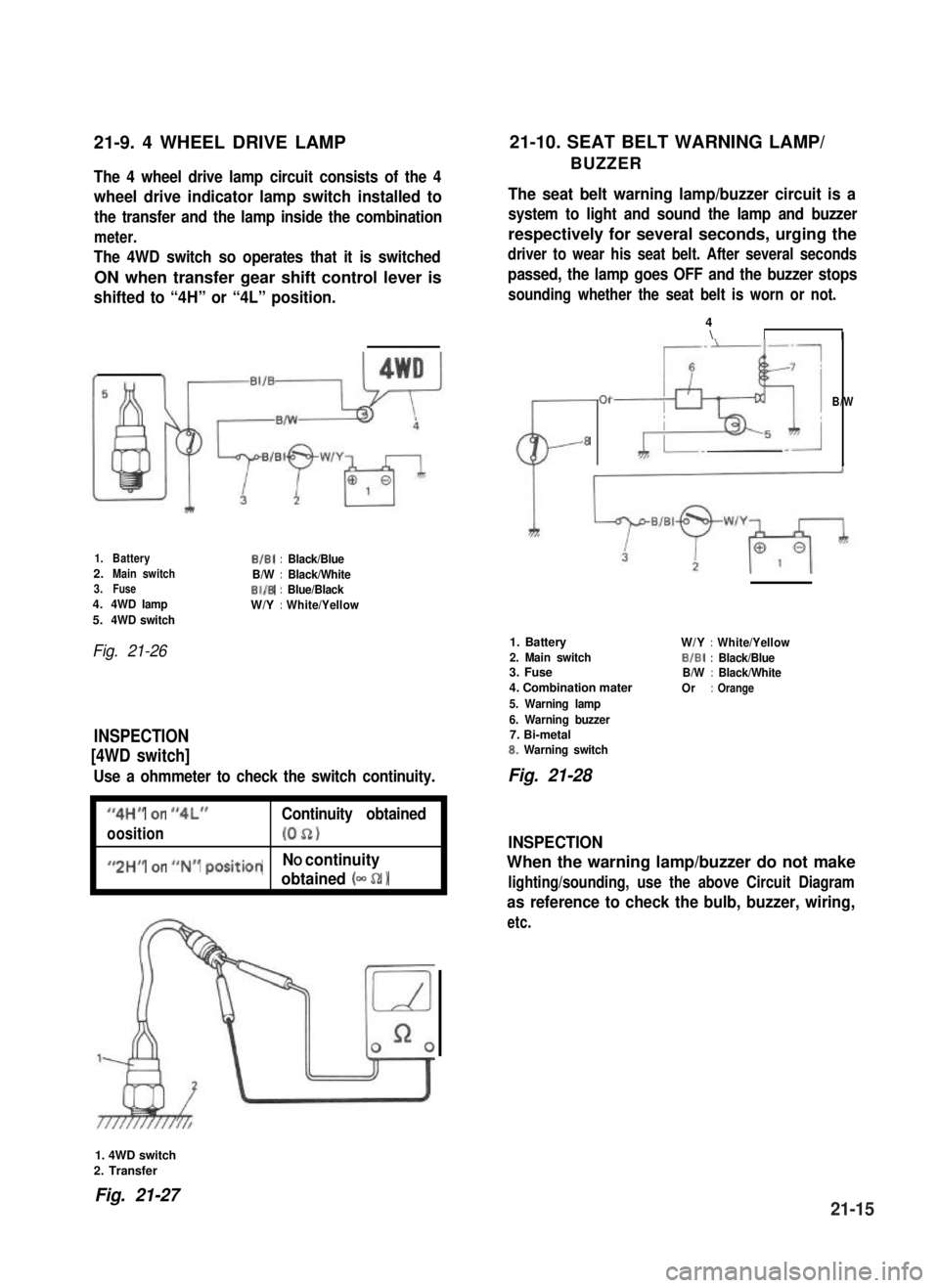
21-9. 4 WHEEL DRIVE LAMP21-10. SEAT BELT WARNING LAMP/
BUZZERThe 4 wheel drive lamp circuit consists of the 4
wheel drive indicator lamp switch installed to
the transfer and the lamp inside the combination
meter.
The 4WD switch so operates that it is switched
ON when transfer gear shift control lever is
shifted to “4H” or “4L” position.
The seat belt warning lamp/buzzer circuit is a
system to light and sound the lamp and buzzer
respectively for several seconds, urging the
driver to wear his seat belt. After several seconds
passed, the lamp goes OFF and the buzzer stops
sounding whether the seat belt is worn or not.
1.BatteryB/B1:Black/Blue2.Main switchB/W:Black/White3.FuseBI/B:Blue/Black4.4WD lampW/Y:White/Yellow5.4WD switch
Fig. 21-26
INSPECTION
[4WD switch]
Use a ohmmeter to check the switch continuity.
I
“4H” or “4L”Continuity obtained
oosition(052)I
I
#,2HM or ##N## positionNO continuity
obtained (- 52 1I
CL-
01
8
4\II
B/W
1. Battery
2. Main switch3. Fuse
4. Combination mater
5. Warning lamp
6. Warning buzzer7. Bi-metal8. Warning switch
W/Y:White/Yellow
BIBI:Black/BlueB/W:Black/White
Or:Orange
Fig. 21-28
INSPECTION
When the warning lamp/buzzer do not make
lighting/sounding, use the above Circuit Diagram
as reference to check the bulb, buzzer, wiring,
etc.
1. 4WD switch
2. Transfer
Fig. 21-2721-15