Page 111 of 962

1) Remove cylinder head cover.
2) Remove ignitiontiming check window
rubber plug from clutch housing of trans-
mission case.
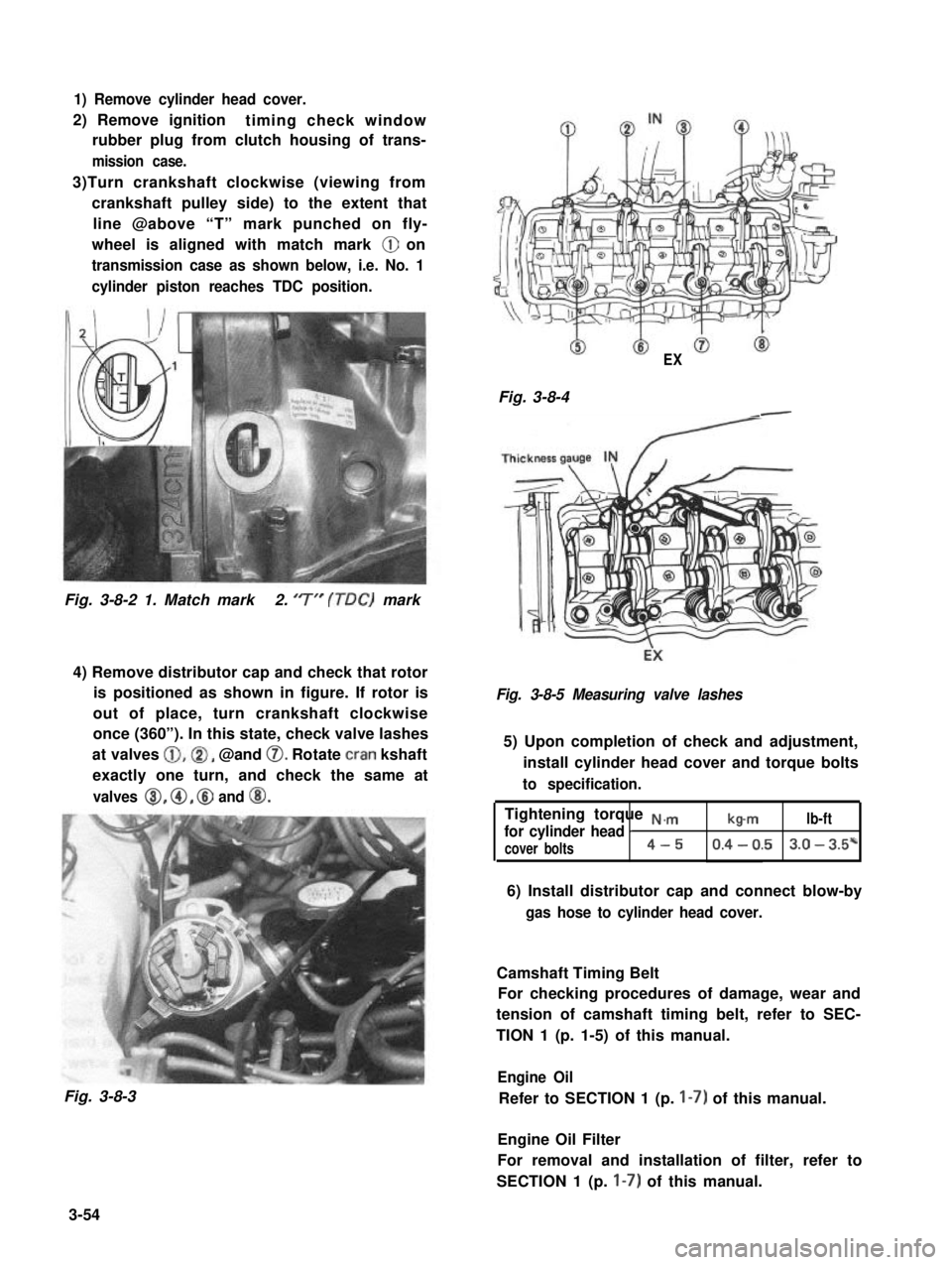
3)Turn crankshaft clockwise (viewing from
crankshaft pulley side) to the extent that
line @above “T” mark punched on fly-
wheel is aligned with match mark @ on
transmission case as shown below, i.e. No. 1
cylinder piston reaches TDC position.
Fig. 3-8-2 1. Match mark2. ‘7” (TDC) mark
4) Remove distributor cap and check that rotor
is positioned as shown in figure. If rotor is
out of place, turn crankshaft clockwise
once (360”). In this state, check valve lashes
at valves @,@I, @and 0. Rotate cran kshaft
exactly one turn, and check the same at
valves 8, @, @ and @I.
Fig. 3-8-3
EX
Fig. 3-8-4-
Fig. 3-8-5 Measuring valve lashes
5) Upon completion of check and adjustment,
install cylinder head cover and torque bolts
to specification.
Tightening torque N.,.,.,
for cylinder head Ib-mlb-ft
cover bolts4-50.4 - 0.53.0 - 3.5*
6) Install distributor cap and connect blow-by
gas hose to cylinder head cover.
Camshaft Timing Belt
For checking procedures of damage, wear and
tension of camshaft timing belt, refer to SEC-
TION 1 (p. 1-5) of this manual.
Engine Oil
Refer to SECTION 1 (p. I-7) of this manual.
Engine Oil Filter
For removal and installation of filter, refer to
SECTION 1 (p. I-7) of this manual.
3-54
Page 219 of 962

Ignition Timing
Ignition timing10” BTDC at
800 * 50 r/min
1 Ignition orderIl-3-4-2I
When checking and adjusting ignition timing,
be sure to use timing light (09900-27301 or
09900-27311).
NOTE:
Prior to check and adjustment of ignition timing,
make sure that head lights, heater fan, rear
defogger (if equipped), and air conditioner (if
equipped) are “OFF”. If any one of these
systems is “ON”,idle up system operates and
engine idle speed will be out of the specification.
[Checking]
1. Remove rubber plug from timing check
window on the transmission case.
2. Start engine and warm it up to normal operat-
ing temperature.
3. After warming up, check to be sure that idle
speed is within specification. If idle speed is
out of specification, adjust it by turning
idle speed adjusting screw of carburetor.
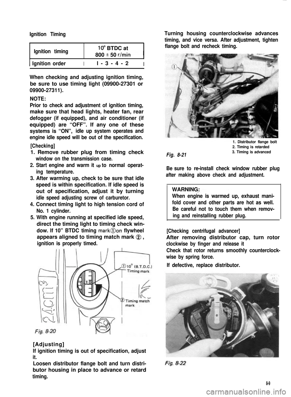
4. Connect timing light to high tension cord of
No. 1 cylinder.
5. With engine running at specified idle speed,
direct the timing light to timing check win-
dow. If 10” BTDC timing mark@on flywheel
appears aligned to timing match mark @ ,
ignition is properly timed.
Fig. 8-20
[Adjusting]
lf ignition timing is out of specification, adjust
it.
Loosen distributor flange bolt and turn distri-
butor housing in place to advance or retard
timing.
Turning housing counterclockwise advances
timing, and vice versa. After adjustment, tighten
flange bolt and recheck timing.
Fig. 8-21
1. Distributor flange bolt
2. Timing is retarded
3. Timing is advanced
Be sure to re-install check window rubber plug
after making above check and adjustment.
WARNING:
When engine is warmed up, exhaust mani-
fold cover and other parts are hot as well.
Be careful not to touch them when remov-
ing and reinstalling rubber plug.
[Checking centrifugal advancer]
After removing distributor cap, turn rotor
clockwise by finger and release it
Check that rotor returns smoothly counterclock-
wise by spring force.
If defective, replace distributor.
Fig. 8-22
8-9
Page 437 of 962
REMOVAL
Door Window Glass
1) Remove door window regulator handle.
Fig. 20-1-2
2) Remove inside handle case.
Fig. 20-1-3
3) Remove inside pull handle.
4) Loosen two screws securing the stopper
band, and take off the band.
5) Remove door trim board.
Fig. 20-1-5
6) Remove the door water proof film.
Fig. 20-1-6
7) Remove the glass inside and outside scrape.
Fig. 20-1-4 Fig. 20-1-7
20-3
Page 438 of 962
8) Remove 2 screws securing the door window
regulator roller holder (lower side).
Fig. 20-1-10
Fig. 20-1-8
9) Take out the glass.
Fig. 20-1-9
10) Detach glass from bottom channel.
Door Window Regulator
After carrying out door glass removal steps 1)
through 6) and 8), move on to the following
steps to take off the door window regulator.
1) Remove 2 screws securing the door window
regulator roller holder (upper side).
NOTE:
Make sure to support the glass to keep it from
falling while removing the screws.
2) Remove 4 screws securing the window regula-
tor.
Fig. 20-1-11
3) Remove the window regulator.
Fig. 20-1-12
20-4
Page 439 of 962
Fig. 20-1-13
Front Door Lock
After carrying out steps 1) through 6) of door
glass removal, move on to the following step to
take off the door lock.
After disconnecting each joint of control link,
remove the door inside handle and door lock
ass’y.
1. Plain screw driver
Fig. 20-1-14
INSTALLATION
Door Window Glass or Regulator
Reverse the removal sequence to install the door
window glass or regulator. However, be careful
of the following points.
[Door window regulator]
When installing door window regulator to door
panel, apply multi-purpose grease to the sliding
parts.
Fig. 20-1-15
[Door glass]
When fitting the glass bottom channel on the
door glass, adjust the distance between the glass
end (1) and channel end to that indicated
below.
Fig. 20-1-1642 mm (1.65 in.)
20-5
Page 440 of 962

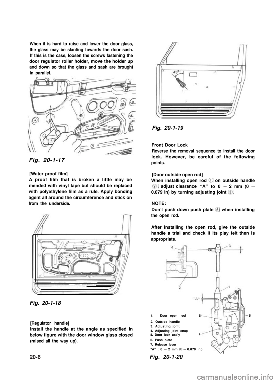
When it is hard to raise and lower the door glass,
the glass may be slanting towards the door sash.
If this is the case, loosen the screws fastening the
door regulator roller holder, move the holder up
and down so that the glass and sash are brought
in parallel.
Fig. 20-1-17
[Water proof film]
A proof film that is broken a little may be
mended with vinyl tape but should be replaced
with polyethylene film as a rule. Apply bonding
agent all around the circumference and stick on
from the underside.
Fig. 20-1-18
[Regulator handle]
Install the handle at the angle as specified in
below figure with the door window glass closed
(raised all the way up).
Fig. 20-1-19
Front Door Lock
Reverse the removal sequence to install the door
lock. However, be careful of the following
points.
[Door outside open rod]
When installing open rod @ on outside handle
0, adjust clearance“A” to 0 - 2 mm (0 -
0.079 in) by turning adjusting joint 0.
NOTE:
Don’t push down push plate @ when installing
the open rod.
After installing the open rod, give the outside
handle a trial and check if its play felt then is
appropriate.
1. Door rodopen65
2. Outside handle
3. Adjusting jomt4. Adjusting joint snap5. Door lock ass’y7
6. Push plate
7. Release lever
“A” : 0 - 2 mm (0-0.079in.)
Fig. 20-1-20
v
20-6
Page 442 of 962
20-2. WINDSHIELD
The windshield glass is bonded to the window panel (body) with weatherstrip in position. When replacing
the glass, it is necessary to perform correct operation and adhesive selection so that adequate bonding
strength can be obtained.
1. Windshield glass2. Windshield weatherstrip
Fig. 20-2-1
CLEANING
1) After removing the glass, remove the urethane
gum sticking to the glass and window panel
(body).
Fig. 20-2-2
NOTE:
When removing the urethane gum from the
window panel (body), apply a masking tape
along the edge of the gummed surface to protect
the painted surface from damage.
1. Urethane gum
Fig. 20-2-3
2. Use cleaning solvent to clean the glass and
window panel (body).
NOTE:
The use of alcohol or thinner when cleaning may
adversely affect some kinds of adhesives in
terms of bonding strength, resulting in that it is
impossible to obtain adequate strength for glass
installation. So, be careful sufficiently about the
selection of the cleaning solvent
20-8
Page 443 of 962

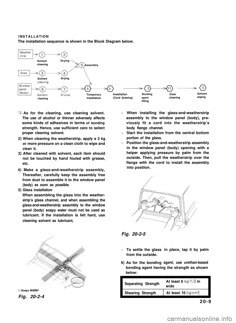
INSTALLATION
The installation sequence is shown in the Block Diagram below.
SolventcleaningDrying\rr05 Assembly
SolventDrying
4
-8-9F10-11B12
TemporaryinstallationInstallation(Cord drawing)Bondingagentfilling
Oozecleaning
Solventwipingcleaning
1) As for the cleaning, use cleaning solvent.
The use of alcohol or thinner adversely affects
some kinds of adhesives in terms of bonding
strength. Hence, use sufficient care to select
proper cleaning solvent.
2) When cleaning the weatherstrip, apply a 3 kg
or more pressure on a clean cloth to wipe and
clean it.
3) After cleaned with solvent, each item should
not be touched by hand fouled with grease,
etc.
4) Make a glass-and-weatherstrip assembly,
Thereafter, carefully keep the assembly free
from dust to assemble it to the window panel
(body) as soon as possible.
5) Glass installation
When assembling the glass into the weather-
strip’s glass channel, and when assembling the
glass-and-weatherstrip assembly to the window
panel (body) soapy water must not be used as
lubricant. If the installation is felt hard, use
cleaning solvent as lubricant,
1, Soapy water
Fig. 20-2-4
l When installing the glass-and-weatherstrip
assembly to the window panel (body), pre-
viously fit a cord into the weatherstrip’s
body flange channel.
l Start the installation from the central bottom
portion of the glass.
l Position the glass-and-weatherstrip assembly
in the window panel (body) opening with a
helper applying pressure by palm from the
outside. Then, pull the weatherstrip over the
flange with the cord to install the assembly
into position.
Fig. 20-2-5
l To settle the glass
from the outside.
in place, tap it by palm
6) As for the bondingagent, use urethan-based
bonding agent having the strength as shown
below:
ISeparating StrengthAt least 6 kg/l/2 in
wideI
Shearing StrengthAt least 10 kg/cm2I
20-9