1987 SUZUKI GRAND VITARA ESP
[x] Cancel search: ESPPage 15 of 962
O-5. METRIC INFORMATION
METRIC FASTENERS
Most of the fasteners used for this vehicle are
metric. When replacing any fasteners, it is most
important that replacement fasteners be the
correct diameter, thread pitch and strength.
FASTENER STRENGTH IDENTIFICATION
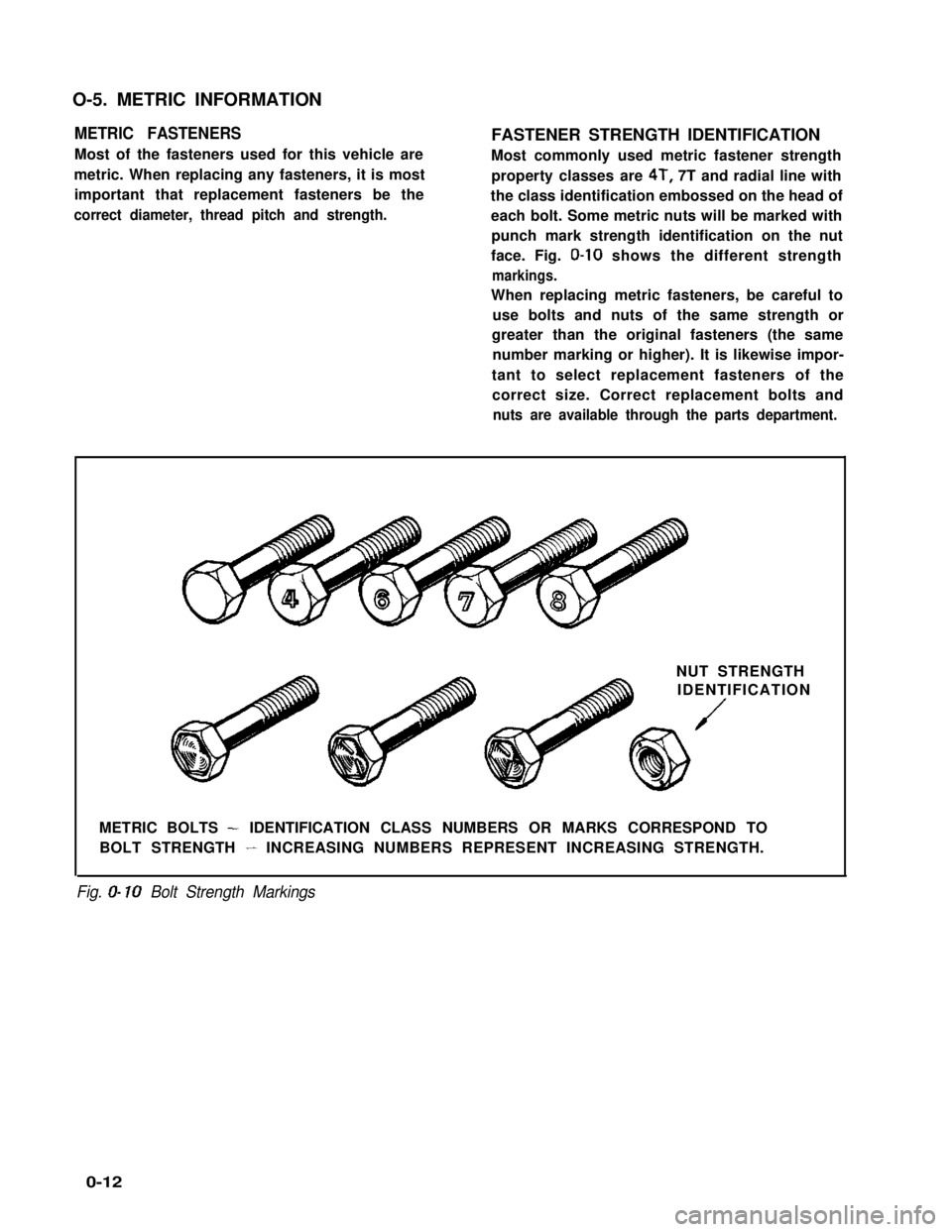
Most commonly used metric fastener strength
property classes are 4T, 7T and radial line with
the class identification embossed on the head of
each bolt. Some metric nuts will be marked with
punch mark strength identification on the nut
face. Fig. O-10 shows the different strength
markings.
When replacing metric fasteners, be careful to
use bolts and nuts of the same strength or
greater than the original fasteners (the same
number marking or higher). It is likewise impor-
tant to select replacement fasteners of the
correct size. Correct replacement bolts and
nuts are available through the parts department.
NUT STRENGTH
IDENTIFICATION
/
METRIC BOLTS - IDENTIFICATION CLASS NUMBERS OR MARKS CORRESPOND TO
BOLT STRENGTH - INCREASING NUMBERS REPRESENT INCREASING STRENGTH.
Fig. O- 10 Bolt Strength Markings
0-12
Page 20 of 962
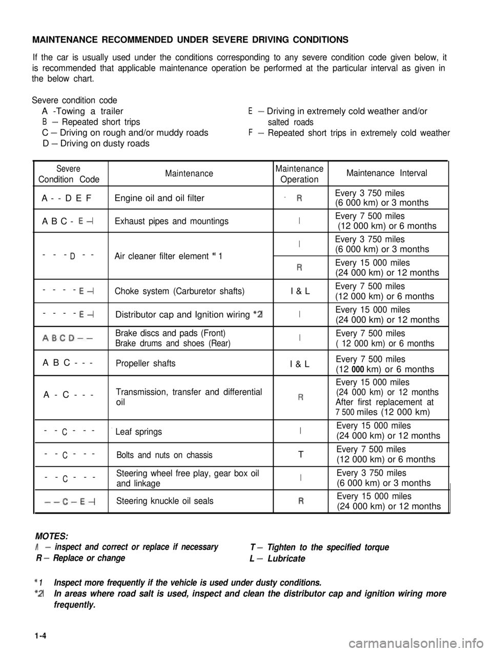
MAINTENANCE RECOMMENDED UNDER SEVERE DRIVING CONDITIONS
If the car is usually used under the conditions corresponding to any severe condition code given below, it
is recommended that applicable maintenance operation be performed at the particular interval as given in
the below chart.
Severe condition code
A -Towing a trailer
B- Repeated short trips
C - Driving on rough and/or muddy roads
D - Driving on dusty roads
E- Driving in extremely cold weather and/or
salted roads
F- Repeated short trips in extremely cold weather
Severe
Condition CodeMaintenanceMaintenance
OperationMaintenance Interval
A--DEFEngine oil and oil filter_ REvery 3 750 miles
(6 000 km) or 3 months
ABC- E-Exhaust pipes and mountingsIEvery 7 500 miles
(12 000 km) or 6 months
IEvery 3 750 miles
D(6 000 km) or 3 months--- --Air cleaner filter element * 1
REvery 15 000 miles
(24 000 km) or 12 months
----E-Choke system (Carburetor shafts)I&LEvery 7 500 miles
(12 000 km) or 6 months
----E-Distributor cap and Ignition wiring “2IEvery 15 000 miles
(24 000 km) or 12 months
ABCD--Brake discs and pads (Front)IEvery 7 500 miles
Brake drums and shoes (Rear)( 12 000 km) or 6 months
ABC---Propeller shaftsI&LEvery 7 500 miles
(12 000 km) or 6 months
Every 15 000 miles
A-C---Transmission, transfer and differential(24 000 km) or 12 months
oilRAfter first replacement at
7 500 miles (12 000 km)
CEvery 15 000 miles-- ---’ Leaf springsI(24 000 km) or 12 months
C-- ---Bolts and nuts on chassisTEvery 7 500 miles
(12 000 km) or 6 months
CSteering wheel free play, gear box oil-- ---and linkageIEvery 3 750 miles
(6 000 km) or 3 months
--C-E-Steering knuckle oil sealsREvery 15 000 miles
(24 000 km) or 12 months
MOTES:
I- inspect and correct or replace if necessary
R - Replace or change
T - Tighten to the specified torque
L - Lubricate
* 1Inspect more frequently if the vehicle is used under dusty conditions.
*2In areas where road salt is used, inspect and clean the distributor cap and ignition wiring more
frequently.
1-4
Page 42 of 962

ConditionPossible causeCorrection
Not enough powerEmission control
1. Malfunctioning EGR valve
Check and replace as
necessary.
Check and replace as
2. Malfunctioning bowl vent solenoid valve.necessary.
Check and replace as
3. Malfunctioning high altitude switch.necessary
Check nad replace as
4. Malfunctioning throttle position switch
(wide open switch)
necessary
Others
1. Dragging brakes
2. Slipping clutch
.Repair or replace
Adjust or replace
Engine hesitatesAbnormal condition in electrical systems
(Momentary lack of1. Defective spark plug or plug gap out ofReplace or adjust gap
response as the acceler-
ator
adjustment
is depressed. Can2. Cracked rotor or cap in distributor,Replace
occur at all car speeds.resulting in leakage
Usually most severe3. Deteriorated ignition coil, or crackReplace
when first trying toresulting in leakage
make the car move, as4. Leaky high-tension cordsReplace
from a stop sign.)5. Ignition timing out of adjustmentAdjust as prescribed
Abnormal condition in fuel system
1. Improper adjustment of float level
2. Clogged carburetor jets
3. Malfunctioning accelerator pump
Adjust
Clean
Check and replace as
necessary
4. Inadequately discharging fuel pumpReplace
Abnormal condition in engine
1. Loss of compression pressure due to leaky
cylinder head gasket
Replace
2. Compression pressure too low because ofReplace and rebore as
worn pistons, rings, cylinders or burnt valvesnecessary
Emission control
1. Malfunctioning bowl vent solenoid valveCheck and replace as
necessary
2. Malfunctioning throttle position switch
(wide open switch)
3. Malfunctionnig high altitude switch
4. Malfunctioning EGR valve
Check and replace as
necessary
Check and replace as
necessary
Check and replace as
necessary
5. Malfunctioning thermostatically controlled
air cleaner
Check and replace as
necessary
2-4
Page 80 of 962
Camshaftl Journal wear:
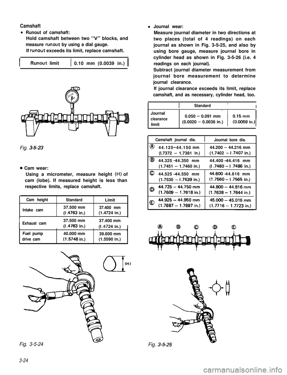
l Runout of camshaft:
Hold camshaft between two “V” blocks, and
measure runout by using a dial gauge.
If runout exceeds its limit, replace camshaft.
Measure journal diameter in two directions at
two places (total of 4 readings) on each
journal as shown in Fig. 3-5-25, and also by
using bore gauge, measure journal bore in
cylinder head as shown in Fig. 3-5-26 (i.e. 4
readings on each journal).
Subtract journal diameter measurement from
journal bore measurement to determine
journal clearance.
If journal clearance exceeds its limit, replace
camshaft, and as necessary, cylinder head, too.
IRunout limit1 0.10 mm (0.0039 in.) 1
Fig. 3-5-23
0 Cam wear:
Using a micrometer, measure height (H) of
cam (lobe). If measured height is less than
respective limits, replace camshaft.
Cam heightStandardLimit
Intake cam37.500 mm37.400 mm
(I .4763 in.)(1.4724 in.),
IExhaust cam37.500 mm37.400 mm
(I .4763 in.)(I .4724 in.)IrFuel pump40.000 mm39.600 mm
drive cam(I .5748 in.)(1.5590 in.)
Fig. 3-5-24
3-24
IIStandard1I
Journal
clearance
limit
0.050 - 0.091 mm
(0.0020 - 0.0036 in.)
Camshaft journal dia.Journal bore dia.
@44.125 44.150-mm44.200 - 44.216 mm
(I.7372 - 1.7381in.)(1.7402 - I .7407 in.)
@44.325 44.350 mm- 44.400 44.416 mm
(1.7451 - 1.7460 in.)(I .7480 - I .7486 in.)
044.525 44.550 mm-44~600 44.616 mm-
(1.7530 - I .7539 in.)(I .7560 - I .7565 in.)
Fig. 3-5-25
Page 88 of 962
inspect:
Check bearings for pitting, scratches, wear or
damage. If any malcondition is found, replace
both upper and lower halves. Never replace one
half without replacing the other half.
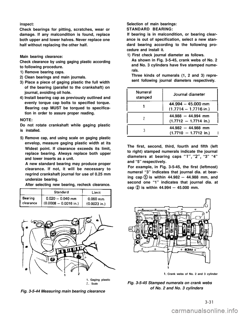
Main bearing clearance:
Check clearance by using gaging plastic according
to following procedure.
1) Remove bearing caps.
2) Clean bearings and main journals.
3) Place a piece of gaging plastic the full width
of the bearing (parallel to the crankshaft) on
journal, avoiding oil hole.
4) Install bearing cap as previously outlined and
evenly torque cap bolts to specified torque.
Bearing cap MUST be torqued to specifica-
tion in order to assure proper reading.
NOTE:
Do not rotate crankshaft while gaging plastic
is installed.
5) Remove cap, and using scale on gaging plastic
envelop, measure gaging plastic width at its
Widest point. If clearance exceeds its limit,
replace bearing. Always replace both upper
and lower inserts as a unit.
A new standard bearing may produce proper
clearance. If not, it will be necessary to
regrind crankshaft journal for use of 0.25 mm
undersize bearing.
After selecting new bearing, recheck clearance.
kj
1. Gaging plastic2. Scale
Fig. 3-5-44 Measuring main bearing clearance
Selection of main bearings:
STANDARD BEARING:
If bearing is in malcondition, or bearing clear-
ance is out of specification, select a new stan-
dard bearing according to the following pro-
cedure and install it.
1) First check journal diameter as follows.
As shown in Fig. 3-5-45, crank webs of No. 2
and No. 3 cylinders have five stamped nume-
rals.
Three kinds of numerals (1, 2 and 3) repre-
sent following journal diameters respectively.
I244.988 - 44.994 mm
(1.7712 - 1.7714 in.)I
I344.982 - 44.988 mm
(1.7710 - 1.7712 in.)I
The first, second, third, fourth and fifth (left
to right) stamped numerals indicate the journal
diameters at bearing caps “l”, “2”, “3” “4”
and “5” respectively.
For example, in Fig. 3-5-45, the first (leftmost)
numeral “3” indicates that journal dia. at bear-
ing cap 1 is within 44.982 - 44.988 mm, and
second one “1” indicates that journal dia. at
cap @ is within 44.994 - 45.000 mm.
1. Crank webs of No. 2 and 3 cylinder
Fig. 3-5-45 Stamped numerals on crank webs
of No. 2 and No. 3 cylinders
3-31
Page 89 of 962
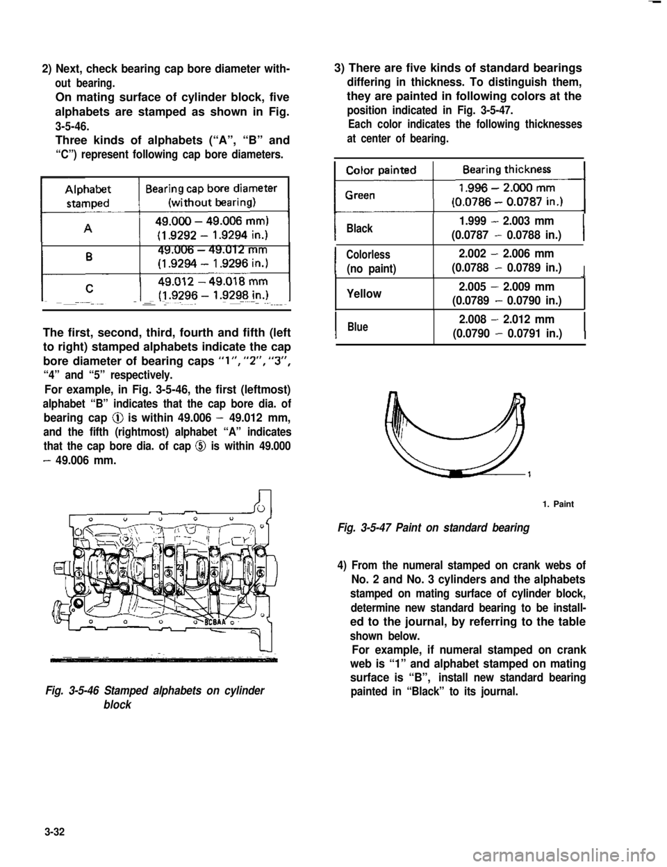
2) Next, check bearing cap bore diameter with-
out bearing.
On mating surface of cylinder block, five
alphabets are stamped as shown in Fig.
3-5-46.
Three kinds of alphabets (“A”, “B” and
“C”) represent following cap bore diameters.
The first, second, third, fourth and fifth (left
to right) stamped alphabets indicate the cap
bore diameter of bearing caps “l”, “2”, “3”,
“4” and “5” respectively.
For example, in Fig. 3-5-46, the first (leftmost)
alphabet “B” indicates that the cap bore dia. of
bearing cap @ is within 49.006 - 49.012 mm,
and the fifth (rightmost) alphabet “A” indicates
that the cap bore dia. of cap @ is within 49.000
- 49.006 mm.
Fig. 3-5-46 Stamped alphabets on cylinder
block
3) There are five kinds of standard bearings
differing in thickness. To distinguish them,
they are painted in following colors at the
position indicated in Fig. 3-5-47.
Each color indicates the following thicknesses
at center of bearing.
IBlack1.999 - 2.003 mm
(0.0787 - 0.0788 in.)I
I
Colorless2.002 - 2.006 mm
(no paint)(0.0788 - 0.0789 in.)I9
Yellow2.005 - 2.009 mm
(0.0789 - 0.0790 in.)
IBlue2.008 - 2.012 mm
(0.0790 - 0.0791 in.)I
1. Paint
Fig. 3-5-47 Paint on standard bearing
4) From the numeral stamped on crank webs of
No. 2 and No. 3 cylinders and the alphabets
stamped on mating surface of cylinder block,
determine new standard bearing to be install-
ed to the journal, by referring to the table
shown below.
For example, if numeral stamped on crank
web is “1” and alphabet stamped on mating
surface is “B”,install new standard bearing
painted in “Black” to its journal.
3-32
Page 124 of 962
![SUZUKI GRAND VITARA 1987 Service Repair Manual [Secondary main system]
Operation of the secondary throttle valve is also
controlled by the VTV and VSV. When the VSV
is closed, the vacuum to be applied to the
secondary diaphragm passes the VTV side SUZUKI GRAND VITARA 1987 Service Repair Manual [Secondary main system]
Operation of the secondary throttle valve is also
controlled by the VTV and VSV. When the VSV
is closed, the vacuum to be applied to the
secondary diaphragm passes the VTV side](/manual-img/20/57437/w960_57437-123.png)
[Secondary main system]
Operation of the secondary throttle valve is also
controlled by the VTV and VSV. When the VSV
is closed, the vacuum to be applied to the
secondary diaphragm passes the VTV side and
the secondary throttle valve opens gradually.
When the primary throttle valve opens almost
fully, the VSV opens according to the signal
from the ECM. Then the vacuum is applied
directly to the secondary diaphragm and the
secondary throttle valve responds to intensity of
vacuum. When the secondary throttle valve open-
ing is wider than when secondary slow system
operates, the fuel is discharged through the
secondary main jet and mixed with the air from
the secondary main air bleeder. The air/fuel
mixture is discharged into the carburetor bore
through the main discharge hole.
1. Secondary main jet2. Secondary main air bleeder
3. Main discharge hole4. Primary throttle valve
5. Secondary throttle valve
6.Secondarydiaphragm7.VTV
8.VSV
Acceleration Pump System
This system operates to supply extra fuel to the
primary side only during the acceleration.
When the primary throttle valve closes, the
return spring pushes up the pump piston. Then
the fuel pushes up the check ball and enters into
the pump cylinder. When the throttle valve opens
during the acceleration, simultaneously the
pump piston is pushed down by means of the
pump lever. Then the fuel in the pump cylinder
pushes up the discharge ball and the lower
injector weight and discharges into the carbure-
tor bore from the pump discharge nozzle.
In this way, a higher acceleration performance is
provided by this system.
1. Primary throttle valve
2.Return spring3.Pump piston
4.Check ball6.Pump cylinder
6.Plunger7.Pump lever8.Discharge ball
9.Injector weight10. Pump discharge nozzle11. Pump damper spring
Fig. 4- l- 10Acceleration pump s ys tern
Fig. 4-l-9 Secondary main system
4-9
Page 148 of 962
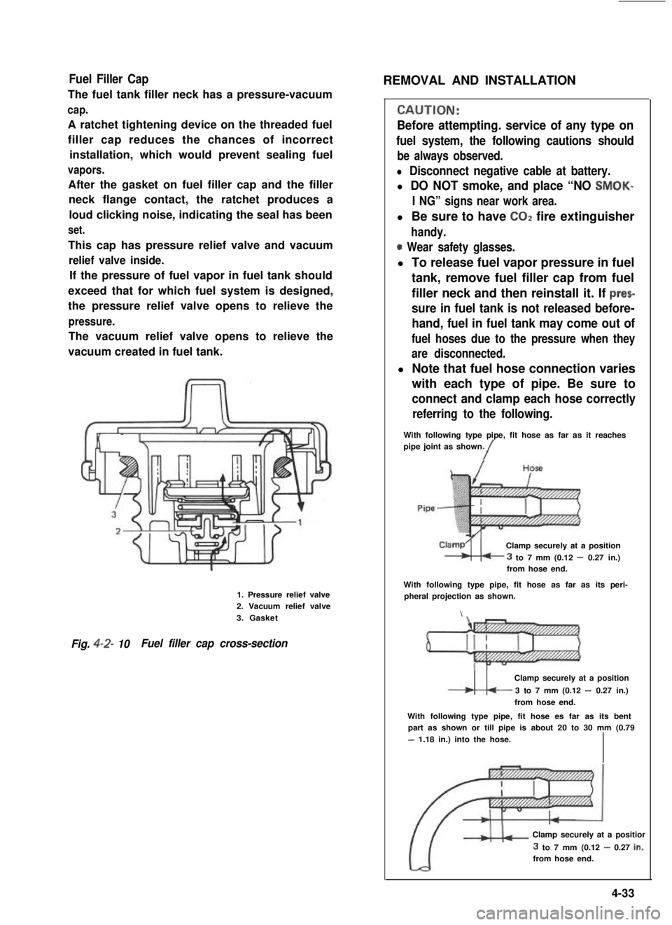
Fuel Filler Cap
The fuel tank filler neck has a pressure-vacuum
cap.
A ratchet tightening device on the threaded fuel
filler cap reduces the chances of incorrect
installation, which would prevent sealing fuel
vapors.
After the gasket on fuel filler cap and the filler
neck flange contact, the ratchet produces a
loud clicking noise, indicating the seal has been
set.
This cap has pressure relief valve and vacuum
relief valve inside.
If the pressure of fuel vapor in fuel tank should
exceed that for which fuel system is designed,
the pressure relief valve opens to relieve the
pressure.
The vacuum relief valve opens to relieve the
vacuum created in fuel tank.
1. Pressure relief valve2. Vacuum relief valve
3. Gasket
Fig. 4-2- 10Fuel filler cap cross-section
REMOVAL AND INSTALLATION
CALJTION:
Before attempting. service of any type on
fuel system, the following cautions should
be always observed.
l Disconnect negative cable at battery.
l DO NOT smoke, and place “NO SMOK-
I NG” signs near work area.
l Be sure to have COZ fire extinguisher
handy.
0 Wear safety glasses.
l To release fuel vapor pressure in fuel
tank, remove fuel filler cap from fuel
filler neck and then reinstall it. If prec
sure in fuel tank is not released before-
hand, fuel in fuel tank may come out of
fuel hoses due to the pressure when they
are disconnected.
l Note that fuel hose connection varies
with each type of pipe. Be sure to
connect and clamp each hose correctly
referring to the following.
With following type pipe, fit hose as far as it reachespipe joint as shown./
Clamp securely at a position
3 to 7 mm (0.12 - 0.27 in.)from hose end.
With following type pipe, fit hose as far as its peri-pheral projection as shown.
\
Clamp securely at a position
3 to 7 mm (0.12 - 0.27 in.)
from hose end.
With following type pipe, fit hose es far as its bentpart as shown or till pipe is about 20 to 30 mm (0.79
- 1.18 in.) into the hose.
Clamp securely at a positior
3 to 7 mm (0.12 - 0.27 in.:from hose end.
4-33