Page 395 of 962
The distance the lever (1) moves corresponds to
the amount of wear. In accordance with the
lever (1) movement, the fan-shaped ratchet (2)
also moves, for they are assembled as a unit. The
lever (1) and ratchet (2) remain in the positions
as they moved until the shoe-to-drum clearance
becomes even larger.
When the brake pedal is released, the brake shoe
is allowed to move back by the amount of
clearance “B” by means of the return spring. In
this way, the brake shoe-to-drum clearance is
automatically adjusted constant every time the
brake pedal is depressed.
The brake shoe-to-drum clearance “B” corre-
sponds to 0.6 - 0.8 mm (0.0236 - 0.0315 in.)
in terms of the brake drum diameter A tf A’.
And the amount adjusted by one notch of the
ratchet corresponds to 0.20 mm (0.008 in.) in
terms of the brake drum diameter A - A’.
The spring provided in the wheel cylinder
prevents the piston from moving back more than
the specified brake shoe-to-drum clearance.
Fig. 19-11
19-10
Page 418 of 962
INSPECTION
Inner Parts
NOTE:
After disassembly, soak all metal parts in ethyl
alcohol. Wipe rubber diaphragm and plastic parts
with a clean cloth. Use ethyl alcohol damped
cloth to wipe out heavy dirt Application of
much ethyl alcohol especially to rubber parts is
prohibited.
[ Rubber parts]
Wipe fluid from rubber parts and carefully
inspect each rubber part for cuts, nicks or other
damage. These parts are the key to the control
of air flow. If there is any question as to the
serviceability of rubber parts, REPLACE them.
[Metal parts]
BADLY DAMAGED ITEMS, OR THOSE
WHICH WOULD TAKE EXTENSIVE WORK
OR TIME TO REPAIR, SHOULD BE REPLAC-
ED. IN CASE OF DOUBT, INSTALL NEW
PARTS.
Inspection/Adjustment of Clearance Between
Booster Piston Rod and Master Cylinder Piston
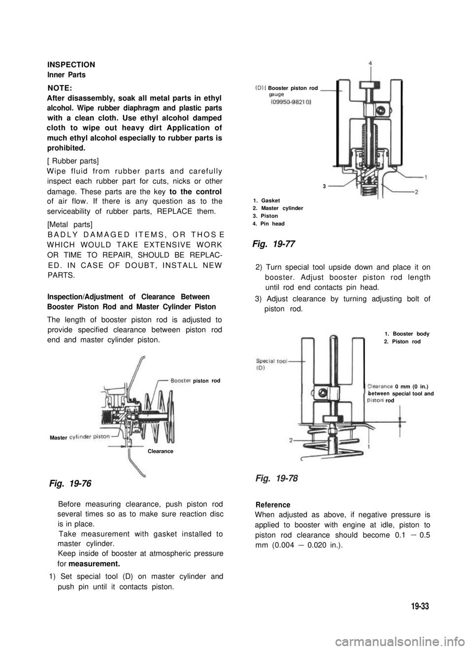
The length of booster piston rod is adjusted to
provide specified clearance between piston rod
end and master cylinder piston.
Master
Fig. 19-76
Clearance
(D): Booster piston rod -mwe
(09950-98210)
3
1. Gasket2. Master cylinder
3. Piston
4. Pin head
Fig. 19-77
2) Turn special tool upside down and place it on
booster. Adjust booster piston rod length
until rod end contacts pin head.
3) Adjust clearance by turning adjusting bolt of
piston rod.
pistonrod
Before measuring clearance, push piston rod
several times so as to make sure reaction disc
is in place.
Take measurement with gasket installed to
master cylinder.
Keep inside of booster at atmospheric pressure
for measurement.
1) Set special tool (D) on master cylinder and
push pin until it contacts piston.
1. Booster body
2. Piston rod
%arance 0 mm (0 in.)betweenspecial tool andiston rod
Reference
When adjusted as above, if negative pressure is
applied to booster with engine at idle, piston to
piston rod clearance should become 0.1 - 0.5
mm (0.004 - 0.020 in.).
19-33
Fig. 19-78
Page 452 of 962
HEADLIGHT INSPECTION
1.Lighting (Low beam, High beam, Passing)
2. Mounting
3.Dirt and cracks on lenses
4.Main beam axis direction and brightness
HEADLIGHT BEAM SETTING (STANDARD PROCEDURE)
Before setting the headlight beams, adjust air pressures of four tires to a specified value respectively. Move
the vehicle up and down by hand to settle its attitude. Then move it over a flat surface. There are available
a variety of headlight beams setting methods (e.g., the screen method using a focusing tester, etc.). How-
ever, the method described here does not use such tester.
Beam alignment
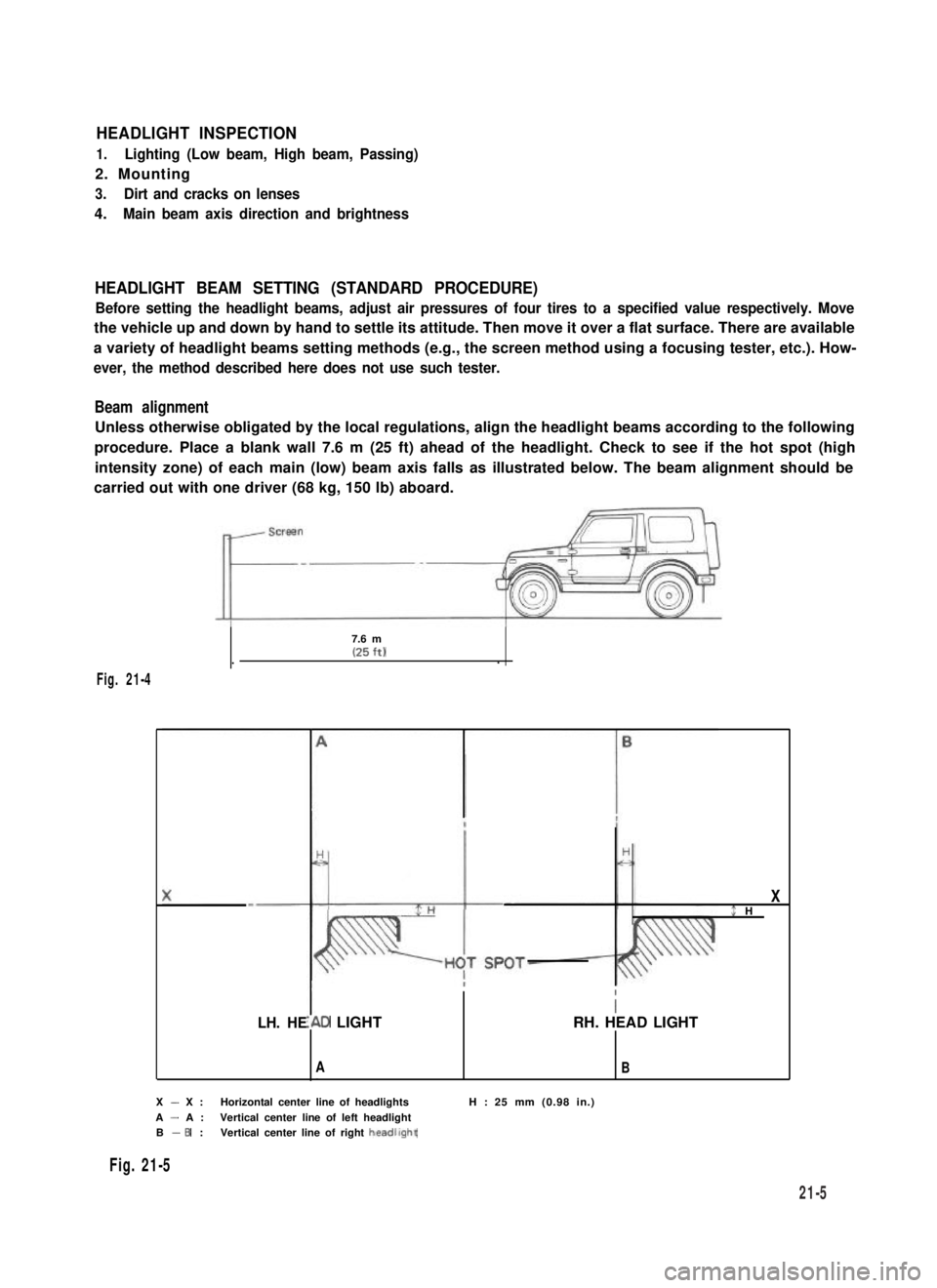
Unless otherwise obligated by the local regulations, align the headlight beams according to the following
procedure. Place a blank wall 7.6 m (25 ft) ahead of the headlight. Check to see if the hot spot (high
intensity zone) of each main (low) beam axis falls as illustrated below. The beam alignment should be
carried out with one driver (68 kg, 150 lb) aboard.
7.6 m(25 ft)..
Fig. 21-4
LH. HE
X$ H
I
I\D LIGHTRH. HEAD LIGHT
AB
X - X :Horizontal center line of headlightsH : 25 mm (0.98 in.)
A - A :Vertical center line of left headlightB - 6 :Vertical center line of right headllght
Fig. 21-5
21-5
Page 457 of 962
3-speed typer __-- - ---- - ---- ~-*
Fig. 21-12
rI-I
III
MI > p1p2
fil
II0POI--m--e----J
OFF
IN1
LOW
MAINTENANCE
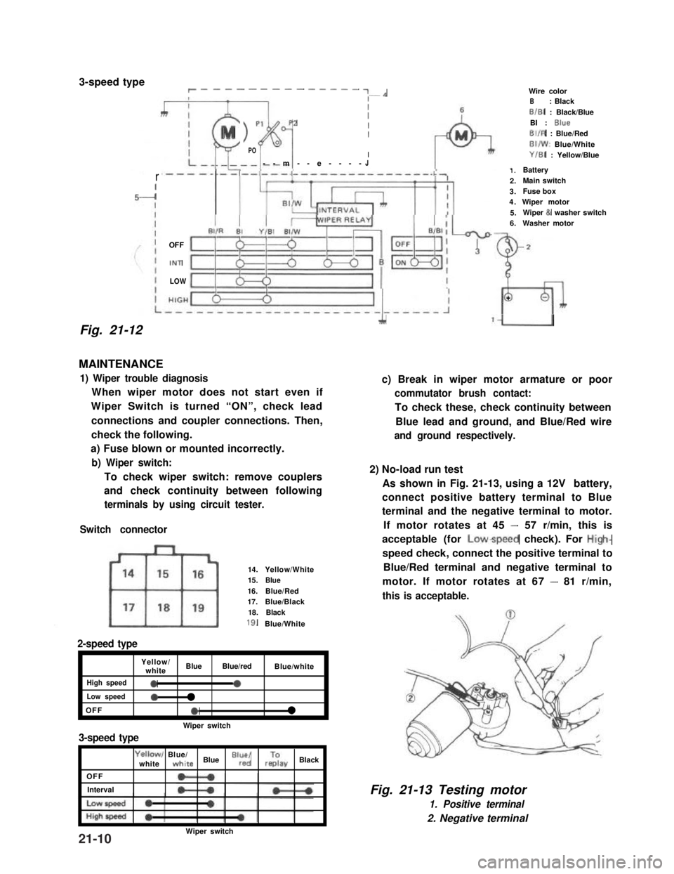
1) Wiper trouble diagnosis
When wiper motor does not start even if
Wiper Switch is turned “ON”, check lead
connections and coupler connections. Then,
check the following.
a) Fuse blown or mounted incorrectly.
b) Wiper switch:
To check wiper switch: remove couplers
and check continuity between following
terminals by using circuit tester.
Switch connector
14.Yellow/White15.Blue16.Blue/Red17.Blue/Black18.Black
18.Blue/White
2-speed type
Yellow/whiteBlueBlue/redBlue/white
High speed0a
Low speed0l
OFFel
Wiper switch
3-speed type
OFF
Interval
Yellowl Blue/whitewhite Blue “lr”,“d/ rzay Black
1.Battery2.Main switch3.Fuse box4.Wiper motor5.Wiper & washer switch6.Washer motor
Wire colorB: BlackB/B1 : Black/BlueBI : BlueBIIR : Blue/RedBI/W: Blue/WhiteY/B1 : Yellow/Blue
2
L
+
A‘U
c) Break in wiper motor armature or poor
commutator brush contact:
To check these, check continuity between
Blue lead and ground, and Blue/Red wire
and ground respectively.
2) No-load run test
As shown in Fig. 21-13, using a 12V battery,
connect positive battery terminal to Blue
terminal and the negative terminal to motor.
If motor rotates at 45 - 57 r/min, this is
acceptable (for Lowspeed check). For High-
speed check, connect the positive terminal to
Blue/Red terminal and negative terminal to
motor. If motor rotates at 67 - 81 r/min,
this is acceptable.
Fig. 21-13 Testing motor
1. Positive terminal
2. Negative terminal
Wiper switch21-10
Page 458 of 962
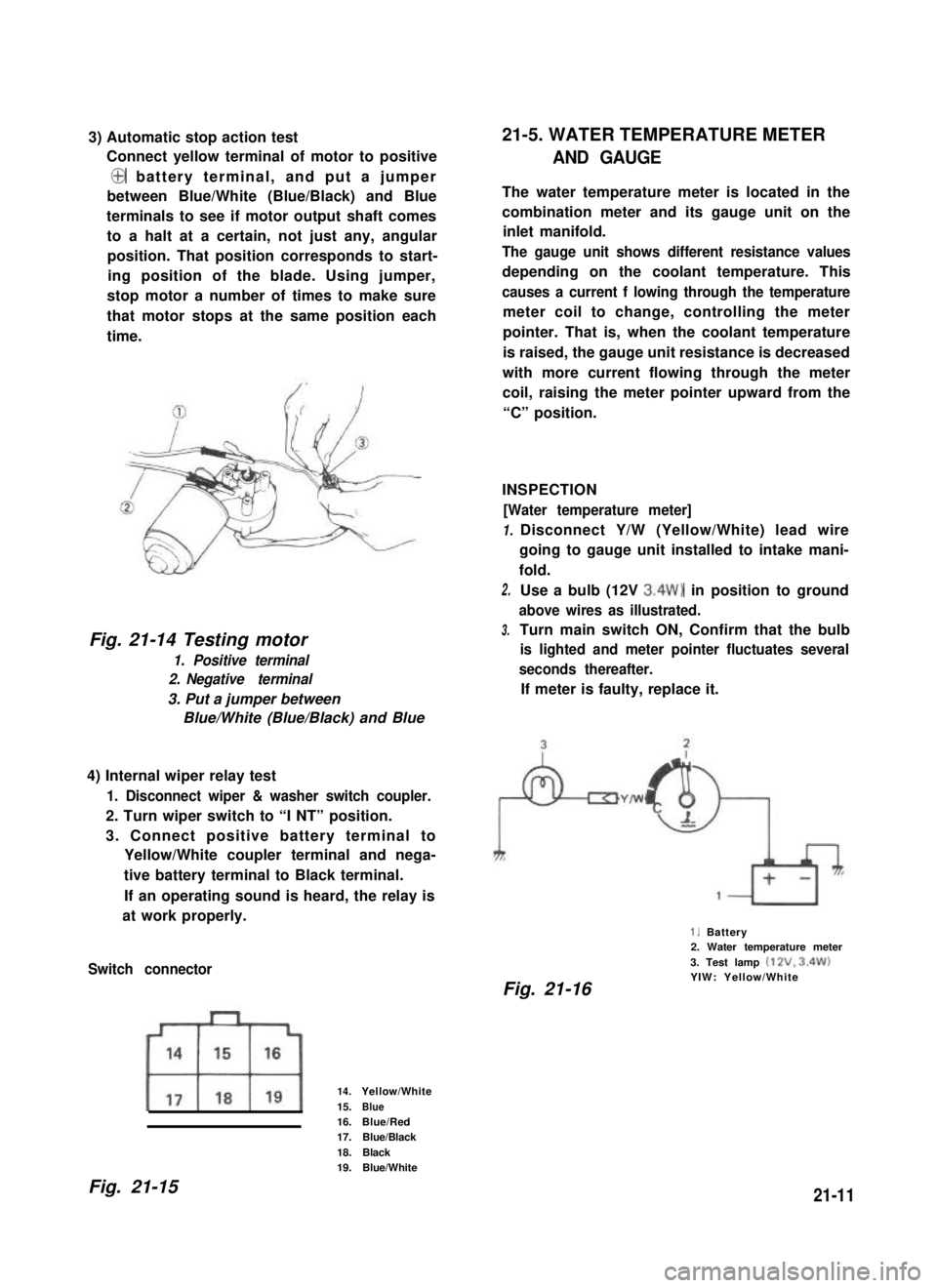
3) Automatic stop action test
Connect yellow terminal of motor to positive
@ battery terminal, and put a jumper
between Blue/White (Blue/Black) and Blue
terminals to see if motor output shaft comes
to a halt at a certain, not just any, angular
position. That position corresponds to start-
ing position of the blade. Using jumper,
stop motor a number of times to make sure
that motor stops at the same position each
time.
Fig. 21-14 Testing motor
1. Positive terminal
2. Negative terminal
3. Put a jumper between
Blue/White (Blue/Black) and Blue
4) Internal wiper relay test
1. Disconnect wiper & washer switch coupler.
2. Turn wiper switch to “I NT” position.
3. Connect positive battery terminal to
Yellow/White coupler terminal and nega-
tive battery terminal to Black terminal.
If an operating sound is heard, the relay is
at work properly.
Switch connector
14.Yellow/White
15.Blue16.Blue/Red17.Blue/Black
18.Black19.Blue/White
21-5. WATER TEMPERATURE METER
AND GAUGE
The water temperature meter is located in the
combination meter and its gauge unit on the
inlet manifold.
The gauge unit shows different resistance values
depending on the coolant temperature. This
causes a current f lowing through the temperature
meter coil to change, controlling the meter
pointer. That is, when the coolant temperature
is raised, the gauge unit resistance is decreased
with more current flowing through the meter
coil, raising the meter pointer upward from the
“C” position.
INSPECTION
[Water temperature meter]
1.
2.
3.
Disconnect Y/W (Yellow/White) lead wire
going to gauge unit installed to intake mani-
fold.
Use a bulb (12V 3.4W) in position to ground
above wires as illustrated.
Turn main switch ON, Confirm that the bulb
is lighted and meter pointer fluctuates several
seconds thereafter.
If meter is faulty, replace it.
1. Battery2. Water temperature meter
3. Test lamp (12V. 3.4W)YIW: Yellow/WhiteFig. 21-16
Fig. 21-1521-11
Page 462 of 962
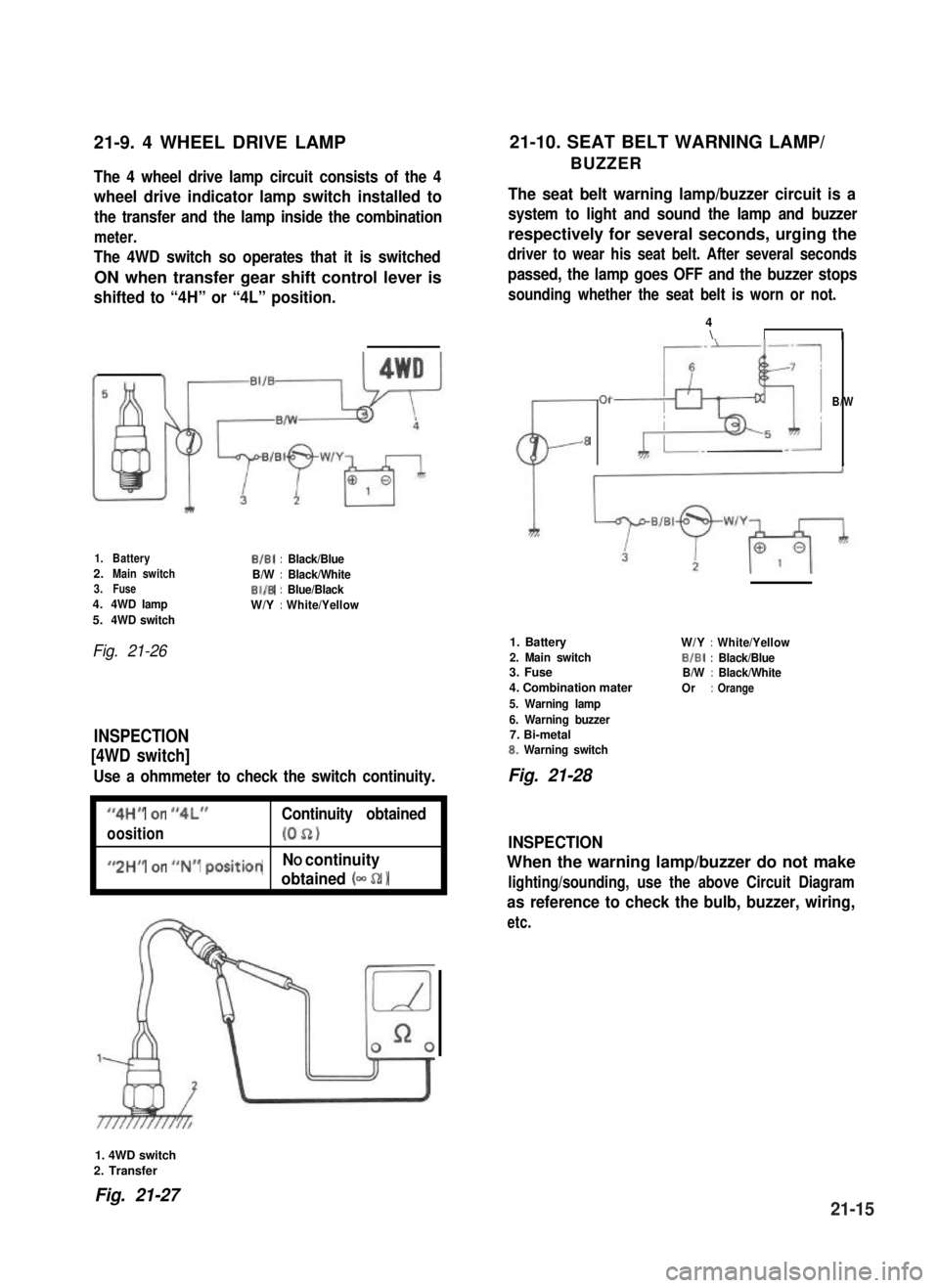
21-9. 4 WHEEL DRIVE LAMP21-10. SEAT BELT WARNING LAMP/
BUZZERThe 4 wheel drive lamp circuit consists of the 4
wheel drive indicator lamp switch installed to
the transfer and the lamp inside the combination
meter.
The 4WD switch so operates that it is switched
ON when transfer gear shift control lever is
shifted to “4H” or “4L” position.
The seat belt warning lamp/buzzer circuit is a
system to light and sound the lamp and buzzer
respectively for several seconds, urging the
driver to wear his seat belt. After several seconds
passed, the lamp goes OFF and the buzzer stops
sounding whether the seat belt is worn or not.
1.BatteryB/B1:Black/Blue2.Main switchB/W:Black/White3.FuseBI/B:Blue/Black4.4WD lampW/Y:White/Yellow5.4WD switch
Fig. 21-26
INSPECTION
[4WD switch]
Use a ohmmeter to check the switch continuity.
I
“4H” or “4L”Continuity obtained
oosition(052)I
I
#,2HM or ##N## positionNO continuity
obtained (- 52 1I
CL-
01
8
4\II
B/W
1. Battery
2. Main switch3. Fuse
4. Combination mater
5. Warning lamp
6. Warning buzzer7. Bi-metal8. Warning switch
W/Y:White/Yellow
BIBI:Black/BlueB/W:Black/White
Or:Orange
Fig. 21-28
INSPECTION
When the warning lamp/buzzer do not make
lighting/sounding, use the above Circuit Diagram
as reference to check the bulb, buzzer, wiring,
etc.
1. 4WD switch
2. Transfer
Fig. 21-2721-15
Page:
< prev 1-8 9-16 17-24