Page 163 of 962

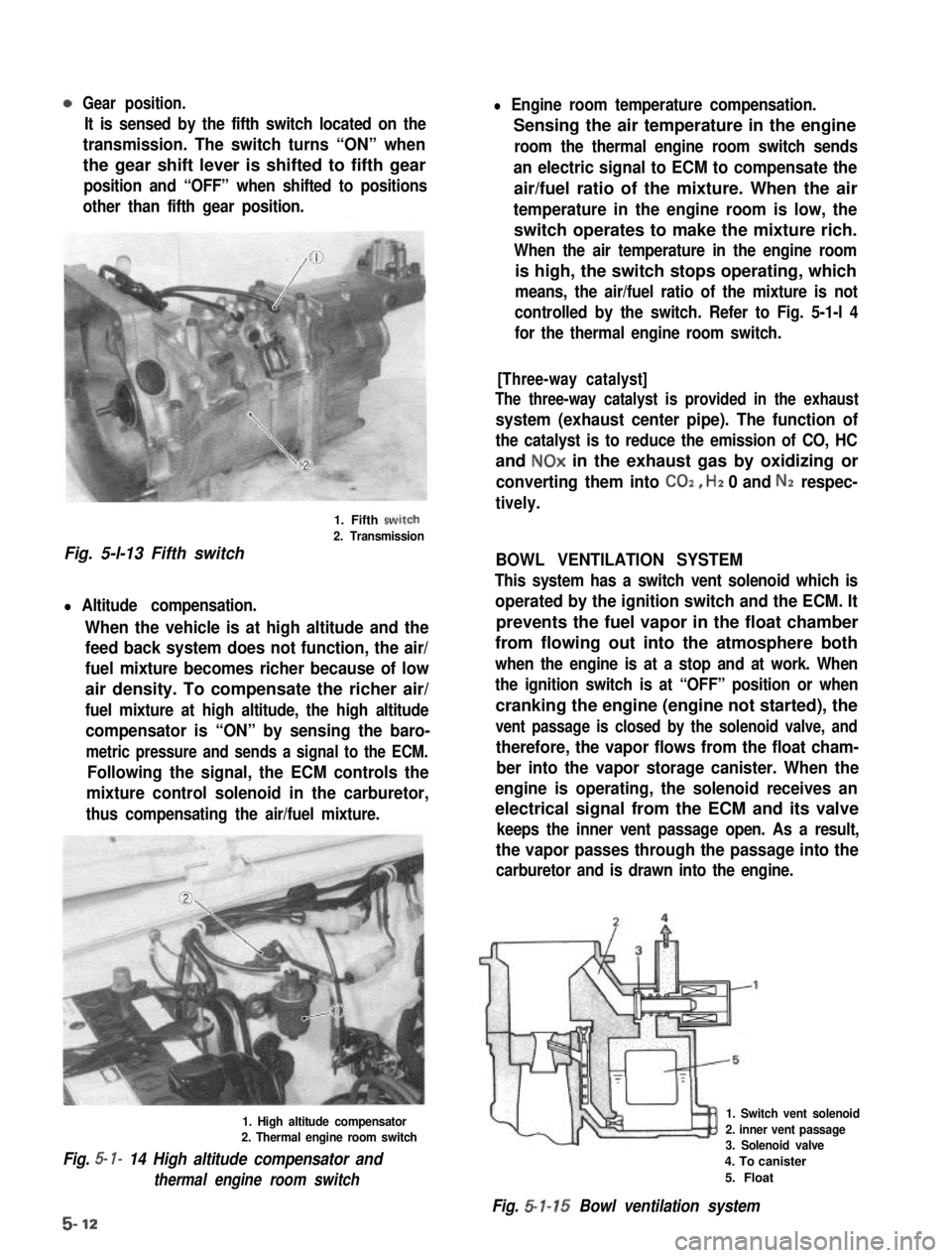
Gear position.
It is sensed by the fifth switch located on the
transmission. The switch turns “ON” when
the gear shift lever is shifted to fifth gear
position and “OFF” when shifted to positions
other than fifth gear position.
1. Fifth swirch
2. Transmission
Fig. 5-l-13 Fifth switch
l Altitude compensation.
When the vehicle is at high altitude and the
feed back system does not function, the air/
fuel mixture becomes richer because of low
air density. To compensate the richer air/
fuel mixture at high altitude, the high altitude
compensator is “ON” by sensing the baro-
metric pressure and sends a signal to the ECM.
Following the signal, the ECM controls the
mixture control solenoid in the carburetor,
thus compensating the air/fuel mixture.
1. High altitude compensator2. Thermal engine room switch
Fig. 5- I- 14 High altitude compensator and
thermal engine room switch
l Engine room temperature compensation.
Sensing the air temperature in the engine
room the thermal engine room switch sends
an electric signal to ECM to compensate the
air/fuel ratio of the mixture. When the air
temperature in the engine room is low, the
switch operates to make the mixture rich.
When the air temperature in the engine room
is high, the switch stops operating, which
means, the air/fuel ratio of the mixture is not
controlled by the switch. Refer to Fig. 5-1-l 4
for the thermal engine room switch.
[Three-way catalyst]
The three-way catalyst is provided in the exhaust
system (exhaust center pipe). The function of
the catalyst is to reduce the emission of CO, HC
and NOx in the exhaust gas by oxidizing or
converting them into CO2, Hz 0 and Nz respec-
tively.
BOWL VENTILATION SYSTEM
This system has a switch vent solenoid which is
operated by the ignition switch and the ECM. It
prevents the fuel vapor in the float chamber
from flowing out into the atmosphere both
when the engine is at a stop and at work. When
the ignition switch is at “OFF” position or when
cranking the engine (engine not started), the
vent passage is closed by the solenoid valve, and
therefore, the vapor flows from the float cham-
ber into the vapor storage canister. When the
engine is operating, the solenoid receives an
electrical signal from the ECM and its valve
keeps the inner vent passage open. As a result,
the vapor passes through the passage into the
carburetor and is drawn into the engine.
1. Switch vent solenoid
2. inner vent passage3. Solenoid valve
4. To canister
5. Float
Fig. 5-l-15 Bowl ventilation system
5-12
Page 265 of 962

13-3. DISMOUNTINGIn Passenger Compartment
1) Loosen 4 bolts fastening gear shift lever boot
No. 2 and move boot upward.
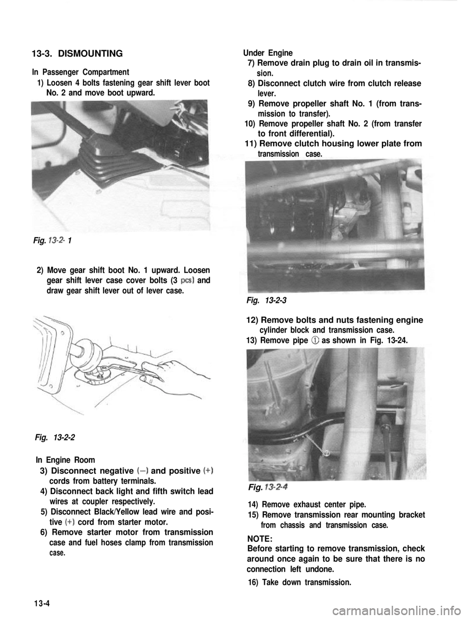
Fig.
13-2- 1 Under Engine
7) Remove drain plug to drain oil in transmis-
sion.
8) Disconnect clutch wire from clutch release
lever.
9) Remove propeller shaft No. 1 (from trans-
mission to transfer).
10) Remove propeller shaft No. 2 (from transfer
to front differential).
11) Remove clutch housing lower plate from
transmission case.
2) Move gear shift boot No. 1 upward. Loosen
gear shift lever case cover bolts (3
PCS) and
draw gear shift lever out of lever case.
Fig. 13-2-3
Fig. 13-2-2 In Engine Room
3) Disconnect negative (-) and positive (+)
cords from battery terminals.
4) Disconnect back light and fifth switch lead
wires at coupler respectively.
5) Disconnect Black/Yellow lead wire and posi- tive
(+) cord from starter motor.
6) Remove starter motor from transmission
case and fuel hoses clamp from transmission
case.
12) Remove bolts and nuts fastening engine
cylinder block and transmission case.
13) Remove pipe (iJ as shown in Fig. 13-24.
Fig. 13-2-4
14) Remove exhaust center pipe.
15) Remove transmission rear mounting bracket
from chassis and transmission case.
NOTE:
Before starting to remove transmission, check
around once again to be sure that there is no
connection left undone.
16) Take down transmission.
13-4
Page 276 of 962

Gear Shift Shafts
Check the part of shaft as indicated in below
figure for uneven wear. Replace shaft if uneven
wear is noted.
Fig. 13-40
Extension Case Bush
Check bush press-fitted in extension case for
wear by measuring radial clearance between
bush bore and sliding yoke. If sliding yoke
rattles in bush because of advanced wear it will
cause propeller shaft to rattle. For this reason,
an extension case found to allow its sliding
yoke to rattle in excess of service limit must be
replaced; replacement of bush alone is not
permissible.
Rattle of
sliding yoke
c
in extension
case bush Standard
1 Service limit
0.025
- 0.089 mm 0.2 mm
(0.0010
- 0.0035 in.) (0.0078 in.)
III
13-6. IMPORTANT STEPS IN
INSTALLATION
NOTE:
l Before installation, wash each part and apply
specified gear oil to sliding faces of bearing
and gear.
l Use new circlips on shaft for reinstallation.
Don’t reuse used circlips.
l Tighten each fastening bolt and nut according
to specified torque data listed on the last
page of this section.
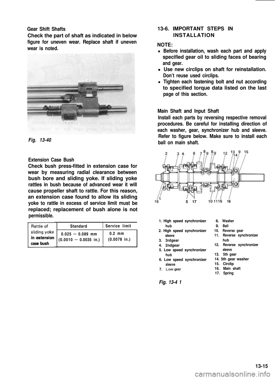
Main Shaft and Input Shaft:,
Install each parts by reversing respective removal
procedures. Be careful for installing direction of
each washer, gear, synchronizer hub and sleeve.
Refer to figure below. Make sure to install each
ball on main shaft.
5 17la 1.11616
1. High speed synchronizer
hub2. High speed synchronizer
sleeve
3.3rdgear
4.2ndgear
5. Low speed synchronizer
hub6. Low speed synchronizer
sleeve
7.Lowgear
6.Washer
9.Ball10.Reverse gear11. Reverse synchronizer
hub
12.Reverse synchronizer
sleeve13.5th gear14. 5th gear washer
15. Circlip
16.
Main shaft17.Spring
Fig. 13-4 1
13-15
Page 284 of 962
4) Uniformly apply sealant (SUZUKI BOND
NO. 1215, 99000-31110) to mating surface
of lower case.
Extension Case
1) Check to ensure that knock pins @ are
fitted.
Fig. 13-77Fig. 13-79
5) Install upper case to lower case by matching
3 shift forks with 3 grooves in synchronizer
sleeve on main shaft respectively.
Fig. 13-78 CiJ Shift forks
2)Apply grease (SUZUKI SUPER GREASE
A 99000-25010) to oil seal lip.
3) Clean surface of extension case to mate
with transmission case and uniformly apply
sealant (SUZUKI BOND No. 1215, 99000-
31110).
Fig. 13-806) Tighten case bolts to specification.
Tightening torque N.mkg-mlb-ftfor transmissioncase bolts18-281.8-2.813.5-20.0
4) Make sure that 3 shift shafts are in neutral
position as shown in Fig. 13-23.
5) Install extension case to transmission case.
6) Tighten case bolts to specification.
Tightening torque N.mkg-mlb-ftfor extension casebolts18-281.8-2.813.5-20.0
13-23
Page 338 of 962
BARFIELD JOINT CONSTRUCTION AND OPERATION
The major parts of the Barfield joint are the outer race (integral with wheel spindle, to which the wheel
disc is splined), inner race (splined to the live axle shaft), six steel balls disposed between the two races,
and cage (holding the steel balls in a single row lying in a plane).
Spindle shaft
IInner raceSteel ball
The balls are fitted in two groups of raceways; one group is on the outer race and the other group on the
inner race. Each ball is in its own raceways as if it were locked between the two races in the direction of
rotation. The outer race with its wheel spindle is capable of angling and, when it so angles with respect to
the axis of axle shaft, the row of steel balls angles just half as much, that is, the plane including this row
tilts by an angle equal to one-half of the spindle angle. This relationship is illustrated in Fig. 17-1-4.
CageOuter race
Steel ball
17-4
Fig. 17-1-3
Fig. 17-1-4
Page 348 of 962
Stabilizer
Stabilizer bolt & lock washerI
18-28N.m
1.8 - 2.8 kg-m13.5 - 20.0 lb-ft
l Tighten to the following specified torque
in unloaded condition.70 - 90 N.m
l
7.0 - 9.0 kg-m
51 .O - 65.0 lb-ftInstall lock washer in body outer side.
1 Stabilizer nut
qPaint
Tighten tothe following specified
torque in unloaded condition.22-35 N.m
2.2-3.5 kg-m
16.0-25.0 lb-ft
Stabilizer mount bush
View A
Install stabilizer mount bushes (right & left) by aligningthem with painted positions on stabilizer respectively.
Fig. 17-1-35
17-14
Page 368 of 962
18-4. REMOVAL
NOTE:
When removing the column assembly from the
car, special care must be taken in handling it
Use of a steering wheel puller other than the
steering wheel remover recommended in this
manual or a sharp blow on the end of the
steering shaft, leaning on the assembly, or
dropping the assembly is prohibited. Any of
such actions could shear the plastic shear pins
which maintain column length especially.
Steering Hand Wheel
1) Disconnect negative battery cable.
2) Pull horn button to remove.
Fig. 18-3
3) After loosening steering shaft nut, remove
steering wheel by using special tool.
Fig. 18-4 @ Special tool (Steering wheel
remover 09944-36010)
Steering Column
1) After removing steering handwheel according
to the foregoing step, remove steering covers
(lower & upper).
NOTE:
After removing instrument lower panel, loosen
2 screws and 4 nuts securing steering column to
remove upper cover.
Fig. 18-5
18-6
Page 379 of 962

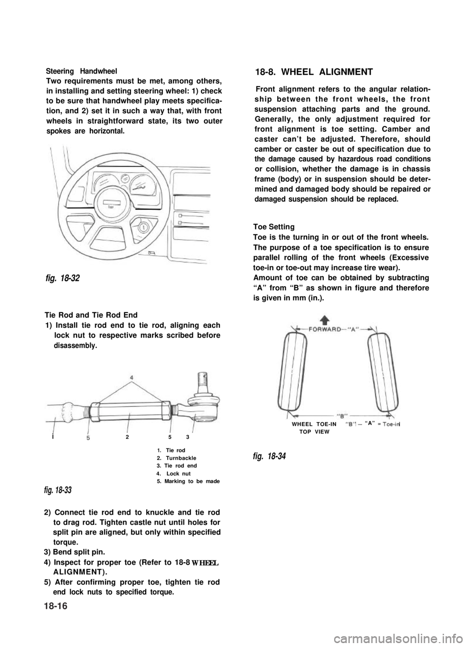
Steering Handwheel
Two requirements must be met, among others,
in installing and setting steering wheel: 1) check
to be sure that handwheel play meets specifica-
tion, and 2) set it in such a way that, with front
wheels in straightforward state, its two outer
spokes are horizontal.
fig. 18-32
Tie Rod and Tie Rod End
1) Install tie rod end to tie rod, aligning each
lock nut to respective marks scribed before
disassembly.
i25 3
1.Tie rod
2.Turnbackle3. Tie rod end
4.Lock nut5. Marking to be made
fig. 18-33
2) Connect tie rod end to knuckle and tie rod
to drag rod. Tighten castle nut until holes for
split pin are aligned, but only within specified
torque.
3) Bend split pin.
4) Inspect for proper toe (Refer to 18-8 WHEEL
ALIGNMENT).
5) After confirming proper toe, tighten tie rod
end lock nuts to specified torque.
18-8. WHEEL ALIGNMENT
Front alignment refers to the angular relation-
ship between the front wheels, the front
suspension attaching parts and the ground.
Generally, the only adjustment required for
front alignment is toe setting. Camber and
caster can’t be adjusted. Therefore, should
camber or caster be out of specification due to
the damage caused by hazardous road conditions
or collision, whether the damage is in chassis
frame (body) or in suspension should be deter-
mined and damaged body should be repaired or
damaged suspension should be replaced.
Toe Setting
Toe is the turning in or out of the front wheels.
The purpose of a toe specification is to ensure
parallel rolling of the front wheels (Excessive
toe-in or toe-out may increase tire wear).
Amount of toe can be obtained by subtracting
“A” from “B” as shown in figure and therefore
is given in mm (in.).
WHEEL TOE-IN“6” - “A” = Toe-in
TOP VIEW
fig. 18-34
18-16