1987 SUZUKI GRAND VITARA fuel type
[x] Cancel search: fuel typePage 61 of 962
3) Cylinder Head and Valve Train
The cylinder head is made of cast aluminum alloy and has four combustion chambers arranged in-line.
Each combustion chamber has an intake and an exhaust ports.
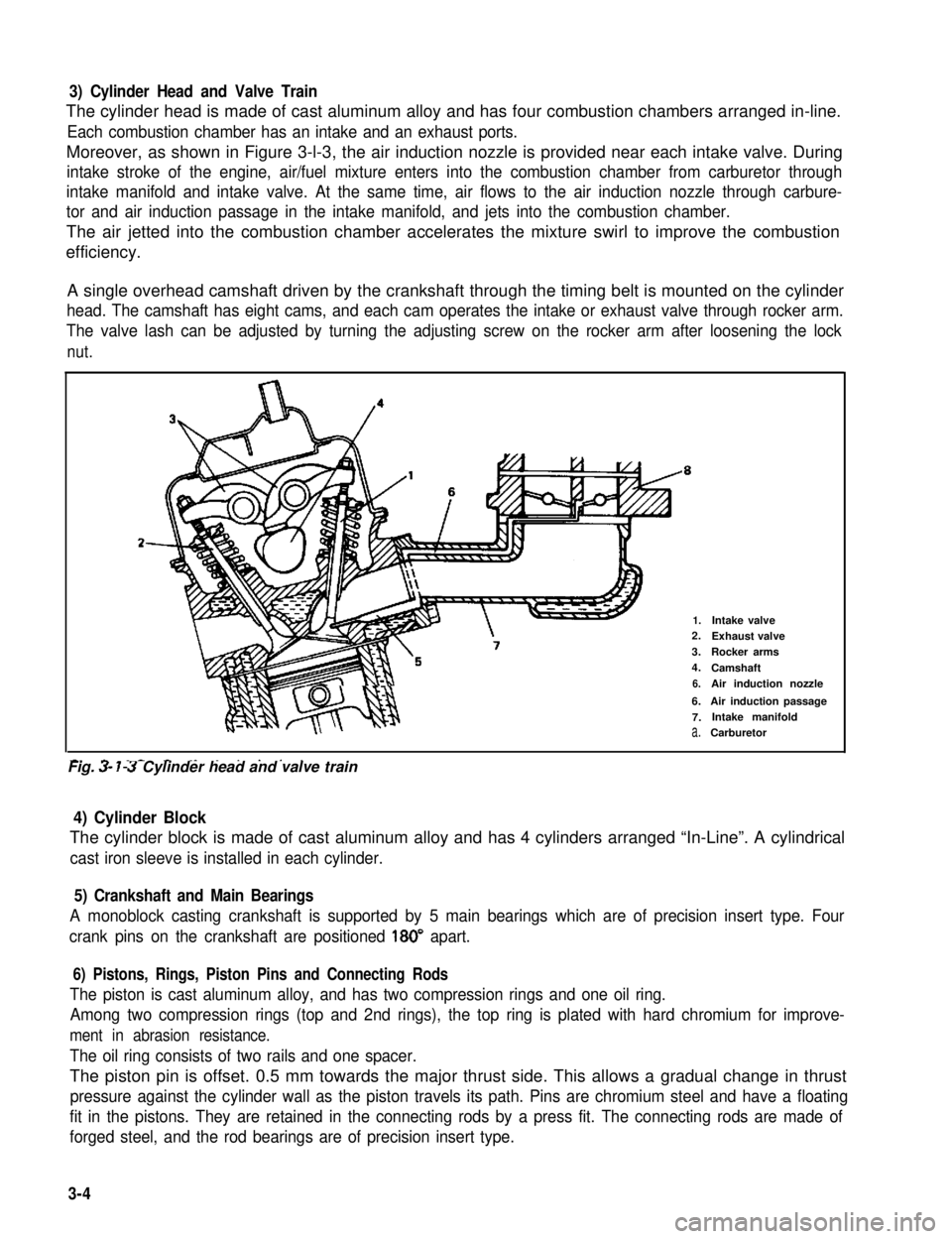
Moreover, as shown in Figure 3-l-3, the air induction nozzle is provided near each intake valve. During
intake stroke of the engine, air/fuel mixture enters into the combustion chamber from carburetor through
intake manifold and intake valve. At the same time, air flows to the air induction nozzle through carbure-
tor and air induction passage in the intake manifold, and jets into the combustion chamber.
The air jetted into the combustion chamber accelerates the mixture swirl to improve the combustion
efficiency.
A single overhead camshaft driven by the crankshaft through the timing belt is mounted on the cylinder
head. The camshaft has eight cams, and each cam operates the intake or exhaust valve through rocker arm.
The valve lash can be adjusted by turning the adjusting screw on the rocker arm after loosening the lock
nut.
2-
1.Intake valve2.Exhaust valve
3.Rocker arms
4.Camshaft
6.Air induction nozzle
6.Air induction passage
7.Intake manifold
a.Carburetor
-. - _- - ._ . . . . .Fig. 3- 7-3 Cylinder head and valve train
4) Cylinder Block
The cylinder block is made of cast aluminum alloy and has 4 cylinders arranged “In-Line”. A cylindrical
cast iron sleeve is installed in each cylinder.
5) Crankshaft and Main Bearings
A monoblock casting crankshaft is supported by 5 main bearings which are of precision insert type. Four
crank pins on the crankshaft are positioned 180” apart.
6) Pistons, Rings, Piston Pins and Connecting Rods
The piston is cast aluminum alloy, and has two compression rings and one oil ring.
Among two compression rings (top and 2nd rings), the top ring is plated with hard chromium for improve-
ment in abrasion resistance.
The oil ring consists of two rails and one spacer.
The piston pin is offset. 0.5 mm towards the major thrust side. This allows a gradual change in thrust
pressure against the cylinder wall as the piston travels its path. Pins are chromium steel and have a floating
fit in the pistons. They are retained in the connecting rods by a press fit. The connecting rods are made of
forged steel, and the rod bearings are of precision insert type.
3-4
Page 117 of 962
4-1. CARBURETOR
GENERAL DESCRIPTION
General
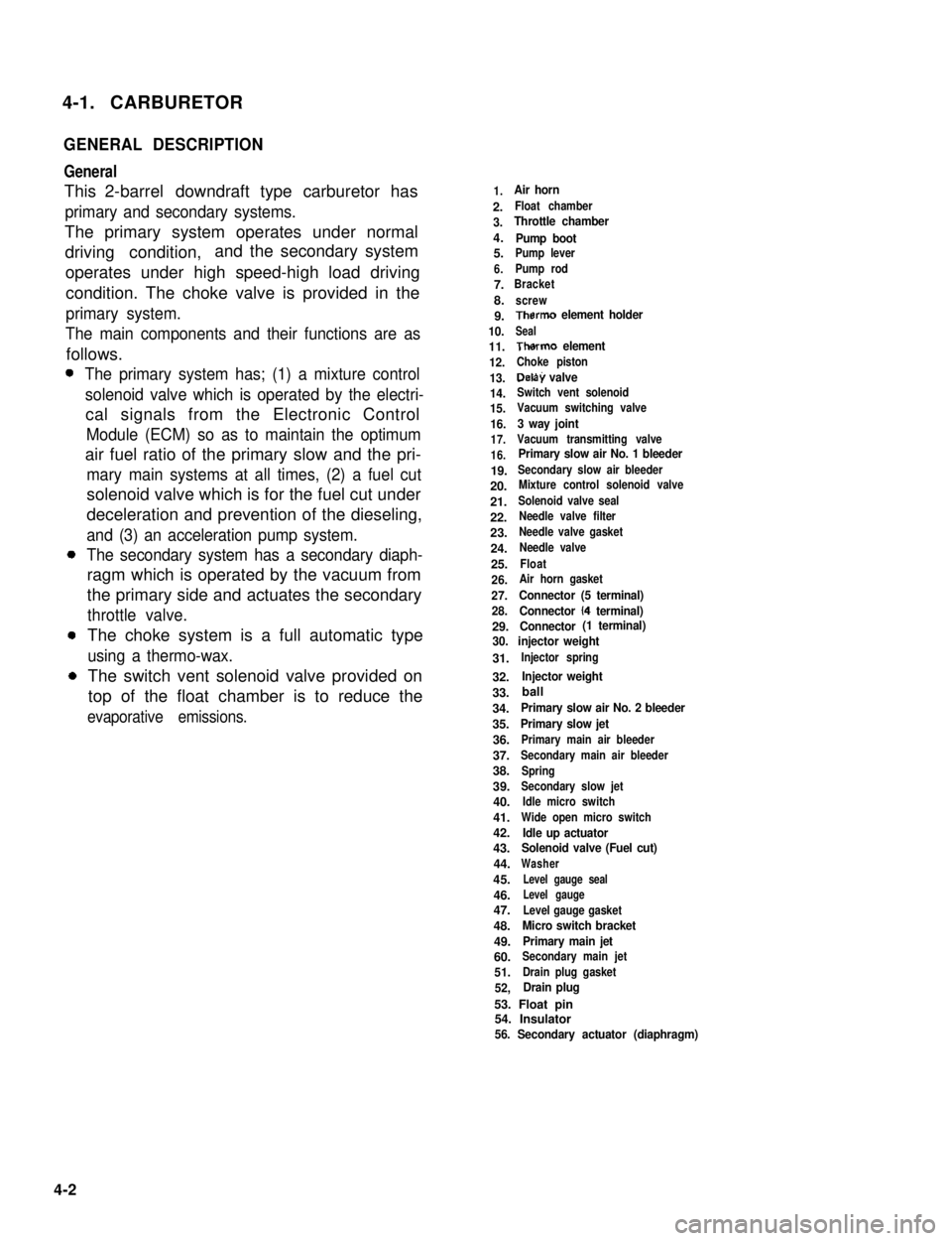
This 2-barrel downdraft type carburetor has
primary and secondary systems.
The primary system operates under normal
driving condition,and the secondary system
operates under high speed-high load driving
condition. The choke valve is provided in the
primary system.
The main components and their functions are as
follows.
The primary system has; (1) a mixture control
solenoid valve which is operated by the electri-
cal signals from the Electronic Control
Module (ECM) so as to maintain the optimum
air fuel ratio of the primary slow and the pri-
mary main systems at all times, (2) a fuel cut
solenoid valve which is for the fuel cut under
deceleration and prevention of the dieseling,
and (3) an acceleration pump system.
The secondary system has a secondary diaph-
ragm which is operated by the vacuum from
the primary side and actuates the secondary
throttle valve.
The choke system is a full automatic type
using a thermo-wax.
The switch vent solenoid valve provided on
top of the float chamber is to reduce the
evaporative emissions.
1.Air horn
2.Float chamber
3.Throttle chamber
4.Pump boot5.Pump lever
6.Pump rod
7.Bracket
8.screw
9.Therm0 element holder
10.Seal
11.Therm0 element
12.Choke piston
13.Delay valve
14.Switch vent solenoid
15.Vacuum switching valve
16.3 way joint
17.Vacuum transmitting valve
16.Primary slow air No. 1 bleeder
19.Secondary slow air bleeder
20.Mixture control solenoid valve
21.Solenoid valve seal
22.Needle valve filter
23.Needle valve gasket
24.Needle valve
25.Float
26.Air horn gasket
27.Connector (5 terminal)
28.Connector (4 terminal)
29.Connector (1 terminal)
30. injector weight
31.Injector spring
32.Injector weight
33.
34.Primary slow air No. 2 bleeder
35.Primary slow jet
36.Primary main air bleeder
37.Secondary main air bleeder
38.Spring
39.Secondary slow jet
40.Idle micro switch
41.Wide open micro switch
42.Idle up actuator43.Solenoid valve (Fuel cut)
44.Washer
45.Level gauge seal
46.Level gauge
47.Level gauge gasket
48.Micro switch bracket
49.Primary main jet
60.Secondary main jet
51.Drain plug gasket
52,Drain plug
53. Float pin54. Insulator56. Secondary actuator (diaphragm)
4-2
ball
Page 144 of 962
4-2. AIR CLEANER
GENERAL DESCRIPTION
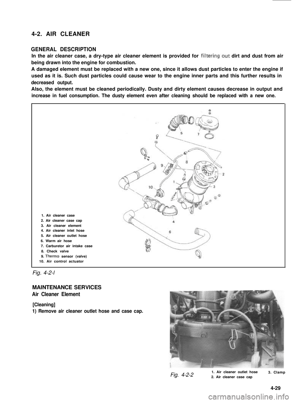
In the air cleaner case, a dry-type air cleaner element is provided for filtering.out dirt and dust from air
being drawn into the engine for combustion.
A damaged element must be replaced with a new one, since it allows dust particles to enter the engine if
used as it is. Such dust particles could cause wear to the engine inner parts and this further results in
decreased output.
Also, the element must be cleaned periodically. Dusty and dirty element causes decrease in output and
increase in fuel consumption. The dusty element even after cleaning should be replaced with a new one.
Fig. 4-2-l
1. Air cleaner case
2. Air cleaner case cap
3. Air cleaner element4. Air cleaner inlet hose
5. Air cleaner outlet hose
6. Warm air hose
7. Carburetor air intake case
8. Check valve
9. Therm0 sensor (valve)10. Air control actuator
MAINTENANCE SERVICES
Air Cleaner Element
[Cleaning]
1) Remove air cleaner outlet hose and case cap.
Fig. 4-2-21. Air cleaner outlet hose2. Air cleaner case cap3. Clamp
4-29
Page 147 of 962
Fuel Pulp
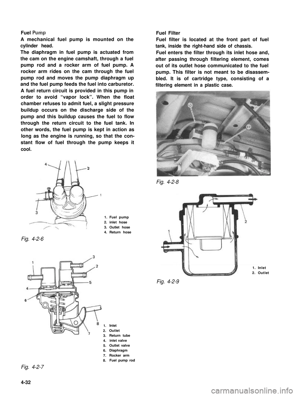
A mechanical fuel pump is mounted on the
cylinder head.
The diaphragm in fuel pump is actuated from
the cam on the engine camshaft, through a fuel
pump rod and a rocker arm of fuel pump. A
rocker arm rides on the cam through the fuel
pump rod and moves the pump diaphragm up
and the fuel pump feeds the fuel into carburetor.
A fuel return circuit is provided in this pump in
order to avoid “vapor lock”. When the float
chamber refuses to admit fuel, a slight pressure
buildup occurs on the discharge side of the
pump and this buildup causes the fuel to flow
through the return circuit to the fuel tank. In
other words, the fuel pump is kept in action as
long as the engine is running, so that the con-
stant flow of fuel through the pump keeps it
cool.
2
Fig. 4-2-8
Fig. 4-2-6
Fuel Filter
Fuel filter is located at the front part of fuel
tank, inside the right-hand side of chassis.
Fuel enters the filter through its inlet hose and,
after passing through filtering element, comes
out of its outlet hose communicated to the fuel
pump. This filter is not meant to be disassem-
bled. It is of cartridge type, consisting of a
filtering element in a plastic case.
1
1. Fuel pump
2. inlet hose
3. Outlet hose4. Return hose
6
1. Inlet
2. Outlet
Fig. 4-2-9
1.Inlet
2.Outlet
3.Return tube
4.inlet valve
5.Outlet valve
6.Diaphragm
7.Rocker arm
8.Fuel pump rod
Fig. 4-2-7
4-32
Page 148 of 962
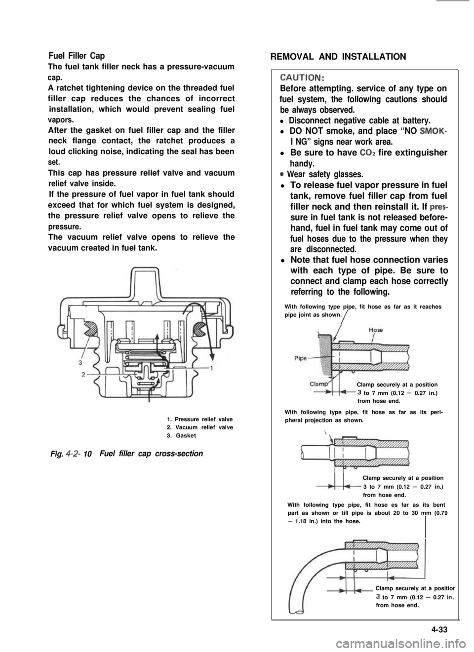
Fuel Filler Cap
The fuel tank filler neck has a pressure-vacuum
cap.
A ratchet tightening device on the threaded fuel
filler cap reduces the chances of incorrect
installation, which would prevent sealing fuel
vapors.
After the gasket on fuel filler cap and the filler
neck flange contact, the ratchet produces a
loud clicking noise, indicating the seal has been
set.
This cap has pressure relief valve and vacuum
relief valve inside.
If the pressure of fuel vapor in fuel tank should
exceed that for which fuel system is designed,
the pressure relief valve opens to relieve the
pressure.
The vacuum relief valve opens to relieve the
vacuum created in fuel tank.
1. Pressure relief valve2. Vacuum relief valve
3. Gasket
Fig. 4-2- 10Fuel filler cap cross-section
REMOVAL AND INSTALLATION
CALJTION:
Before attempting. service of any type on
fuel system, the following cautions should
be always observed.
l Disconnect negative cable at battery.
l DO NOT smoke, and place “NO SMOK-
I NG” signs near work area.
l Be sure to have COZ fire extinguisher
handy.
0 Wear safety glasses.
l To release fuel vapor pressure in fuel
tank, remove fuel filler cap from fuel
filler neck and then reinstall it. If prec
sure in fuel tank is not released before-
hand, fuel in fuel tank may come out of
fuel hoses due to the pressure when they
are disconnected.
l Note that fuel hose connection varies
with each type of pipe. Be sure to
connect and clamp each hose correctly
referring to the following.
With following type pipe, fit hose as far as it reachespipe joint as shown./
Clamp securely at a position
3 to 7 mm (0.12 - 0.27 in.)from hose end.
With following type pipe, fit hose as far as its peri-pheral projection as shown.
\
Clamp securely at a position
3 to 7 mm (0.12 - 0.27 in.)
from hose end.
With following type pipe, fit hose es far as its bentpart as shown or till pipe is about 20 to 30 mm (0.79
- 1.18 in.) into the hose.
Clamp securely at a positior
3 to 7 mm (0.12 - 0.27 in.:from hose end.
4-33
Page 472 of 962
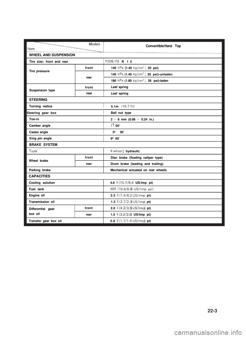
Convertible/Hard Top
WHEEL AND SUSPENSIONI
Tire size: front and rear1 P205/70 R15I
Tire pressurefront
rear
Suspension typefront
rear
140 kPa (1.40 kg/cm’, 20 psi)
140 kPa (1.40 kg/cm’, 20 psi)-unladen
180 kPa (1.80 kg/cm*, 26 psi)-laden
Leaf spring
Leaf spring
STEERING
Turning radius1 5.1 m (16.7ft)
1 Steering gear box1Ball nut typeI
Toe-in
Camber angle
Caster angle
King pin angle
BRAKE SYSTEM
Type
Wheel brake
Parking brake
CAPACITIES
Cooling solution
Fuel tank
2 - 6 mm (0.08 - 0.24 in.)
lo 00’
) 3º 30’I
front
rear
9º 00’
4-wheel, hydraulic
Disc brake (floating caliper type)
Drum brake (leading and trailing)
Mechanical actuated on rear wheels
4.8 Q (10.1/8.4 US/Imp pt)
4OQ (10.6/8.8 US/Imp cral)
Engine oil
Transmission oil
Differential gear
box oil
Transfer gear box oil
front
rear
3.5 II (7.4/6.2 US/Imp pt)
1.3 II (2.7/2.3 US/Imp pt)
2.0 Q (4.2/3.5 US/Imp pt)
1.5 II (3.2/2.6 US/Imp pt)
0.8 !? (1.7/l .4 US/Imp pt)
22-3