1987 SUZUKI GRAND VITARA lock
[x] Cancel search: lockPage 3 of 962
SECTION 0
GENERAL, SPECIAL TOOLS AND
SERVICE MATERIALS
CONTENTS
0-1. IDENTIFICATION NUMBER . . . . . . . . . . . . . . . . . . . . . . . . . . . . . . . . . O-1
0-2. STANDARD SHOP PRACTICES . . . . . . . . . . . . . . . . . . . . . . . . . . . . . . . O-2
0-3.SPECIAL TOOLS.. . . . . . . . . . . . 1.. . . . . . . . . . . . . . . . . . . . . . . . . . . . .
0-4.REQUIRED SERVICE MATERIALS . . . . . . . . . . . . . . . . . . . . . s . . . . . O-9
METRIC INFORMATION . . . . . . . . . . . . . . . . . . . . . , . . . . . . . . . . . . . O-12
O-l. IDENTIFICATION NUMBER
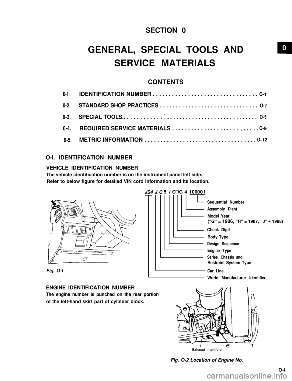
VEHICLE IDENTIFICATION NUMBER
The vehicle identification number is on the instrument panel left side.
Refer to below figure for detailed VIN cord information and its location.
5 1 C G 4 100001
Sequential Number
Assembly Plant
Model Year
(“G” = 1986, “H” = 1987, “J” = 1988)
Check Digit
Body Type
Design Sequence
Engine Type
Series, Chassis and
Restraint System Type
Car Line
World Manufacturer Identifier
Fig. O-l
ENGINE IDENTIFICATION NUMBER
The engine number is punched on the rear portion
of the left-hand skirt part of cylinder block.
Exhaust manifold
Fig. O-2 Location of Engine No.
O-l
JS4 J C
0-5.
O- 5
0
Page 5 of 962
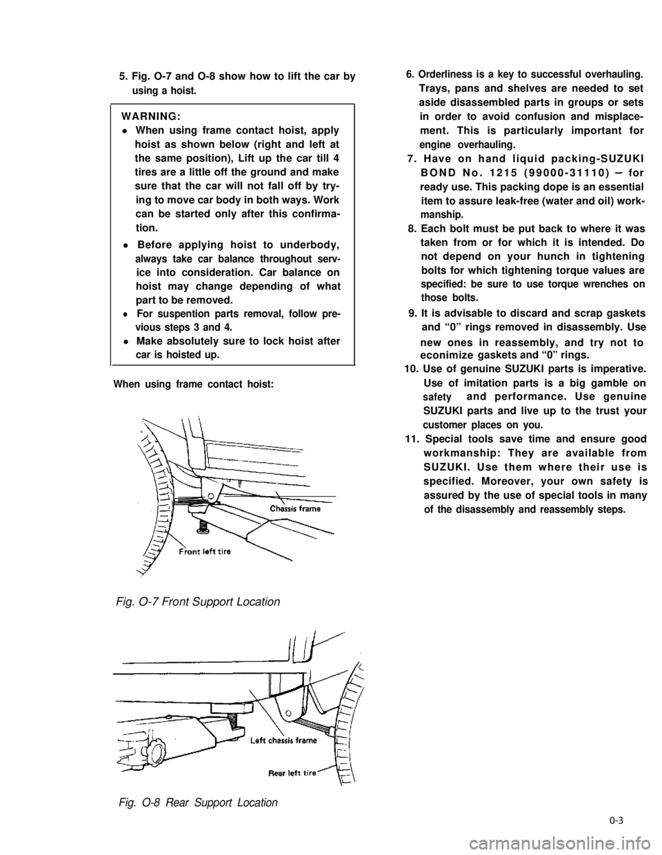
5. Fig. O-7 and O-8 show how to lift the car by
using a hoist.
WARNING:
l When using frame contact hoist, apply
hoist as shown below (right and left at
the same position), Lift up the car till 4
tires are a little off the ground and make
sure that the car will not fall off by try-
ing to move car body in both ways. Work
can be started only after this confirma-
tion.
l Before applying hoist to underbody,
always take car balance throughout serv-
ice into consideration. Car balance on
hoist may change depending of what
part to be removed.
lFor suspention parts removal, follow pre-
vious steps 3 and 4.
l Make absolutely sure to lock hoist after
car is hoisted up.
When using frame contact hoist:
6. Orderliness is a key to successful overhauling.
Trays, pans and shelves are needed to set
aside disassembled parts in groups or sets
in order to avoid confusion and misplace-
ment. This is particularly important for
engine overhauling.
7. Have on hand liquid packing-SUZUKI
BOND No. 1215 (99000-31110) - for
ready use. This packing dope is an essential
item to assure leak-free (water and oil) work-
manship.
8. Each bolt must be put back to where it was
taken from or for which it is intended. Do
not depend on your hunch in tightening
bolts for which tightening torque values are
specified: be sure to use torque wrenches on
those bolts.
9. It is advisable to discard and scrap gaskets
and “0” rings removed in disassembly. Use
new ones in reassembly, and try not to
econimize gaskets and “0” rings.
10. Use of genuine SUZUKI parts is imperative.
Use of imitation parts is a big gamble on
safetyand performance. Use genuine
SUZUKI parts and live up to the trust your
customer places on you.
11. Special tools save time and ensure good
workmanship: They are available from
SUZUKI. Use them where their use is
specified. Moreover, your own safety is
assured by the use of special tools in many
of the disassembly and reassembly steps.
Fig. O-7 Front Support Location
Fig. O-8 Rear Support Location
0-3
Page 22 of 962
5) Remove timing belt outside cover. Inspect
the belt for damage or wear. When any
damage or wear is found on the belt, replace
it.
If belt replacement is necessary, be sure to
install the belt properly.
6) Remove cylinder head cover and loosen all
valve adjusting screws all the way to permit
free rotation of camshaft.
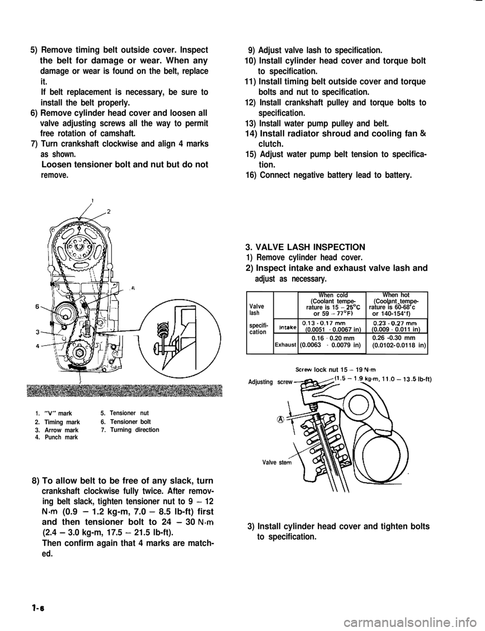
7) Turn crankshaft clockwise and align 4 marks
as shown.
Loosen tensioner bolt and nut but do not
remove.
9) Adjust valve lash to specification.
10) Install cylinder head cover and torque bolt
to specification.
11) Install timing belt outside cover and torque
bolts and nut to specification.
12) Install crankshaft pulley and torque bolts to
specification.
13) Install water pump pulley and belt.
14) Install radiator shroud and cooling fan &
clutch.
15) Adjust water pump belt tension to specifica-
tion.
16) Connect negative battery lead to battery.
3. VALVE LASH INSPECTION
1) Remove cylinder head cover.
2) Inspect intake and exhaust valve lash and
adjust as necessary.
1.“V” mark5.Tensioner nut
2.Timing mark6.Tensioner bolt
3.Arrow mark7.Turning direction4.Punch mark
8) To allow belt to be free of any slack, turn
crankshaft clockwise fully twice. After remov-
ing belt slack, tighten tensioner nut to 9 - 12
N-m (0.9- 1.2 kg-m, 7.0 - 8.5 lb-ft) first
and then tensioner bolt to 24 - 30 N-m
(2.4 - 3.0 kg-m, 17.5 - 21.5 lb-ft).
Then confirm again that 4 marks are match-
ed.
Valvelash specifi-cation
When coldWhen hot(Coolant tempe-(Coolant tempe---rature is 15 - 25’Crature is 60-68 c or 59 - or 140-154 f)
0.13-0.17mm 0.23-0.27mmIntake(0.0051- 0.0067 in)(0.009 - 0.011 in)
0.16-0.20 mm0.26 -0.30 mm(0.0102- Exhaust (0.0063 - 0.0079 in) 0.0118 in)
Screw lock nut 15 - 19 N.m
Adjusting screw
Valve ste
.5 lb-ft)
3) Install cylinder head cover and tighten bolts
to specification.
l-6
Page 31 of 962
1) Replace fuel hoses (pipe to fuel pump, pipe to
fuel filter and breather hose) in fuel feed and
return lines with new ones.
2) Remove fuel tank.
3) Replace return hose (tank to return pipe)
with new one.
4) Clamp hoses securely.
5) Install fuel tank referring to p. 4-35.
6) After installation, start engine and check it
for leaks.
27. IDLE SPEED INSPECTION
NOTE:
Before starting engine, place transmission gear
shift lever in “Neutral”, and set parking brake
and block drive wheels.
1) Warm up engine to normal operating tempe-
rature.
2) Check to ensure that idle speed is within
750 - 850 r/min (rpm).
3) If idle speed is not within specified range,
adjust idle speed. Refer to MAINTENANCE
SERVICE (p. 4-26) for procedures to check
and adjust idle speed.
28. IDLE MIXTURE INSPECTION
1) Warm up engine to normal operating tem-
perature.
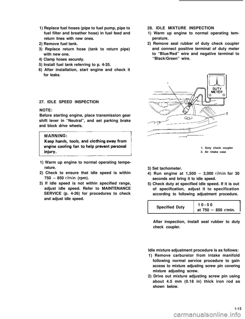
2) Remove seal rubber of duty check coupler
and connect positive terminal of duty meter
to “Blue/Red” wire and negative terminal to
“Black/Green” wire.
1
1. Duty check coupler
2. Air intake case
3) Set tachometer.
4) Run engine at 1,500 - 2,000 r/min for 30
seconds and bring it to idle speed.
5) Check duty at specified idle speed. If it is out
of specification,adjust it to specification
according to following adjustment procedure.
Specified Duty10-50
at 750 - 850 r/min.I
After inspection, install seal rubber to duty
check coupler.
Idle mixture adjustment procedure is as follows:
1) Remove carburetor from intake manifold
following normal service procedure to gain
access to mixture adjusting screw pin covering
mixture adjusting screw.
2) Drive out mixture adjusting screw pin using
about 4.5 mm (0.18 in) thick iron rod as
shown below.
1-15
Page 32 of 962
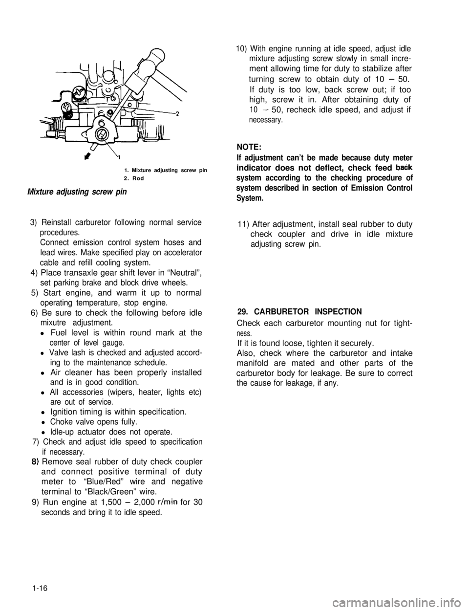
1. Mixture adjusting screw pin
2. Rod
Mixture adjusting screw pin
10) With engine running at idle speed, adjust idle
mixture adjusting screw slowly in small incre-
ment allowing time for duty to stabilize after
turning screw to obtain duty of 10 - 50.
If duty is too low, back screw out; if too
high, screw it in. After obtaining duty of
10- 50, recheck idle speed, and adjust if
necessary.
NOTE:
If adjustment can’t be made because duty meter
indicator does not deflect, check feed baCk
system according to the checking procedure of
system described in section of Emission Control
System.
3) Reinstall carburetor following normal service
procedures.
Connect emission control system hoses and
lead wires. Make specified play on accelerator
cable and refill cooling system.
11) After adjustment, install seal rubber to duty
check coupler and drive in idle mixture
adjusting screw pin.
4) Place transaxle gear shift lever in “Neutral”,
set parking brake and block drive wheels.
5) Start engine, and warm it up to normal
operating temperature, stop engine.
6) Be sure to check the following before idle
mixutre adjustment.
l Fuel level is within round mark at the
center of level gauge.
l Valve lash is checked and adjusted accord-
ing to the maintenance schedule.
l Air cleaner has been properly installed
and is in good condition.
l All accessories (wipers, heater, lights etc)
are out of service.
29. CARBURETOR INSPECTION
Check each carburetor mounting nut for tight-
ness.
If it is found loose, tighten it securely.
Also, check where the carburetor and intake
manifold are mated and other parts of the
carburetor body for leakage. Be sure to correct
the cause for leakage, if any.
l Ignition timing is within specification.
l Choke valve opens fully.
l Idle-up actuator does not operate.
7) Check and adjust idle speed to specification
if necessary.
8) Remove seal rubber of duty check coupler
and connect positive terminal of duty
meter to“Blue/Red” wire and negative
terminal to “Black/Green” wire.
9) Run engine at 1,500 - 2,000 r/min for 30
seconds and bring it to idle speed.
1-16
Page 34 of 962
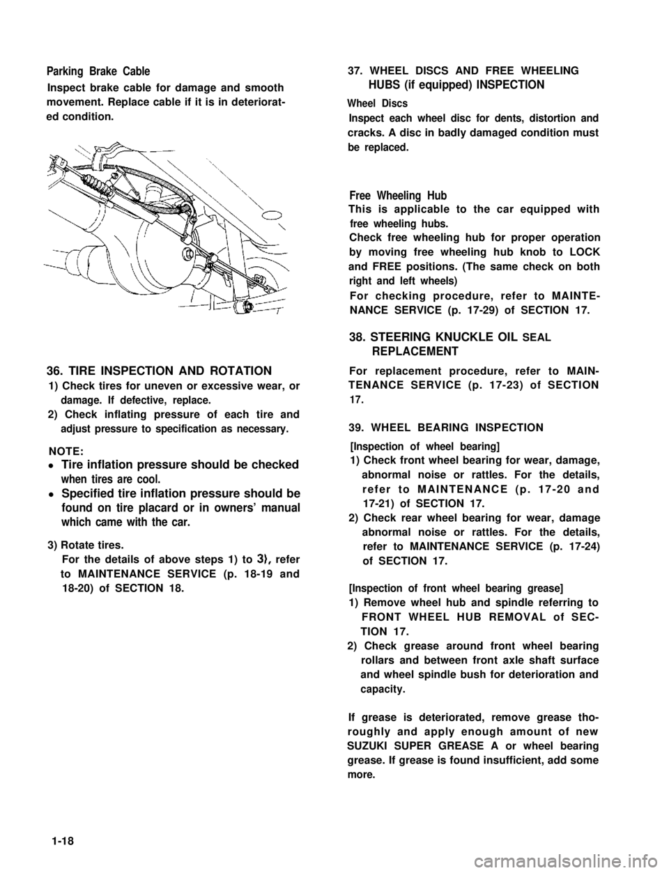
Parking Brake Cable
Inspect brake cable for damage and smooth
movement. Replace cable if it is in deteriorat-
ed condition.
36. TIRE INSPECTION AND ROTATION
1) Check tires for uneven or excessive wear, or
damage. If defective, replace.
2) Check inflating pressure of each tire and
adjust pressure to specification as necessary.
NOTE:
l Tire inflation pressure should be checked
when tires are cool.
l Specified tire inflation pressure should be
found on tire placard or in owners’ manual
which came with the car.
3) Rotate tires.
For the details of above steps 1) to 3), refer
to MAINTENANCE SERVICE (p. 18-19 and
18-20) of SECTION 18.
37. WHEEL DISCS AND FREE WHEELING
HUBS (if equipped) INSPECTION
Wheel Discs
Inspect each wheel disc for dents, distortion and
cracks. A disc in badly damaged condition must
be replaced.
Free Wheeling Hub
This is applicable to the car equipped with
free wheeling hubs.
Check free wheeling hub for proper operation
by moving free wheeling hub knob to LOCK
and FREE positions. (The same check on both
right and left wheels)
For checking procedure, refer to MAINTE-
NANCE SERVICE (p. 17-29) of SECTION 17.
38. STEERING KNUCKLE OIL SEAL
REPLACEMENT
For replacement procedure, refer to MAIN-
TENANCE SERVICE (p. 17-23) of SECTION
17.
39. WHEEL BEARING INSPECTION
[Inspection of wheel bearing]
1) Check front wheel bearing for wear, damage,
abnormal noise or rattles. For the details,
refer to MAINTENANCE (p. 17-20 and
17-21) of SECTION 17.
2) Check rear wheel bearing for wear, damage
abnormal noise or rattles. For the details,
refer to MAINTENANCE SERVICE (p. 17-24)
of SECTION 17.
[Inspection of front wheel bearing grease]
1) Remove wheel hub and spindle referring to
FRONT WHEEL HUB REMOVAL of SEC-
TION 17.
2) Check grease around front wheel bearing
rollars and between front axle shaft surface
and wheel spindle bush for deterioration and
capacity.
If grease is deteriorated, remove grease tho-
roughly and apply enough amount of new
SUZUKI SUPER GREASE A or wheel bearing
grease. If grease is found insufficient, add some
more.
1-18
Page 35 of 962
3) Install spindle, bearings, wheel hub, bearing
nut and brake disc referring to INSTALLA-
TION (p. 17-12) of SECTION 17.
4) Adjust bearing preload and then tighten
bearing lock nut to specification. Refer to
MAINTENANCE (p. 17-21) of SECTION 17.
5) Install drive flange or free wheeling hub (if
equipped), brake caliper with mounting and
wheel referring to INSTALLATION (p. 17-
12) of SECTION 17.
For tightening torque of each bolt and nut,
refer to torque table (p. 17-26) of SECTION
17.
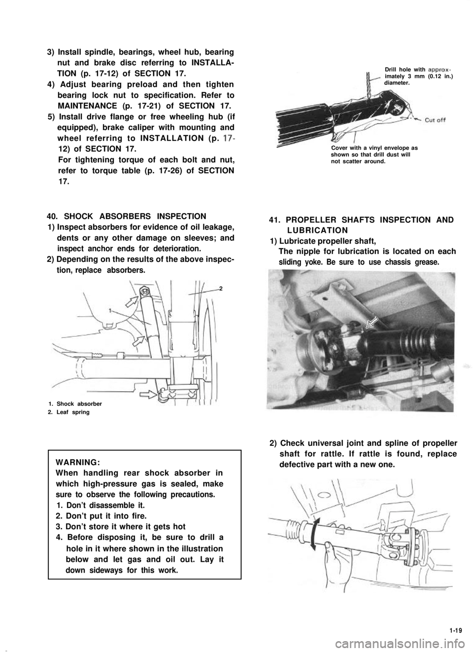
40. SHOCK ABSORBERS INSPECTION
1) Inspect absorbers for evidence of oil leakage,
dents or any other damage on sleeves; and
inspect anchor ends for deterioration.
2) Depending on the results of the above inspec-
tion, replace absorbers.
2
1. Shock absorber
2. Leaf spring
WARNING:
When handling rear shock absorber in
which high-pressure gas is sealed, make
sure to observe the following precautions.
1. Don’t disassemble it.
2. Don’t put it into fire.
3. Don’t store it where it gets hot
4. Before disposing it, be sure to drill a
hole in it where shown in the illustration
below and let gas and oil out. Lay it
down sideways for this work.
Drill hole with approx-imately 3 mm (0.12 in.)diameter.
Cover with a vinyl envelope asshown so that drill dust willnot scatter around.
41. PROPELLER SHAFTS INSPECTION AND
LUBRICATION
1) Lubricate propeller shaft,
The nipple for lubrication is located on each
sliding yoke. Be sure to use chassis grease.
2) Check universal joint and spline of propeller
shaft for rattle. If rattle is found, replace
defective part with a new one.
1-19
Page 60 of 962
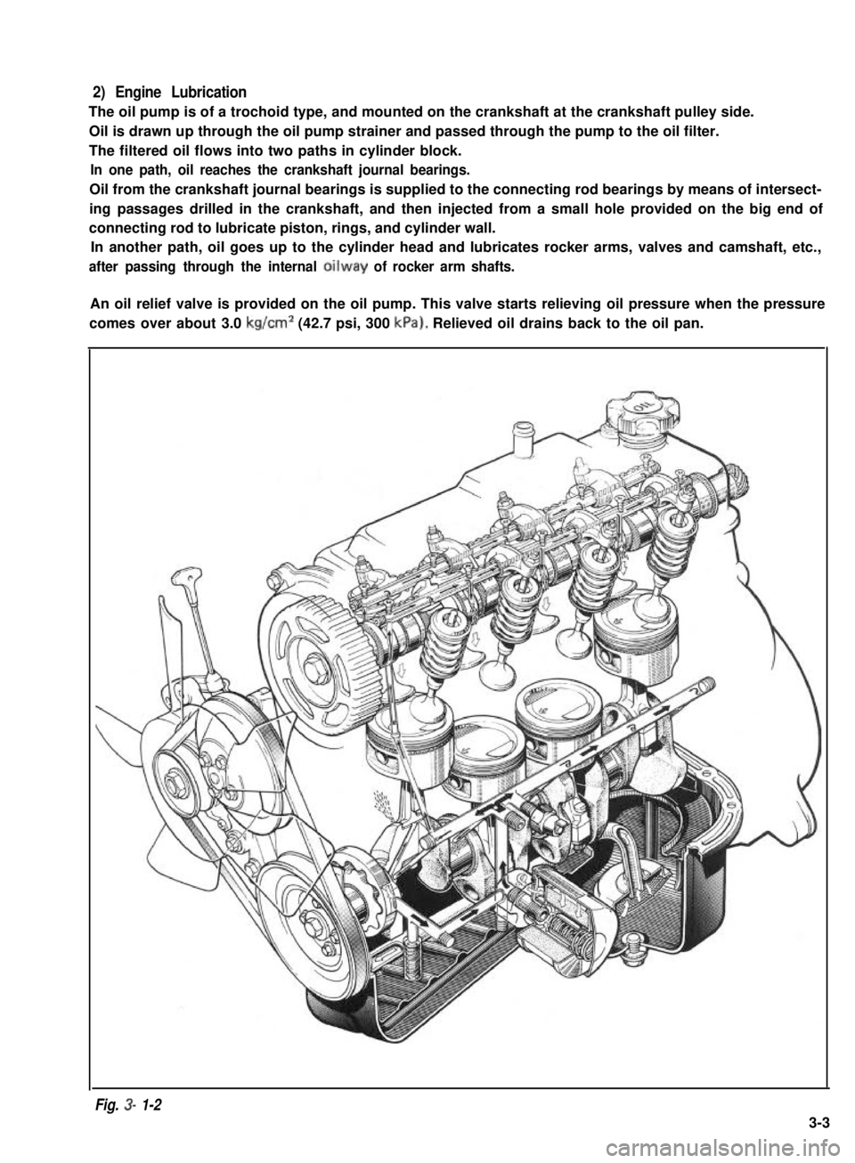
2) Engine Lubrication
The oil pump is of a trochoid type, and mounted on the crankshaft at the crankshaft pulley side.
Oil is drawn up through the oil pump strainer and passed through the pump to the oil filter.
The filtered oil flows into two paths in cylinder block.
In one path, oil reaches the crankshaft journal bearings.
Oil from the crankshaft journal bearings is supplied to the connecting rod bearings by means of intersect-
ing passages drilled in the crankshaft, and then injected from a small hole provided on the big end of
connecting rod to lubricate piston, rings, and cylinder wall.
In another path, oil goes up to the cylinder head and lubricates rocker arms, valves and camshaft, etc.,
after passing through the internal oilway of rocker arm shafts.
An oil relief valve is provided on the oil pump. This valve starts relieving oil pressure when the pressure
comes over about 3.0 kg/cm2 (42.7 psi, 300 kPa). Relieved oil drains back to the oil pan.
Fig. 3- 1-2
3-3