Page 61 of 962
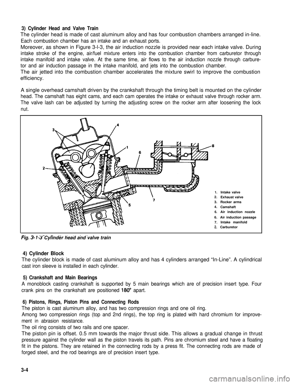
3) Cylinder Head and Valve Train
The cylinder head is made of cast aluminum alloy and has four combustion chambers arranged in-line.
Each combustion chamber has an intake and an exhaust ports.
Moreover, as shown in Figure 3-l-3, the air induction nozzle is provided near each intake valve. During
intake stroke of the engine, air/fuel mixture enters into the combustion chamber from carburetor through
intake manifold and intake valve. At the same time, air flows to the air induction nozzle through carbure-
tor and air induction passage in the intake manifold, and jets into the combustion chamber.
The air jetted into the combustion chamber accelerates the mixture swirl to improve the combustion
efficiency.
A single overhead camshaft driven by the crankshaft through the timing belt is mounted on the cylinder
head. The camshaft has eight cams, and each cam operates the intake or exhaust valve through rocker arm.
The valve lash can be adjusted by turning the adjusting screw on the rocker arm after loosening the lock
nut.
2-
1.Intake valve2.Exhaust valve
3.Rocker arms
4.Camshaft
6.Air induction nozzle
6.Air induction passage
7.Intake manifold
a.Carburetor
-. - _- - ._ . . . . .Fig. 3- 7-3 Cylinder head and valve train
4) Cylinder Block
The cylinder block is made of cast aluminum alloy and has 4 cylinders arranged “In-Line”. A cylindrical
cast iron sleeve is installed in each cylinder.
5) Crankshaft and Main Bearings
A monoblock casting crankshaft is supported by 5 main bearings which are of precision insert type. Four
crank pins on the crankshaft are positioned 180” apart.
6) Pistons, Rings, Piston Pins and Connecting Rods
The piston is cast aluminum alloy, and has two compression rings and one oil ring.
Among two compression rings (top and 2nd rings), the top ring is plated with hard chromium for improve-
ment in abrasion resistance.
The oil ring consists of two rails and one spacer.
The piston pin is offset. 0.5 mm towards the major thrust side. This allows a gradual change in thrust
pressure against the cylinder wall as the piston travels its path. Pins are chromium steel and have a floating
fit in the pistons. They are retained in the connecting rods by a press fit. The connecting rods are made of
forged steel, and the rod bearings are of precision insert type.
3-4
Page 64 of 962
19) Disconnect brake booster vacuum hose from
pipe.
20) Disconnect coupler of lead wire (black) from distributor gear case.
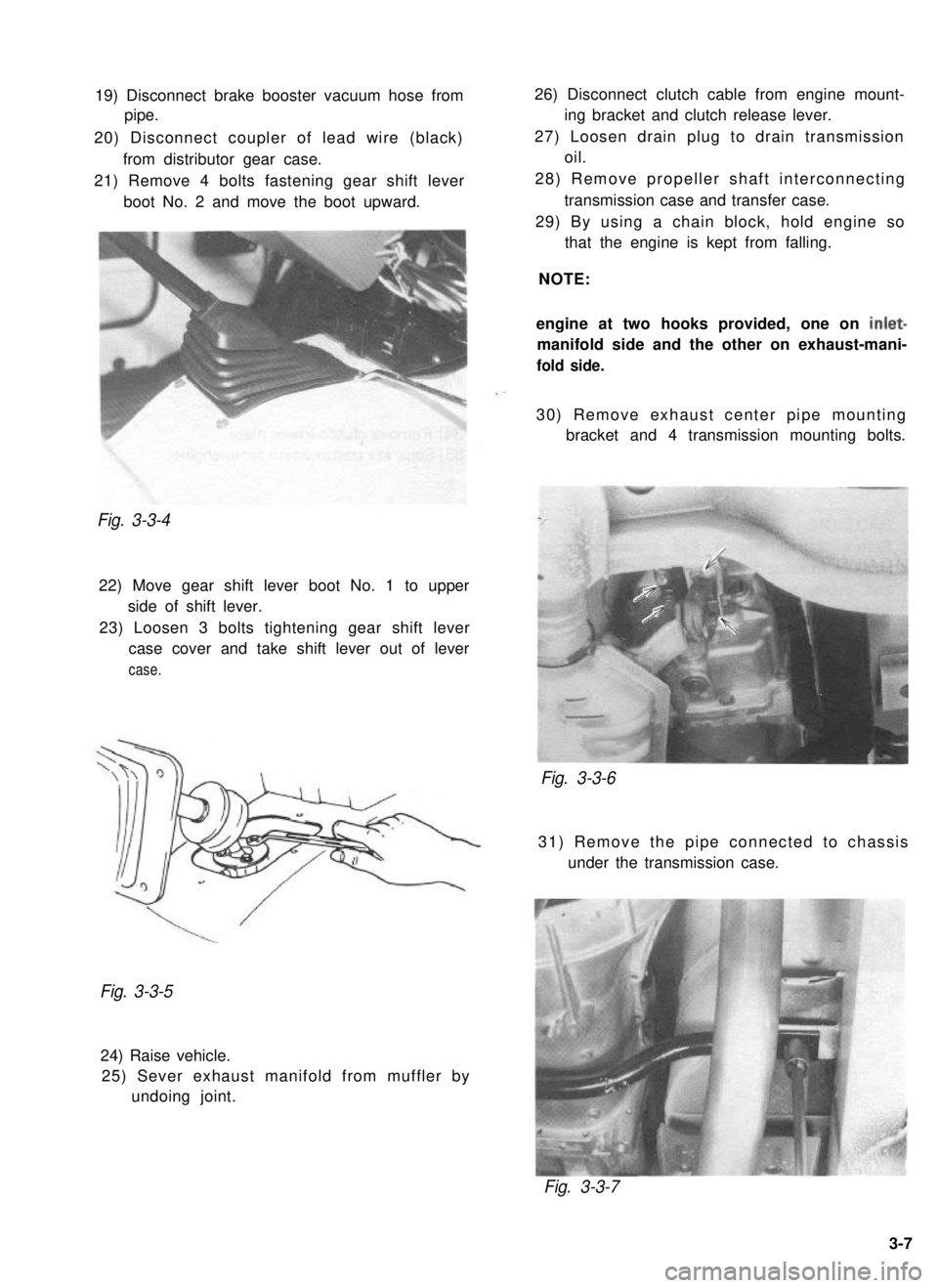
21) Remove 4 bolts fastening gear shift lever boot No. 2 and move the boot upward.Fig. 3-3-4
22) Move gear shift lever boot No. 1 to upperside of shift lever.
23) Loosen 3 bolts tightening gear shift lever case cover and take shift lever out of lever
case.
26) Disconnect clutch cable from engine mount- ing bracket and clutch release lever.
27) Loosen drain plug to drain transmission oil.
28) Remove propeller shaft interconnecting transmission case and transfer case.
29) By using a chain block, hold engine so that the engine is kept from falling.
NOTE:
engine at two hooks provided, one on
inlet-
manifold side and the other on exhaust-mani-
fold side.
30) Remove exhaust center pipe mounting bracket and 4 transmission mounting bolts.
Fig. 3-3-6
31) Remove the pipe connected to chassis
under the transmission case.
Fig. 3-3-5
24) Raise vehicle.25) Sever exhaust manifold from muffler by undoing joint.
Fig. 3-3-7
3-7
Page 68 of 962
10) Remove timing belt tensioner, tensioner
plate, and tensioner spring.
11) Remove camshaft timing belt pulley by lock-
ing camshaft (insert general rod into the cam-
shaft hole) as shown below.
13) Remove crankshaft timing belt pulley key.
14) Remove timing belt inside cover.
Fig. 3-4- 14
15) Remove water pump.
1.Wrench2.Camshaft timing belt pulley
3. Timing belt inside cover4.Generalrod
Fig.3412
12) Using flywheel holder (A) (Special tool),
remove crankshaft timing belt pulley bolt,
pulley and timing belt guide with crank-
shaft locked.
Fig. 3-4- 15
16) Remove exhaust manifold cover.
17) Take off exhaust manifold and its gasket.
Fig. 3-4-13
1.Crankshaft timing belt pulley2. Pulley bolt3. Timing belt guide
Fig. 3-4- 16
3-11
Page 74 of 962
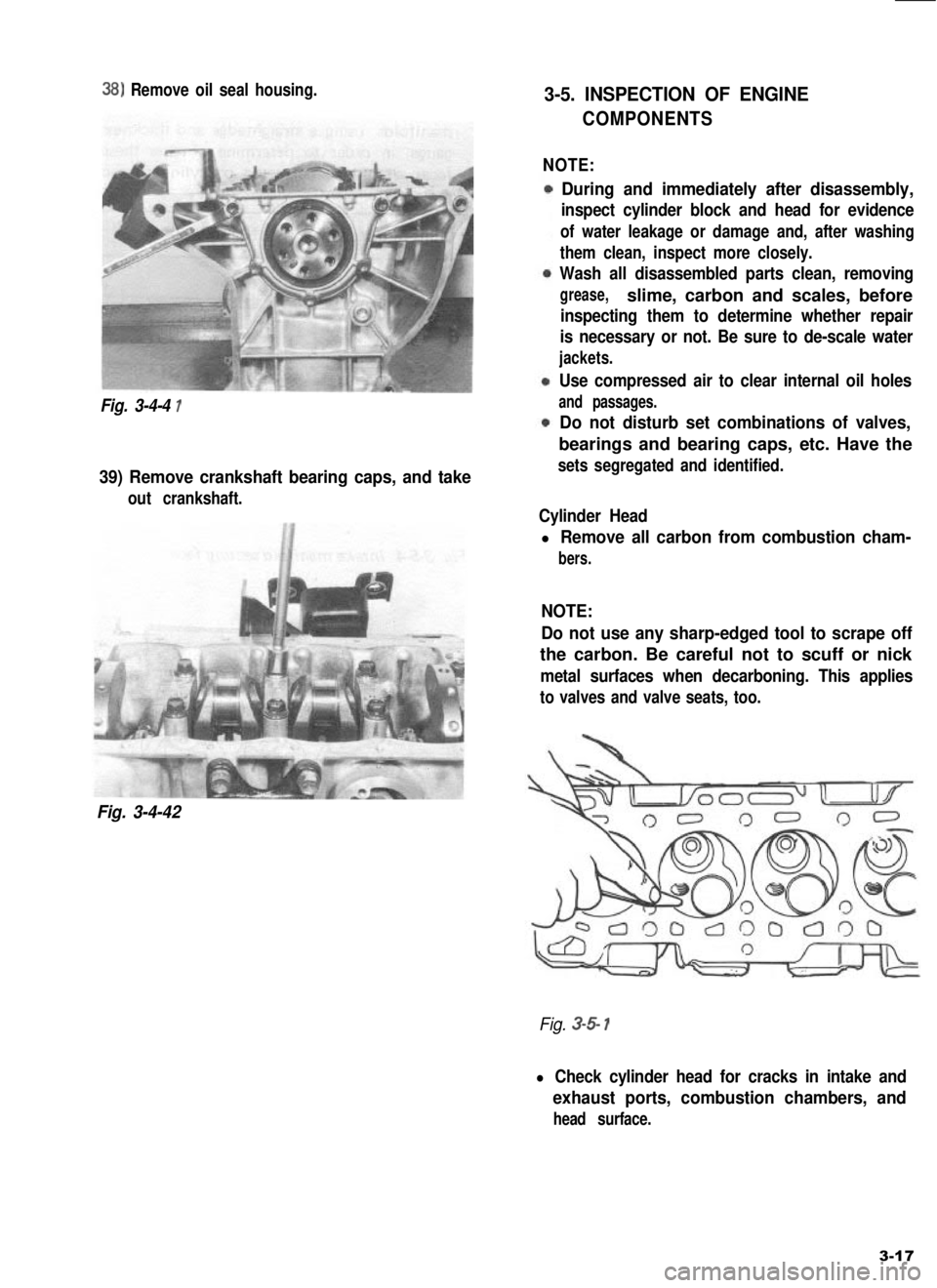
38) Remove oil seal housing.
Fig. 3-4-4 1
39) Remove crankshaft bearing caps, and take
out crankshaft.
Fig. 3-4-42
3-5. INSPECTION OF ENGINE
COMPONENTS
NOTE:
During and immediately after disassembly,
inspect cylinder block and head for evidence
of water leakage or damage and, after washing
them clean, inspect more closely.
Wash all disassembled parts clean, removing
grease,slime, carbon and scales, before
inspecting them to determine whether repair
is necessary or not. Be sure to de-scale water
jackets.
Use compressed air to clear internal oil holes
and passages.
Do not disturb set combinations of valves,
bearings and bearing caps, etc. Have the
sets segregated and identified.
Cylinder Head
l Remove all carbon from combustion cham-
bers.
NOTE:
Do not use any sharp-edged tool to scrape off
the carbon. Be careful not to scuff or nick
metal surfaces when decarboning. This applies
to valves and valve seats, too.
Fig. 3-5 1
l Check cylinder head for cracks in intake and
exhaust ports, combustion chambers, and
head surface.
3-17
Page 76 of 962
Rocker-Arm Shaft and Rocker Arms
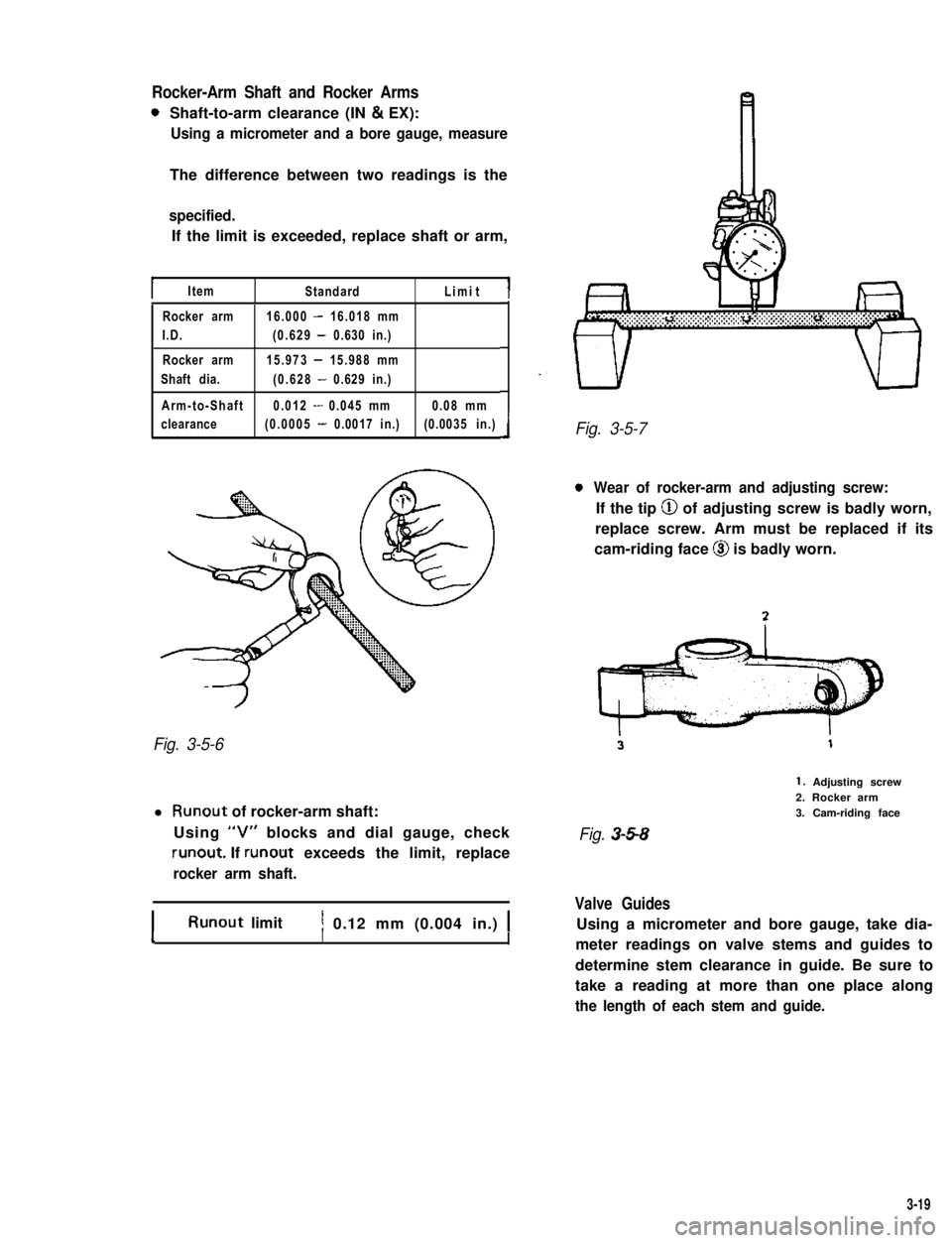
0Shaft-to-arm clearance (IN & EX):
Using a micrometer and a bore gauge, measure
The difference between two readings is the
specified.
If the limit is exceeded, replace shaft or arm,
IItemStandardLimitI
Rocker arm16.000 - 16.018 mm
I.D.(0.629 - 0.630 in.)
Rocker arm15.973 - 15.988 mm
Shaft dia.(0.628 - 0.629 in.)
Arm-to-Shaft0.012 - 0.045 mm0.08 mm
clearance(0.0005 - 0.0017 in.)(0.0035 in.)
Fig. 3-5-6
l Runout of rocker-arm shaft:
Using “V” blocks and dial gauge, check
runout. If runout exceeds the limit, replace
rocker arm shaft.
IRunout limitI1 0.12 mm (0.004 in.) 1II
Fig. 3-5-7
0Wear of rocker-arm and adjusting screw:
If the tip @ of adjusting screw is badly worn,
replace screw. Arm must be replaced if its
cam-riding face @I is badly worn.
1. Adjusting screw2. Rocker arm3. Cam-riding face
Fig. 3-5-8
Valve Guides
Using a micrometer and bore gauge, take dia-
meter readings on valve stems and guides to
determine stem clearance in guide. Be sure to
take a reading at more than one place along
the length of each stem and guide.
3-19
Page 78 of 962
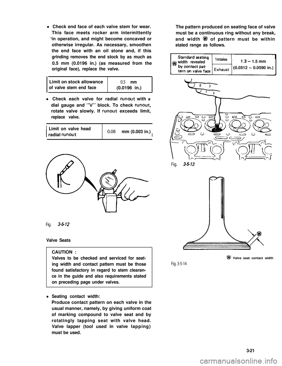
l Check end face of each valve stem for wear.
This face meets rocker arm intermittently
‘in operation, and might become concaved or
otherwise irregular. As necessary, smoothen
the end face with an oil stone and, if this
grinding removes the end stock by as much as
0.5 mm (0.0196 in.) (as measured from the
original face), replace the valve.
Limit on stock allowance0.5 mm
of valve stem end face(0.0196 in.)
l Check each valve for radial runout with a
dial gauge and “V” block. To check runout,
rotate valve slowly. If runout exceeds limit,
replace valve.
I
Limit on valve head
radial runout0.08 mm (0.003 in.)I
Fig. 3-612
Valve Seats
CAUTION :
Valves to be checked and serviced for seat-
ing width and contact pattern must be those
found satisfactory in regard to stem clearan-
ce in the guide and also requirements stated
on preceding page under valves.
l Seating contact width:
Produce contact pattern on each valve in the
usual manner, namely, by giving uniform coat
of marking compound to valve seat and by
rotatingly tapping seat with valve head.
Valve lapper (tool used in valve lapping)
must be used.
The pattern produced on seating face of valve
must be a continuous ring without any break,
and width 6@ of pattern must be within
stated range as follows.
width revealed1.3- 1.5 mm
(0.0512 - 0.0590 in.)
Fig. 3-5-13
Fig. 3-5-14
@ Valve seat contact width
3-21
Page 80 of 962
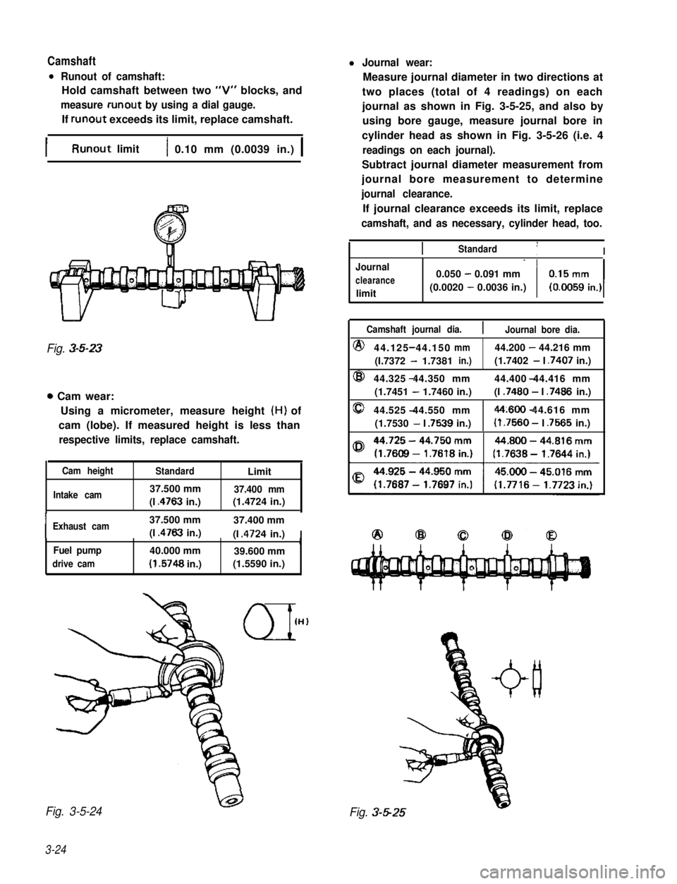
Camshaftl Journal wear:
l Runout of camshaft:
Hold camshaft between two “V” blocks, and
measure runout by using a dial gauge.
If runout exceeds its limit, replace camshaft.
Measure journal diameter in two directions at
two places (total of 4 readings) on each
journal as shown in Fig. 3-5-25, and also by
using bore gauge, measure journal bore in
cylinder head as shown in Fig. 3-5-26 (i.e. 4
readings on each journal).
Subtract journal diameter measurement from
journal bore measurement to determine
journal clearance.
If journal clearance exceeds its limit, replace
camshaft, and as necessary, cylinder head, too.
IRunout limit1 0.10 mm (0.0039 in.) 1
Fig. 3-5-23
0 Cam wear:
Using a micrometer, measure height (H) of
cam (lobe). If measured height is less than
respective limits, replace camshaft.
Cam heightStandardLimit
Intake cam37.500 mm37.400 mm
(I .4763 in.)(1.4724 in.),
IExhaust cam37.500 mm37.400 mm
(I .4763 in.)(I .4724 in.)IrFuel pump40.000 mm39.600 mm
drive cam(I .5748 in.)(1.5590 in.)
Fig. 3-5-24
3-24
IIStandard1I
Journal
clearance
limit
0.050 - 0.091 mm
(0.0020 - 0.0036 in.)
Camshaft journal dia.Journal bore dia.
@44.125 44.150-mm44.200 - 44.216 mm
(I.7372 - 1.7381in.)(1.7402 - I .7407 in.)
@44.325 44.350 mm- 44.400 44.416 mm
(1.7451 - 1.7460 in.)(I .7480 - I .7486 in.)
044.525 44.550 mm-44~600 44.616 mm-
(1.7530 - I .7539 in.)(I .7560 - I .7565 in.)
Fig. 3-5-25
Page 81 of 962
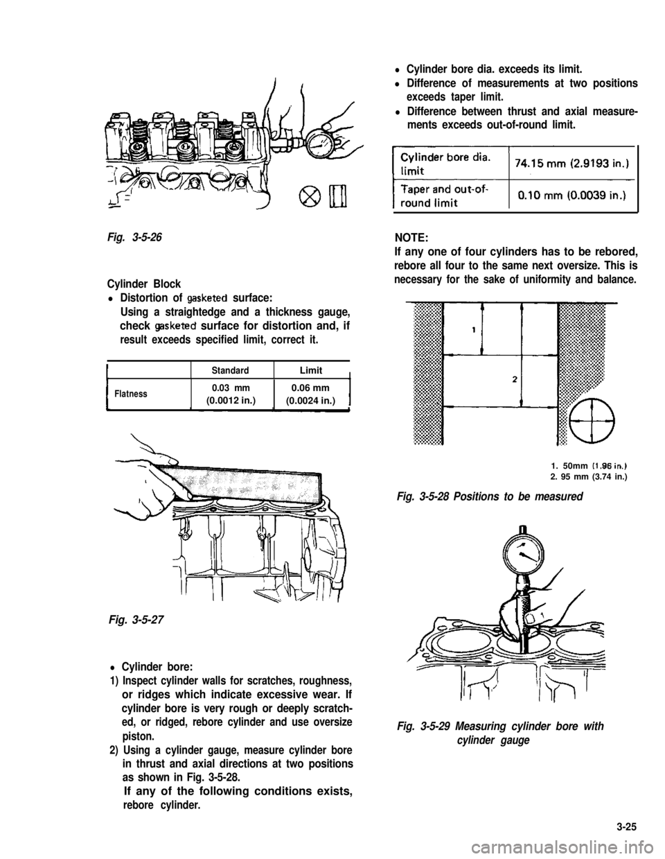
Fig. 3-5-26
Cylinder Block
l Distortion of gasketed surface:
Using a straightedge and a thickness gauge,
check gasketed surface for distortion and, if
result exceeds specified limit, correct it.
StandardLimitI
IFlatness0.03 mm0.06 mm
(0.0012 in.)(0.0024 in.)I
Fig. 3-5-27
l Cylinder bore:
1) Inspect cylinder walls for scratches, roughness,
or ridges which indicate excessive wear. If
cylinder bore is very rough or deeply scratch-
ed, or ridged, rebore cylinder and use oversize
piston.
2) Using a cylinder gauge, measure cylinder bore
in thrust and axial directions at two positions
as shown in Fig. 3-5-28.
If any of the following conditions exists,
rebore cylinder.
l Cylinder bore dia. exceeds its limit.
l Difference of measurements at two positions
exceeds taper limit.
l Difference between thrust and axial measure-
ments exceeds out-of-round limit.
NOTE:
If any one of four cylinders has to be rebored,
rebore all four to the same next oversize. This is
necessary for the sake of uniformity and balance.
1. 50mm (1.96in.j
2. 95 mm (3.74 in.)
Fig. 3-5-28 Positions to be measured
Fig. 3-5-29 Measuring cylinder bore with
cylinder gauge
3-25