Page 292 of 962
14-4. TRANSFER SERVICES NOT REQUIRING TRANSFER REMOVAL
Following parts or components do not require transfer removal to receive services (replacement, inspec-
tion) :
Part or ComponentNature of Service
1. Universal-joint yoke flangesReplacement or inspection
2. Front drive shift shaft forkReplacement or inspectionI
3. Transfer output front shaft oil seal
4. Transfer output front shaft bearing
5. Transfer output front shaft
Replacement or inspection
Replacement
Replacement
6. Transfer front caseReplacement
7. Front drive clutch hubReplacement or inspection
8. Front drive clutch sleeveReplacement or inspection
9. Transfer input shaft oil sealReplacement
10. 4WD indicator light switchReplacement or inspection
11. Speedometer driven gearReplacement or inspection
12. Gear shift control leverReplacement or inspection
13. Gear shift control boot No. 1, No. 2Replacement
14. Gear shift control lever spring seatReplacement or inspection.
14-5
Page 294 of 962
6) Disconnect 4WD switch lead wire at coupler.
7) Remove 3 mounting nuts securing gear box
to chassis, and take down gear box.
14-7
Fig. 14-11
Page 301 of 962
4WD Gear Shift Lever
Check lower end of gear shift lever where gear
shift fork shaft contacts @ for wear and any
kind of damage. Worn or damaged shift lever
must be replaced with new one.
14-8. REASSEMBLY
NOTE:
l All parts to be used in reassembly must be
perfectly clean.
l Oil or grease sliding and rubbing surfaces of
transfer components just before using them
in reassembly with gear oil and SUZUKI
SUPER GREASE A (99000-25010).
l Oil seals, “0” rings, gaskets and similar sealing
members must be in perfect condition. For
these members, use replacement parts in
stock.
l Tightening torque is specified for important
fasteners- mainly bolts - of transfer and
other components. Use torque wrenches and
constantly refer to specified data given in
P. 14-23.
Fig. 14-42
Input Shaft
Press-fit bearings onto both sides of input shaft
by using bearing installer (special tool).
Bearing installer (A) : (09913-84510)
(A)
Fig. 14-43
14-14
Page 308 of 962
Front Case
1) Install bearing, circlip and oil seal to front
case. Apply grease to oil seal lip and install
output front shaft using bearing installer
(special tool).
Bearing installer (A) : (09913-76010)
Fig. 14-64
2) Put gasket on center case.
3) Check front case to ensure that it is provided
with 2 dowel pins.
Fig. 14-65
4) Install front case to center case.
Fig. 14-66
5) When installing speedometer driven gear
and its gear case in rear case, apply grease to
0 ring and oil seal lip, and align bolt holes
in rear case and driven gear case.
Fig. 14-67
6) Install 4WD ball and switch. Then clamp
switch lead wire properly.
/1.6 - 2.3 kgm
Fig. 14-68 (12.0 - 16.5 lb-h)
14-21
Page 450 of 962

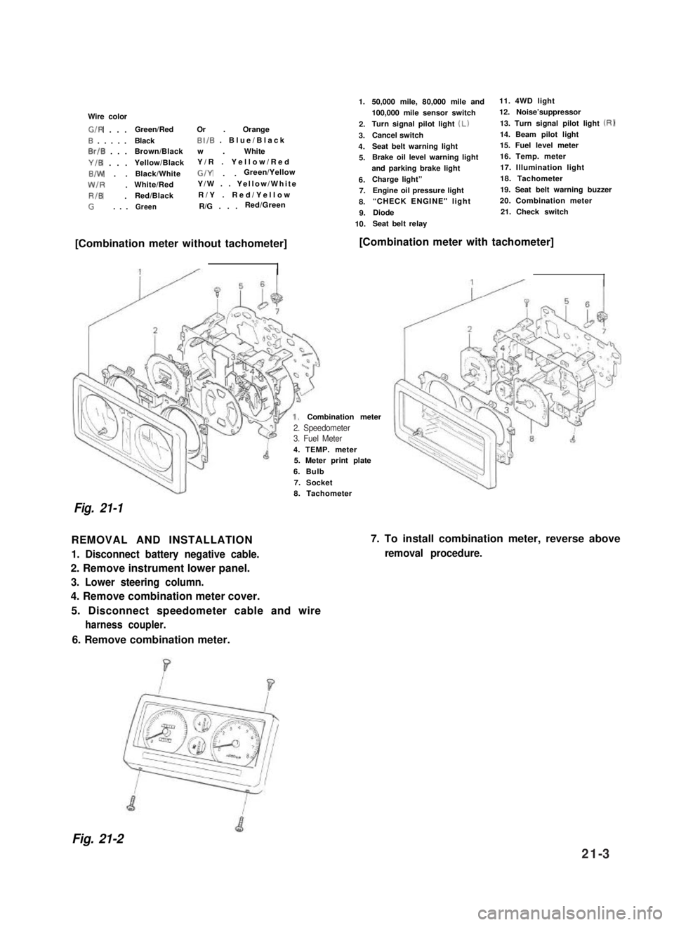
Wire color
G/R . . .Green/RedOr . Orange
0 . . . . .BlackBI/B . Blue/Black
0rlB . . .Brown/Blackw . White
Y/B . . .Yellow/BlackY/R . Yellow/Red
B/W . .Black/WhiteG/Y . .Green/Yellow
W/R .White/RedY/W . . Yellow/White
RIB .Red/BlackR/Y . Red/Yellow
G. . .GreenR/G . . .Red/Green
1.
2.
3.
4.
5.
6.7.
8.
9.
10.
50,000 mile, 80,000 mile and11. 4WD light
100,000 mile sensor switch12. Noise’suppressor
Turn signal pilot light (Lb13. Turn signal pilot light (RI
Cancel switch14. Beam pilot light
Seat belt warning light15. Fuel level meter
Brake oil level warning light16. Temp. meter
and parking brake light17. Illumination light
Charge light”18. Tachometer
Engine oil pressure light19. Seat belt warning buzzer
“CHECK ENGINE" light 20. Combination meter
Diode21. Check switch
Seat belt relay
[Combination meter without tachometer][Combination meter with tachometer]
4. TEMP. meter5. Meter print plate
6. Bulb
7. Socket
Combination meter
Fig. 21-1
8. Tachometer
REMOVAL AND INSTALLATION
1. Disconnect battery negative cable.
2. Remove instrument lower panel.
3. Lower steering column.
4. Remove combination meter cover.
5. Disconnect speedometer cable and wire
harness coupler.
7. To install combination meter, reverse above
removal procedure.
6. Remove combination meter.
Fig. 21-2
2. Speedometer3. Fuel Meter
21-3
Page 462 of 962

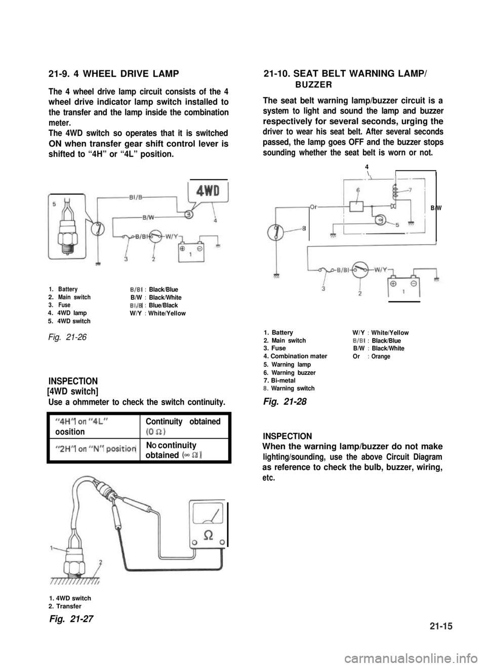
21-9. 4 WHEEL DRIVE LAMP21-10. SEAT BELT WARNING LAMP/
BUZZERThe 4 wheel drive lamp circuit consists of the 4
wheel drive indicator lamp switch installed to
the transfer and the lamp inside the combination
meter.
The 4WD switch so operates that it is switched
ON when transfer gear shift control lever is
shifted to “4H” or “4L” position.
The seat belt warning lamp/buzzer circuit is a
system to light and sound the lamp and buzzer
respectively for several seconds, urging the
driver to wear his seat belt. After several seconds
passed, the lamp goes OFF and the buzzer stops
sounding whether the seat belt is worn or not.
1.BatteryB/B1:Black/Blue2.Main switchB/W:Black/White3.FuseBI/B:Blue/Black4.4WD lampW/Y:White/Yellow5.4WD switch
Fig. 21-26
INSPECTION
[4WD switch]
Use a ohmmeter to check the switch continuity.
I
“4H” or “4L”Continuity obtained
oosition(052)I
I
#,2HM or ##N## positionNO continuity
obtained (- 52 1I
CL-
01
8
4\II
B/W
1. Battery
2. Main switch3. Fuse
4. Combination mater
5. Warning lamp
6. Warning buzzer7. Bi-metal8. Warning switch
W/Y:White/Yellow
BIBI:Black/BlueB/W:Black/White
Or:Orange
Fig. 21-28
INSPECTION
When the warning lamp/buzzer do not make
lighting/sounding, use the above Circuit Diagram
as reference to check the bulb, buzzer, wiring,
etc.
1. 4WD switch
2. Transfer
Fig. 21-2721-15
Page 466 of 962
21-15. WIRING HARNESS ROUTING
When reinstalling wire harness, be careful for the following.
l When doing wiring harness related work, make always sure to disconnect battery negative cable from
battery.
l Clamp wire harness securely at prescribed positions.
l Try to route wire harness so as to avoid contact with other parts as much as possible. Use special care
not to let it contact sharp edges of body or other parts.
0 Connect connectors securely.
Engine Room Wiring
1.Wire harness No. 2
2.Battery3. To starter, alternator, head light, small light, horn and etc.
4. To license light, stop/tail light, 4WD switch
5.Earth
6.To wiring harness No.17. To head light, small light, etc.
8.To distributor
9. To ignition coil
10. To back up light switch
11. To fifth switch
12.To TWSV
13.Duty check coupler
14. Thermal engine room switch
15. HAC
16.Ignition coil
17.Brake fluidreservoir
Fig. 27-37
21-19
Page 467 of 962
1.Battery2.Fusible link
3.To starter
4. To starter, alternator, etc
5.Earth6. Earth (To starter mounting bolt)7.Wiring harnessNo.2
64
1
I
1.From wire harnessNo.22. TWSV (Three way solenoid valve)
3. Water temperautre gauge4.Alternator5.Intake manifold
6.Clamp
7.ToVSV6.Thermal switch
9. Mount this terminal horizontal-ly as shown
10.Thermostat cap
1. Wire harness No. 2
2. To distributor
3. To fifth switch4. To back up light switch5. To ignition coil6. Condensor
7. Noise suppressor filter(Clamp it toward engineroom so as to prevent itfrom contacting dashpanel edge.)6. Earth9. To license light, stop/taillight, 4WD switch
10. Ignition coil
11. Distributor12. To wire harness No. 2
13. Ignition coil cap
Fig. 21-38
21-20