1987 SUZUKI GRAND VITARA service indicator
[x] Cancel search: service indicatorPage 32 of 962

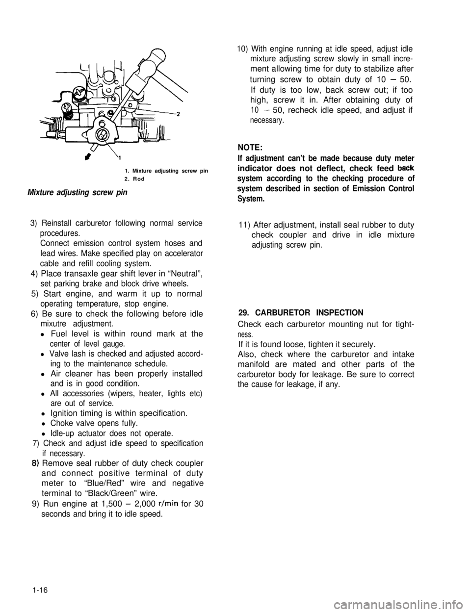
1. Mixture adjusting screw pin
2. Rod
Mixture adjusting screw pin
10) With engine running at idle speed, adjust idle
mixture adjusting screw slowly in small incre-
ment allowing time for duty to stabilize after
turning screw to obtain duty of 10 - 50.
If duty is too low, back screw out; if too
high, screw it in. After obtaining duty of
10- 50, recheck idle speed, and adjust if
necessary.
NOTE:
If adjustment can’t be made because duty meter
indicator does not deflect, check feed baCk
system according to the checking procedure of
system described in section of Emission Control
System.
3) Reinstall carburetor following normal service
procedures.
Connect emission control system hoses and
lead wires. Make specified play on accelerator
cable and refill cooling system.
11) After adjustment, install seal rubber to duty
check coupler and drive in idle mixture
adjusting screw pin.
4) Place transaxle gear shift lever in “Neutral”,
set parking brake and block drive wheels.
5) Start engine, and warm it up to normal
operating temperature, stop engine.
6) Be sure to check the following before idle
mixutre adjustment.
l Fuel level is within round mark at the
center of level gauge.
l Valve lash is checked and adjusted accord-
ing to the maintenance schedule.
l Air cleaner has been properly installed
and is in good condition.
l All accessories (wipers, heater, lights etc)
are out of service.
29. CARBURETOR INSPECTION
Check each carburetor mounting nut for tight-
ness.
If it is found loose, tighten it securely.
Also, check where the carburetor and intake
manifold are mated and other parts of the
carburetor body for leakage. Be sure to correct
the cause for leakage, if any.
l Ignition timing is within specification.
l Choke valve opens fully.
l Idle-up actuator does not operate.
7) Check and adjust idle speed to specification
if necessary.
8) Remove seal rubber of duty check coupler
and connect positive terminal of duty
meter to“Blue/Red” wire and negative
terminal to “Black/Green” wire.
9) Run engine at 1,500 - 2,000 r/min for 30
seconds and bring it to idle speed.
1-16
Page 143 of 962

3) Reinstall carburetor following normal service
procedures.
Connect emission control system hoses and
lead wires. Make specified play on accelerator
cable and refill cooling system.
4) Place transaxle gear shift lever in “Neutral”,
set parking brake and block drive wheels.
5) Start engine, and warm it up to normal
operating temperature, stop engine.
6) Be sure to check the following before idle
mixture adjustment.
l Fuel level is within round mark at the
center of level gauge.
l Valve lash is checked and adjusted accord-
ing to the maintenance schedule.
l Air cleaner has been properly installed
and is in good condition.
l All accessories (wipers, heater, lights etc)
are out of service.
l Ignition timing is within specification.
l Choke valve opens fully.
l Idle-up actuator does not operate.
7) Check and adjust idle speed to specification
if necessary.
8) Remove seal rubber of duty check coupler
and connect positive terminal of duty
meter to“Blue/Red” wire and negative
terminal to “Black/Green” wire.
9) Run engine at 1,500 - 2,000 r/min for 30
seconds and bring it to idle speed.
10) With engine running at idle speed, adjust idle
mixture adjusting screw slowly in small incre-
ment allowing time for duty to stabilize after
turning screw to obtain duty of 10 - 50.
If duty is too low, back screw out; if too
high, screw it in. After obtaining duty of
10 - 50, recheck idle speed, and adjust if
necessary.
NOTE:
If adjustment can’t be made because duty meter
indicator does not deflect, check feed back
system according to the checking procedure of
system described in section of Emission Control
System.
11) After adjustment, install seal rubber to duty
check coupler and drive in idle mixture
adjusting screw pin.
4-28
Page 175 of 962

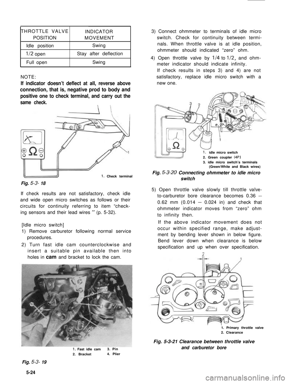
THROTTLE VALVEINDICATOR
POSITIONMOVEMENT
Idle positionSwing
l/2 openStay after deflection
Full openSwing
NOTE:
If indicator doesn’t deflect at all, reverse above
connection, that is, negative prod to body and
positive one to check terminal, and carry out the
same check.
Fig. 53- 18
1. Check terminal
If check results are not satisfactory, check idle
and wide open micro switches as follows or their
circuits for continuity referring to item “check-
ing sensors and their lead wires ” (p. 5-32).
[Idle micro switch]
1) Remove carburetor following normal service
procedures.
2) Turn fast idle cam counterclockwise and
insert a suitable pin available then into
holes in cam and bracket to lock the cam.
1, Fast idle cam3. Pin
2. Bracket4. Plier
3) Connect ohmmeter to terminals of idle micro
switch. Check for continuity between termi-
nals. When throttle valve is at idle position,
ohmmeter should indicated “zero” ohm.
4) Open throttle valve by l/4 to l/2, and ohm-
meter indicator should indicate infinity.
If check results in steps 3) and 4) are not
satisfactory, replace idle micro switch with a
new one.
1.idle micro switch
2. Green coupler (4P)
3. idle micro switch’s terminals(Green/White and Black wires)
Fig. 5-3-20 Connecting ohmmeter to idle micro
switch
5) Open throttle valve slowly till throttle valve-
to-carburetor bore clearance becomes 0.36 -
0.62 mm (0.014 - 0.024 in) and check that
ohmmeter indicator moves from “zero” ohm
to infinity then.
If the above indicator movement does not
occur within specified range, make adjust-
ment by bending lever shown in below figure.
Bend lever down when clearance is below
specification and up when over specification.
n
1. Primary throttle valve2. Clearance
Fig. 5-3-21 Clearance between throttle valve
and carburetor bore
Fig. 5-3- 19
5-24 4
Page 176 of 962
![SUZUKI GRAND VITARA 1987 Service Repair Manual Fig. 5-3-22 Lever
1. Lever
.
[Wide open micro switch]
1) Connect ohmmeter to wide open micro
switch as indicated in below figure.
At this time, ohmmeter indicator should
indicate “zero” ohm.
2) Wh SUZUKI GRAND VITARA 1987 Service Repair Manual Fig. 5-3-22 Lever
1. Lever
.
[Wide open micro switch]
1) Connect ohmmeter to wide open micro
switch as indicated in below figure.
At this time, ohmmeter indicator should
indicate “zero” ohm.
2) Wh](/manual-img/20/57437/w960_57437-175.png)
Fig. 5-3-22 Lever
1. Lever
.
[Wide open micro switch]
1) Connect ohmmeter to wide open micro
switch as indicated in below figure.
At this time, ohmmeter indicator should
indicate “zero” ohm.
2) When throttle valve is fully opened, ohmmeter
should indicate infinity.
If any defect, replace.
1. Wide open micro switch
2. Yellow coupler
3. Green coupler (4P)4. Wide open micro switch’sterminals(Green and Black/Yellow wires)
Fig. 5-3-23 Checking wide open micro switch
3) Open throttle valve gradually until the ohm-
meter indicates infinity. Then, using a vernier,
measure the clearance between throttle valve
and carburetor bore as shown in below figure.
The clearance should be within 6.0 - 7.2 mm
(0.24- 0.28 in). If the clearance is out of
specified range, make adjustment by bending
the lever in below figure.
1. Primary throttle valve2. Clearance
Fig. 5-3-24 Clearance between throttle valve
and carburetor bore
1. Wide open micro switch lever
Fig. 5-3-25 Wide open micro switch lever
Upon completion of checks, install carburetor
following normal service procedures.
Checking mixture control solenoid valve
1) Check to make sure that ignition switch is at
“OFF” position.
2) Disconnect couplers from ECM, TWSVs and
vsv.
3) Disconnect mixture control solenoid valve
lead wires at the coupler (5P).
Fig. 5-3-26
1. Green coupler (BP)
5-25
Page 236 of 962

The alternator features a solid state regulator
that is mounted inside the alternator. All regula-
tor components are enclosed into a solid mold,
and this unit along with the brush holder assemb-
ly is attached to the slip ring end frame. The
regulator voltage setting cannot be adjusted.
The alternator rotor bearings contain enough
grease to eliminate the need for periodic lubri-
cation. Two brushes carry current through the
two slip rings to the field coil mounted on the
rotor, and under normal conditions will provide
long period of attention-free service.
The stator windings are assembled on the inside
of a laminated core that forms part of the
alternator frame. A rectifier bridge connected
to the stator windings contains six diodes,
and electrically changes the stator A.C. voltages
to a D.C. voltage which appears at the generator
output terminal.
The neutral diodes serve to convert the voltage
fluctuation at the neutral point to direct current
for increasing the alternator output.
A condenser mounted in the end frame protects
the diodes from high voltages and suppresses
radio noise.
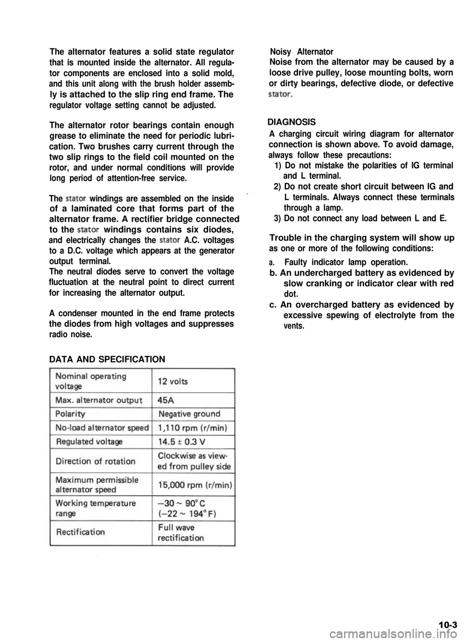
DATA AND SPECIFICATION
Nominal operating
voltaga
Max. alternator output
12 volts
45A
No-load alternator speed
IDirection of rotationClockwise as view-
ed from oullev side
Maximum permissible
alternator speed
Working temperature
range
Rectification
15,000 rpm (r/min)
-3o- 90°C
(-22 - 194” F)
Full wave
rectification
Noisy Alternator
Noise from the alternator may be caused by a
loose drive pulley, loose mounting bolts, worn
or dirty bearings, defective diode, or defective
stator.
DIAGNOSIS
A charging circuit wiring diagram for alternator
connection is shown above. To avoid damage,
always follow these precautions:
1) Do not mistake the polarities of IG terminal
and L terminal.
2) Do not create short circuit between IG and
L terminals. Always connect these terminals
through a lamp.
3) Do not connect any load between L and E.
Trouble in the charging system will show up
as one or more of the following conditions:
a.Faulty indicator lamp operation.
b. An undercharged battery as evidenced by
slow cranking or indicator clear with red
dot.
c. An overcharged battery as evidenced by
excessive spewing of electrolyte from the
vents.
10-3
Page 250 of 962

Clutch Disc Facing Surface Condition
A burnt or glazed (glass-like surface) facing can
be reconditioned by grinding it with No. 120 -
200 sandpaper. If surface is in bad condition
beyond repair, replace whole clutch disc assemb-
ly.
11-3. INSPECTION OF COMPONENTSBacklash in Disc Setration Fit
Check backlash by turning disc back and forth
as mounted on transmission input shaft. Replace
disc assembly if backlash is noted to exceed
service limit. Backlash here is a circular displace-
ment as measured with a dial indicator.
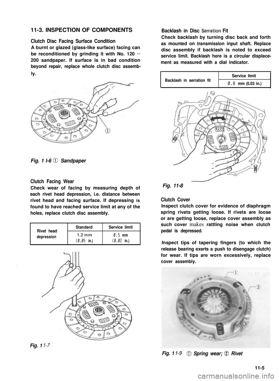
Fig. 1 l-6 @ Sandpaper
Clutch Facing Wear
Check wear of facing by measuring depth of
each rivet head depression, i.e. distance between
rivet head and facing surface. If depressing is
found to have reached service limit at any of the
holes, replace clutch disc assembly.
Rivet head
depression
Standard
1.2mm
(0.05 in.)
Service limit
0.5 mm
(0.02 in.)
Backlash in serration fitService limit
0.8 mm (0.03 in.)
Fig. 11-8
Clutch Cover
Inspect clutch cover for evidence of diaphragm
spring rivets getting loose. If rivets are loose
or are getting loose, replace cover assembly as
such cover makes rattling noise when clutch
pedal is depressed.
Inspect tips of tapering fingers (to which the
release bearing exerts a push to disengage clutch)
for wear. If tips are worn excessively, replace
cover assembly.
Fig. 1 l-7
Fig. 1 l-9@ Spring wear; @ Rivet
11-5
Page 292 of 962

14-4. TRANSFER SERVICES NOT REQUIRING TRANSFER REMOVAL
Following parts or components do not require transfer removal to receive services (replacement, inspec-
tion) :
Part or ComponentNature of Service
1. Universal-joint yoke flangesReplacement or inspection
2. Front drive shift shaft forkReplacement or inspectionI
3. Transfer output front shaft oil seal
4. Transfer output front shaft bearing
5. Transfer output front shaft
Replacement or inspection
Replacement
Replacement
6. Transfer front caseReplacement
7. Front drive clutch hubReplacement or inspection
8. Front drive clutch sleeveReplacement or inspection
9. Transfer input shaft oil sealReplacement
10. 4WD indicator light switchReplacement or inspection
11. Speedometer driven gearReplacement or inspection
12. Gear shift control leverReplacement or inspection
13. Gear shift control boot No. 1, No. 2Replacement
14. Gear shift control lever spring seatReplacement or inspection.
14-5