1987 SUZUKI GRAND VITARA low oil pressure
[x] Cancel search: low oil pressurePage 23 of 962

NOTE:
Steps 1) - 6) outlined above must be performed
with ENGINE NOT RUNNING. For step 7),
be sure to have adequate ventilation while
engine is running
It is recommended to use engine oil of SE or
SF class.
NOTE:For temperatures below
32”F(O”C), it is highly
recommended to use SAE 5W-30 oil.
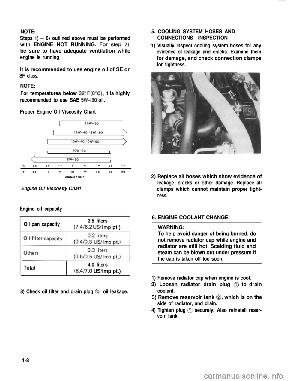
Proper Engine Oil Viscosity Chart
12OW-50
lSW-40.15w-501
Ilow-4O.lOW-50
Ilow-30I
5w-30I“C-3 0 -2
0 -1
0 0 102
0
30 4
0
OF-2 2 -
4 14
32506886104
Temperatur e
Engine Oil Viscosity Chart
Engine oil capacity
Oil pan capacity 3.5 liters (7.4/6.2
US/Imp pt.)I
Total 4.0 liters(8.4/7.0 US/Imp pt.)I
8) Check oil filter and drain plug for oil leakage.
5. COOLING SYSTEM HOSES AND
CONNECTIONS INSPECTION
1) Visually inspect cooling system hoses for any
evidence of leakage and cracks. Examine them
for damage, and check connection clamps
for tightness.
2) Replace all hoses which show evidence of
leakage, cracks or other damage. Replace all
clamps which cannot maintain proper tight-
ness.
6. ENGINE COOLANT CHANGE
WARNING:
To help avoid danger of being burned, do
not remove radiator cap while engine and
radiator are still hot. Scalding fluid and
steam can be blown out under pressure if
the cap is taken off too soon.
1) Remove radiator cap when engine is cool.
2) Loosen radiator drain plug @
to drain
coolant.
3) Remove reservoir tank 0, which is on the
side of radiator, and drain.
4) Tighten plug
@ securely. Also reinstall reser-
voir tank.
1-8
Page 35 of 962

3) Install spindle, bearings, wheel hub, bearing
nut and brake disc referring to INSTALLA-
TION (p. 17-12) of SECTION 17.
4) Adjust bearing preload and then tighten
bearing lock nut to specification. Refer to
MAINTENANCE (p. 17-21) of SECTION 17.
5) Install drive flange or free wheeling hub (if
equipped), brake caliper with mounting and
wheel referring to INSTALLATION (p. 17-
12) of SECTION 17.
For tightening torque of each bolt and nut,
refer to torque table (p. 17-26) of SECTION
17.
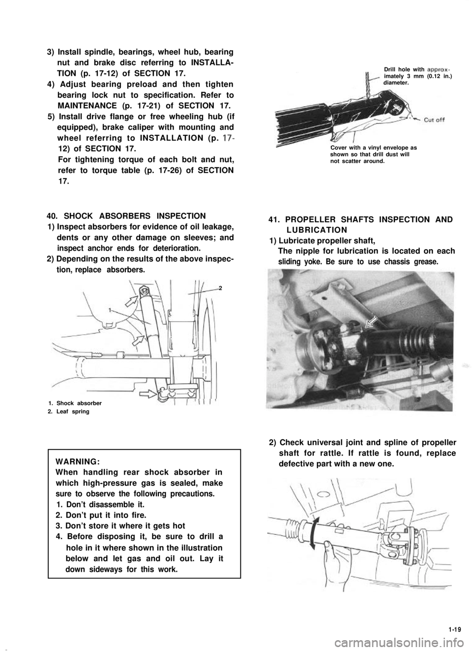
40. SHOCK ABSORBERS INSPECTION
1) Inspect absorbers for evidence of oil leakage,
dents or any other damage on sleeves; and
inspect anchor ends for deterioration.
2) Depending on the results of the above inspec-
tion, replace absorbers.
2
1. Shock absorber
2. Leaf spring
WARNING:
When handling rear shock absorber in
which high-pressure gas is sealed, make
sure to observe the following precautions.
1. Don’t disassemble it.
2. Don’t put it into fire.
3. Don’t store it where it gets hot
4. Before disposing it, be sure to drill a
hole in it where shown in the illustration
below and let gas and oil out. Lay it
down sideways for this work.
Drill hole with approx-imately 3 mm (0.12 in.)diameter.
Cover with a vinyl envelope asshown so that drill dust willnot scatter around.
41. PROPELLER SHAFTS INSPECTION AND
LUBRICATION
1) Lubricate propeller shaft,
The nipple for lubrication is located on each
sliding yoke. Be sure to use chassis grease.
2) Check universal joint and spline of propeller
shaft for rattle. If rattle is found, replace
defective part with a new one.
1-19
Page 42 of 962

ConditionPossible causeCorrection
Not enough powerEmission control
1. Malfunctioning EGR valve
Check and replace as
necessary.
Check and replace as
2. Malfunctioning bowl vent solenoid valve.necessary.
Check and replace as
3. Malfunctioning high altitude switch.necessary
Check nad replace as
4. Malfunctioning throttle position switch
(wide open switch)
necessary
Others
1. Dragging brakes
2. Slipping clutch
.Repair or replace
Adjust or replace
Engine hesitatesAbnormal condition in electrical systems
(Momentary lack of1. Defective spark plug or plug gap out ofReplace or adjust gap
response as the acceler-
ator
adjustment
is depressed. Can2. Cracked rotor or cap in distributor,Replace
occur at all car speeds.resulting in leakage
Usually most severe3. Deteriorated ignition coil, or crackReplace
when first trying toresulting in leakage
make the car move, as4. Leaky high-tension cordsReplace
from a stop sign.)5. Ignition timing out of adjustmentAdjust as prescribed
Abnormal condition in fuel system
1. Improper adjustment of float level
2. Clogged carburetor jets
3. Malfunctioning accelerator pump
Adjust
Clean
Check and replace as
necessary
4. Inadequately discharging fuel pumpReplace
Abnormal condition in engine
1. Loss of compression pressure due to leaky
cylinder head gasket
Replace
2. Compression pressure too low because ofReplace and rebore as
worn pistons, rings, cylinders or burnt valvesnecessary
Emission control
1. Malfunctioning bowl vent solenoid valveCheck and replace as
necessary
2. Malfunctioning throttle position switch
(wide open switch)
3. Malfunctionnig high altitude switch
4. Malfunctioning EGR valve
Check and replace as
necessary
Check and replace as
necessary
Check and replace as
necessary
5. Malfunctioning thermostatically controlled
air cleaner
Check and replace as
necessary
2-4
Page 46 of 962

ConditionPossible causeCorrection
High fuel consumptionAbnormal condition ignition system
1. Improper ignition timingAdjust
2. Leak or loose connection of high tension cordRepair or replace
3. Defective spark plug (improper gap, heavyClean, adjust or replace
deposits, and burned electrodes, etc..)
4. Cracked distributor cap or rotorReplace
5. Malfunctioning mechanical and vacuumCheck and repair or
advancers in distributorreplace
Abnormal condition in fuel system
1. Improper float levelAdjust
2. Fuel leakage from tank, pipe or carburetorRepair or replace
3. Malfunctioning carburetor choke systemRepair or replace
4. Dirty or clogged carburetor jetsClean
5. Clogged air cleaner elementClean or replace
6. Malfunctioning thermostatically controlledCheck and repair or
air cleanerreplace
Abnormal condition in engine
1. Low compressionPreviously outlined
2. Poor valve seatingRepair or replace
3. Improper valve clearanceAdjust
Emission control
1. Air leaks at exhaust manifoldTighten manifold bolts
and nuts.
Replace gasket.
2. Oxygen sensor out of orderReplace.
3. Water temperature switch out of orderReplace.
4. Malfunctioning throttle position switchReplace
5. Malfunctioning MCS (mixture controlReplace
solenoid) valve in carburetor
6. Malfunctioning EGR valveReplace
Others
1. Dragging brakesRepair or replace
2. Slipping clutchAdjust or replace
3. Improper tire pressureAdjust
Excessive engine oilOil leakage
consumption1. Loose oil drain plugTighten
2. Loose oil pan securing boltsTighten
3. Deteriorated or broken oil pan sealantReplace sealant
4. Leaky oil sealsReplace
5. Blown cylinder head gasketReplace
6. Improper tightening of oil filterTighten
7. Loose oil pressure switchTighten
2-8
Page 47 of 962

Condition
Excessive engine oil
consumption
Possible cause
“Oil pumping” (Oil finding its way into
combustion chambers.)
1. Sticky piston ring
2. Worn piston ring groove and ring
3. Worn pistons or cylinders
Correction
Remove carbon and
replace rings
Replace piston and ring
Replace pistons and
rebore as necessary
Oil leakage along valve stems
1. Defective valve stem oil sealsReplace
2. Badly worn valve stemReplace
2-2. CARBURETOR
ConditionPossible causeICorrection
Fuel overflow from
carburetor
1, Float valve worn or dirty with foreign matterClean or replace
2. Float level set too highAdjust as prescribed
3. Float ruptured and containing some fuelReplace
4. Broken or otherwise defective gasketReplace
5. Loose float chamber securing screwsRetighten
2-3. EXHAUST AND MUFFLER
Condition
Poor muffling per-
formance
Possible cause
1. Loose exhaust pipe connection
2. Broken muffler gasket
3. Broken manifold, pipe or muffler
4. Exhaust manifold loose in place
5. Interference between body and muffler
Correction
Retighten
Replace
Repair or replace
Retighten
Repair, eliminating any
contact
2-4. CLUTCH
ConditionPossible causeICorrection
Slipping clutch Loss of clearance at the tip of release fork
2. Clutch facings dirty with oil
3. Clutch facings excessively worn
4. Weakened diaphragm spring
5. Distorted pressure plate or flywheel surface
6. Improper clutch pedal free travel
Adjust as prescribed
Replace
Replace
Replace
Replace
Adjust and, as necessary,
replace clutch facings
2-9
1.
Page 56 of 962

2-12. WIPER MOTOR
Condition
Wiper will not run
Wiper will not stop
running
Wiper stops at
wrong position
Poor wiping action
Possible causeCorrection
1. Fuse set loose or blown offTighten or replace
2. Incomplete metal-to-metal contact in con-
nector.
Repair
3. Worn or floating brushesReplace or repair
4. Dirty or burnt commutatorRepair or replace
5. Short-circuited or fused field coilReplace
6. Loose terminal connection on wiper switchRepair
1. Defective wiper switchRepair or replace
.
1. Improper wiper arm settingRepair
2. Cover plate incorrectly positioned in plcaeRepair
1. Insufficient pressure of wiper armReplace
2. Deteriorated or hardened bladeReplace
3. Blade improperly setRepair or replace
4. Windshield dirty with oilClean
2-13. FUEL METER
Condition
Faulty meter
indication
No indication
Possible cause
1. Incomplete metal-to-metal contact in
terminal connections
2. Defective receiver gauge due to burnt point
or deformed bimetal element
3. Erratic float movement
4. Defective grounding (for float and gauge)
1. Open-circuit
2. Open-circuited heat wire
3. Burnt point
4. Deformed bimetal element
5. Open-circuited resistor
Correction
Retighten
Replace
Repair or replace
Repair
Repair
Replace
Replace
Replace
Replace
2-18
Page 60 of 962

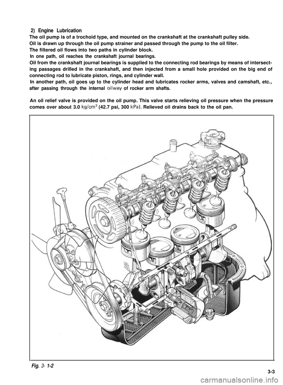
2) Engine Lubrication
The oil pump is of a trochoid type, and mounted on the crankshaft at the crankshaft pulley side.
Oil is drawn up through the oil pump strainer and passed through the pump to the oil filter.
The filtered oil flows into two paths in cylinder block.
In one path, oil reaches the crankshaft journal bearings.
Oil from the crankshaft journal bearings is supplied to the connecting rod bearings by means of intersect-
ing passages drilled in the crankshaft, and then injected from a small hole provided on the big end of
connecting rod to lubricate piston, rings, and cylinder wall.
In another path, oil goes up to the cylinder head and lubricates rocker arms, valves and camshaft, etc.,
after passing through the internal oilway of rocker arm shafts.
An oil relief valve is provided on the oil pump. This valve starts relieving oil pressure when the pressure
comes over about 3.0 kg/cm2 (42.7 psi, 300 kPa). Relieved oil drains back to the oil pan.
Fig. 3- 1-2
3-3
Page 61 of 962

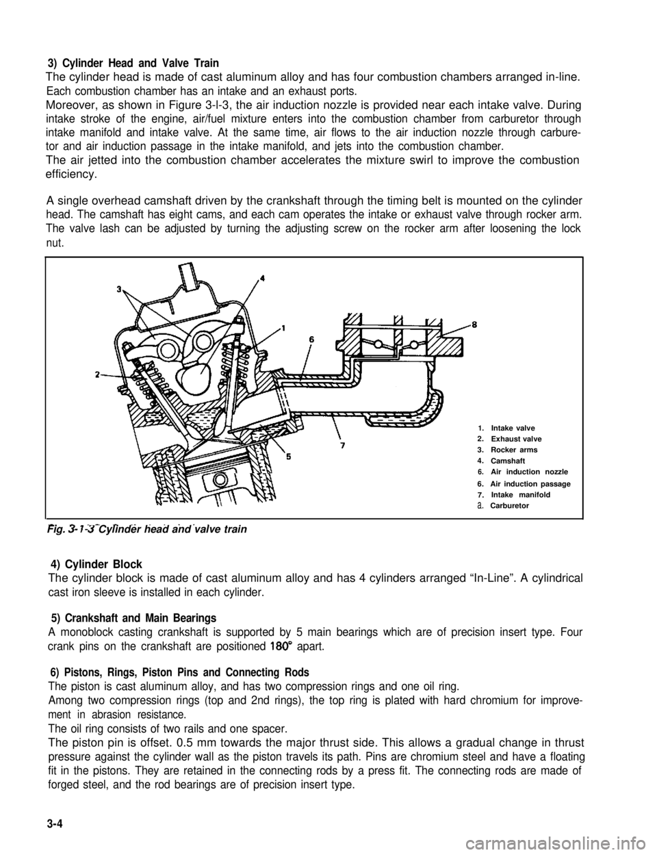
3) Cylinder Head and Valve Train
The cylinder head is made of cast aluminum alloy and has four combustion chambers arranged in-line.
Each combustion chamber has an intake and an exhaust ports.
Moreover, as shown in Figure 3-l-3, the air induction nozzle is provided near each intake valve. During
intake stroke of the engine, air/fuel mixture enters into the combustion chamber from carburetor through
intake manifold and intake valve. At the same time, air flows to the air induction nozzle through carbure-
tor and air induction passage in the intake manifold, and jets into the combustion chamber.
The air jetted into the combustion chamber accelerates the mixture swirl to improve the combustion
efficiency.
A single overhead camshaft driven by the crankshaft through the timing belt is mounted on the cylinder
head. The camshaft has eight cams, and each cam operates the intake or exhaust valve through rocker arm.
The valve lash can be adjusted by turning the adjusting screw on the rocker arm after loosening the lock
nut.
2-
1.Intake valve2.Exhaust valve
3.Rocker arms
4.Camshaft
6.Air induction nozzle
6.Air induction passage
7.Intake manifold
a.Carburetor
-. - _- - ._ . . . . .Fig. 3- 7-3 Cylinder head and valve train
4) Cylinder Block
The cylinder block is made of cast aluminum alloy and has 4 cylinders arranged “In-Line”. A cylindrical
cast iron sleeve is installed in each cylinder.
5) Crankshaft and Main Bearings
A monoblock casting crankshaft is supported by 5 main bearings which are of precision insert type. Four
crank pins on the crankshaft are positioned 180” apart.
6) Pistons, Rings, Piston Pins and Connecting Rods
The piston is cast aluminum alloy, and has two compression rings and one oil ring.
Among two compression rings (top and 2nd rings), the top ring is plated with hard chromium for improve-
ment in abrasion resistance.
The oil ring consists of two rails and one spacer.
The piston pin is offset. 0.5 mm towards the major thrust side. This allows a gradual change in thrust
pressure against the cylinder wall as the piston travels its path. Pins are chromium steel and have a floating
fit in the pistons. They are retained in the connecting rods by a press fit. The connecting rods are made of
forged steel, and the rod bearings are of precision insert type.
3-4