1987 SUZUKI GRAND VITARA low oil pressure
[x] Cancel search: low oil pressurePage 354 of 962
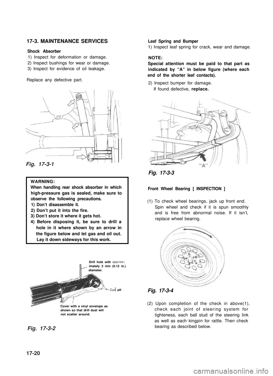
17-3. MAINTENANCE SERVICES
Shock Absorber
1) Inspect for deformation or damage.
2) Inspect bushings for wear or damage.
3) Inspect for evidence of oil leakage.
Replace any defective part.
WARNING:
When handling rear shock absorber in which
high-pressure gas is sealed, make sure to
observe the following precautions.
1) Don’t disassemble it.
2) Don’t put it into the fire.
3) Don’t store it where it gets hot.
4) Before disposing it, be sure to drill a
hole in it where shown by an arrow in
the figure below and let gas and oil out.
Lay it down sideways for this work.
Drill hole with approx-imately 3 mm (0.12 in.)diameter.
‘-cut off
Cover with a vinyl envelope asshown so that drill dust willnot scatter around.
Leaf Spring and Bumper
1) Inspect leaf spring for crack, wear and damage.
NOTE:
Special attention must be paid to that part as
indicated by “A” in below figure (where each
end of the shorter leaf contacts).
2) Inspect bumper for damage.
If found defective, replace.
Fig. 17-3-3
Front Wheel Bearing [ INSPECTION ]
(1) To check wheel bearings, jack up front end.
Spin wheel and check if it is spun smoothly
and is free from abnormal noise. If it isn’t,
replace wheel bearing.
Fig. 17-3-4
(2) Upon completion of the check in above(1),
check each joint of steering system for
tighteness, each ball stud of the steering link
as well as each kingpin for rattle. Then check
bearing as described below.
Fig. 17-3-1
Fig. 17-3-2
17-20
Page 392 of 962
![SUZUKI GRAND VITARA 1987 Service Repair Manual [Caliper OPERATION]
Single piston floating caliper type
The single piston floating caliper type brake is
employed in this model. One cylinder and one
piston are used for this type. (The cylinder is
co SUZUKI GRAND VITARA 1987 Service Repair Manual [Caliper OPERATION]
Single piston floating caliper type
The single piston floating caliper type brake is
employed in this model. One cylinder and one
piston are used for this type. (The cylinder is
co](/manual-img/20/57437/w960_57437-391.png)
[Caliper OPERATION]
Single piston floating caliper type
The single piston floating caliper type brake is
employed in this model. One cylinder and one
piston are used for this type. (The cylinder is
constructed as a monoblock with the caliper.)
Fluid pressure generated in the cylinder causes
the pad (1) on the piston side to press against
the disc. At the same time, the floating type
caliper body is moved to the right by the cylin-
der pressure, as shown in below figure, which
pulls pad (2) against the disc and so brakes the
wheel.
Caliper body
\Brake disc (rotor)
Fig. 19-6 - ’
The disc brake has no servo assistance as in drum
braking, and it is necessary to increase the work-
ing pressure of the piston and pad. For this pur-
pose, the wheel cylinder has a large bore. Even
only a little change in clearance between the disc
and pad has therefore a large influence on the
brake pedal stroke. It is necessary to have the
clearance adjusted to the minimum at all times,
by means of the piston (rubber) seal.
Piston seal (Rubber seal)Piston sealWinder (Rubber seal)
II
IPiston
Hydraulic pressure
“OFF“
Fig. 19-7
Clearance correction
Piston
Hydraulic pressure
“ON”
When oil pressure is applied to the piston, the
piston moves forward. The rubber seal, which
exerts considerable pressure against the piston,
moves with the cylinder. However, as a part of
the rubber seal has been fixed into a groove in
the cylinder, the shape of the rubber seal is dis-
torted toward internal end of the cylinder, as
shown in above figure. When pressure is taken
off from the foot brake pedal and fluid pressure
is released from the piston, a restoring force is
generated at the seal and pushes the piston back.
As the pads wear away and the clearance be-
tween the disc and pads becomes larger, the
piston moves a larger distance. The seal then
could change in shape further but, since the end
of the seal is fixed into the groove in the cylin-
der, the distortion is limited to the same amount
as previously described. The piston moves
further to cover the distance of clearance. The
piston returns by the same distance and the
rubber seal recovers its shape as described
above and thus the clearance between the disc
and pads are maintained in adjustment.
19-7
Cylinder
Page 396 of 962
![SUZUKI GRAND VITARA 1987 Service Repair Manual BOOSTER ASSEMBLY
[GENERAL DESCRIPTION]
The booster is located between the master cylinder and the brake pedal. It is so designed that the force
created when the brake pedal is depressed is mechanicall SUZUKI GRAND VITARA 1987 Service Repair Manual BOOSTER ASSEMBLY
[GENERAL DESCRIPTION]
The booster is located between the master cylinder and the brake pedal. It is so designed that the force
created when the brake pedal is depressed is mechanicall](/manual-img/20/57437/w960_57437-395.png)
BOOSTER ASSEMBLY
[GENERAL DESCRIPTION]
The booster is located between the master cylinder and the brake pedal. It is so designed that the force
created when the brake pedal is depressed is mechanically increased combined with the engine vacuum.
The booster has a diaphragm of 4 180 mm effective diameter. Its operation is described in the following pages.
NOTE:
Use all components included in repair kits to service this booster. Lubricate rubber parts, where indicat-
ed, with silicone grease provided in kits. The torque values specified are for dry, unlubricated fasteners.
If any hydraulic component is removed or brake line disconnected, bleed the brake system.
Never lubricate any hydraulic component with silicone grease.
11.Vacuum check valve11.No. 2 body oil seal
2.3.Grommet12.Booster air valve assembly
Booster No. 1 body13.Air cleanerseparator
4. PistonRod14.Air cleaner element
5. Reaction disc 15.Body boot
6.Booster piston returnspring16.Nut7. Valve stopper key17.Bracket
8.Booster piston18.Push rod clevis
9. Diaphragm19.Pressure plate
10.Booster No. 2 body
Fig. 19-12
19-11
Page 427 of 962
19-8. MAINTENANCE SERVICE
ROAD TESTING BRAKES
Brakes should be tested on dry, clean, smooth
and reasonably level roadway which is not
crowned. Road test brakes by making brake
applications with both light and heavy pedal
forces at various speeds to determine if the car
stops evenly and effectively.
Also drive car to see if it leads to one side or the
other without brake application. If it does,
check tire pressure, front end alignment and
front suspension attachments for looseness.
See diagnosis chart for other causes.
BRAKE FLUID LEAKS
Check master cylinder fluid levels. While a slight
drop in reservoir level does result from normal
lining wear, an abnormally low level indicates a
leak in the system.In such a case, check the
entire brake system for leakage. If even a slight
evidence of leakage is noted, the cause should be
corrected or defective parts should be replaced.
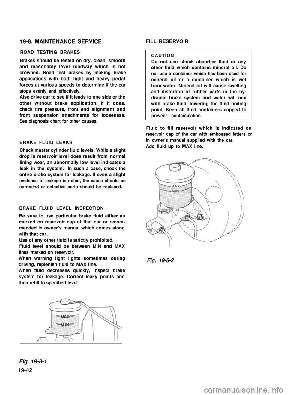
BRAKE FLUID LEVEL INSPECTION
Be sure to use particular brake fluid either as
marked on reservoir cap of that car or recom-
mended in owner’s manual which comes along
with that car.
Use of any other fluid is strictly prohibited.
Fluid level should be between MIN and MAX
lines marked on reservoir.
When warning light lights sometimes during
driving, replenish fluid to MAX line.
When fluid decreases quickly, inspect brake
system for leakage. Correct leaky points and
then refill to specified level.
FILL RESERVOIR
CAUTION:
Do not use shock absorber fluid or any
other fluid which contains mineral oil. Do
not use a container which has been used for
mineral oil or a container which is wet
from water. Mineral oil will cause swelling
and distortion of rubber parts in the hy-
draulic brake system and water will mix
with brake fluid, lowering the fluid boiling
point. Keep all fluid containers capped to
prevent contamination.
Fluid to fill reservoir which is indicated on
reservoir cap of the car with embossed letters or
in owner’s manual supplied with the car.
Add fluid up to MAX line.
Fig. 19-8-2
Fig. 19-8-1
19-42
Page 446 of 962
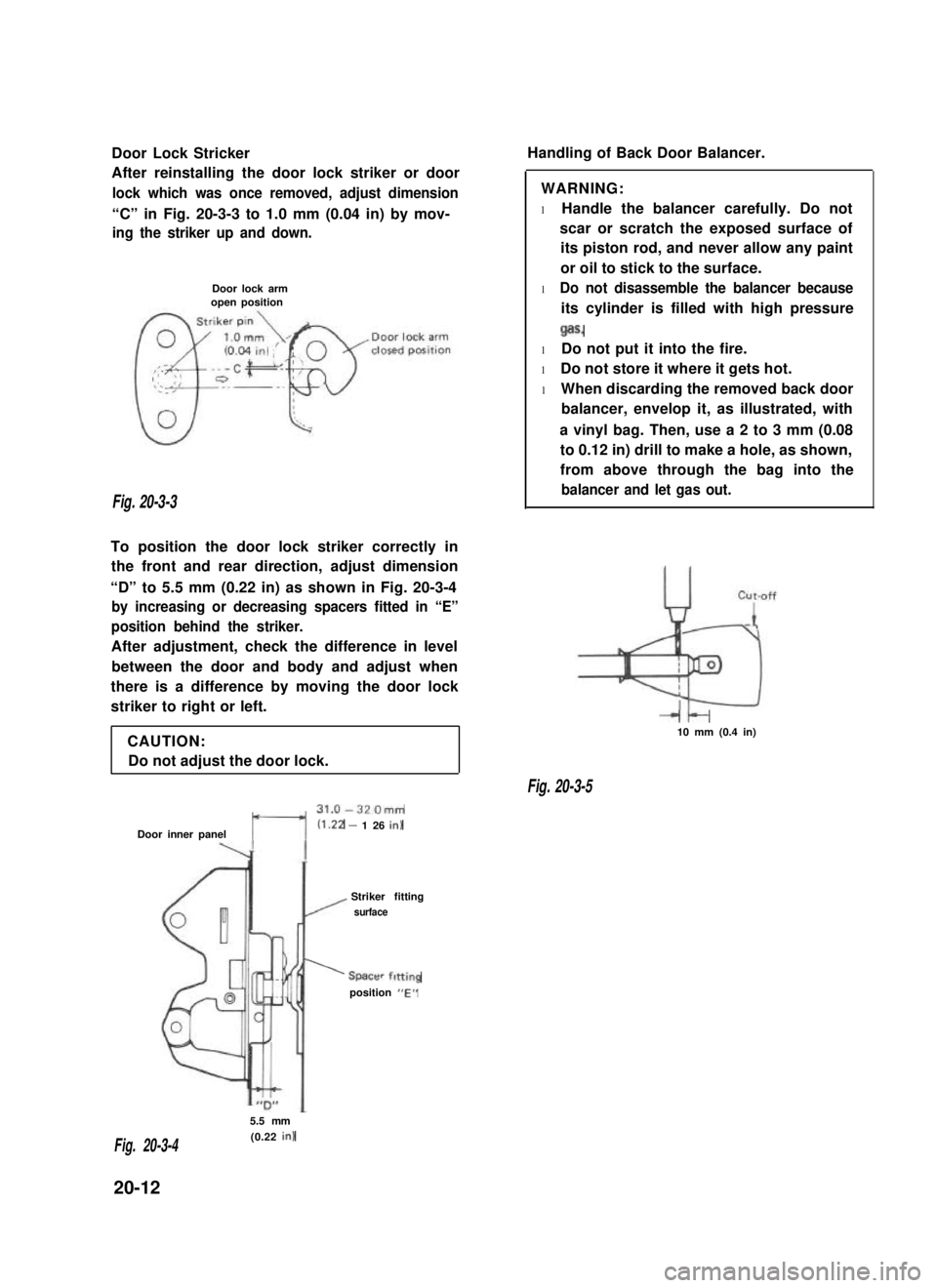
Door Lock Stricker
After reinstalling the door lock striker or door
lock which was once removed, adjust dimension
“C” in Fig. 20-3-3 to 1.0 mm (0.04 in) by mov-
ing the striker up and down.
Door lock armopen position
Fig. 20-3-3
To position the door lock striker correctly in
the front and rear direction, adjust dimension
“D” to 5.5 mm (0.22 in) as shown in Fig. 20-3-4
by increasing or decreasing spacers fitted in “E”
position behind the striker.
After adjustment, check the difference in level
between the door and body and adjust when
there is a difference by moving the door lock
striker to right or left.
CAUTION:
Do not adjust the door lock.
t---l
31.0-320mm
Door inner panel(1.22 - 1 26 in)
Striker fitting
/ surface
’ Spacer fitting
position “E”
Handling of Back Door Balancer.
WARNING:
l Handle the balancer carefully. Do not
scar or scratch the exposed surface of
its piston rod, and never allow any paint
or oil to stick to the surface.
l Do not disassemble the balancer because
its cylinder is filled with high pressure
Qas.
l Do not put it into the fire.
l Do not store it where it gets hot.
l When discarding the removed back door
balancer, envelop it, as illustrated, with
a vinyl bag. Then, use a 2 to 3 mm (0.08
to 0.12 in) drill to make a hole, as shown,
from above through the bag into the
balancer and let gas out.
It-10 mm (0.4 in)
Fig. 20-3-5
5.5 mm
(0.22 in)Fig. 20-3-4
20-12
Page 450 of 962
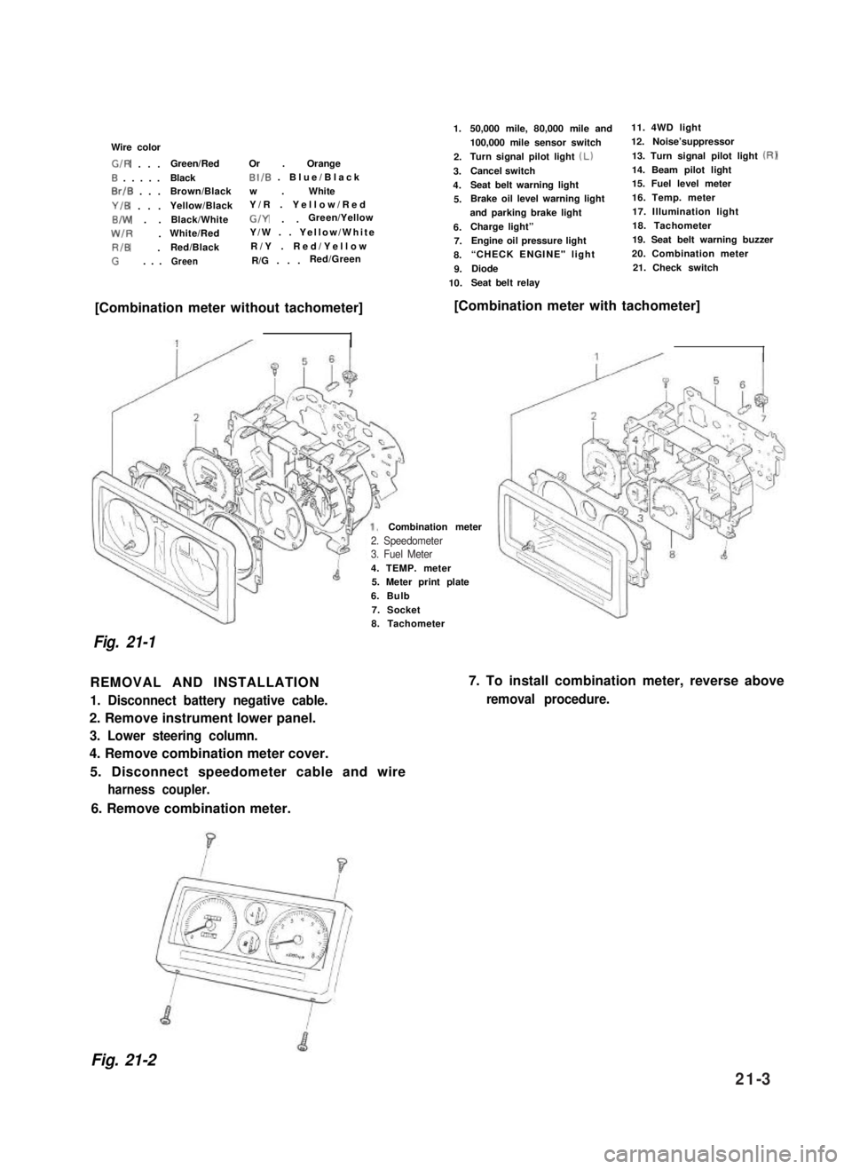
Wire color
G/R . . .Green/RedOr . Orange
0 . . . . .BlackBI/B . Blue/Black
0rlB . . .Brown/Blackw . White
Y/B . . .Yellow/BlackY/R . Yellow/Red
B/W . .Black/WhiteG/Y . .Green/Yellow
W/R .White/RedY/W . . Yellow/White
RIB .Red/BlackR/Y . Red/Yellow
G. . .GreenR/G . . .Red/Green
1.
2.
3.
4.
5.
6.7.
8.
9.
10.
50,000 mile, 80,000 mile and11. 4WD light
100,000 mile sensor switch12. Noise’suppressor
Turn signal pilot light (Lb13. Turn signal pilot light (RI
Cancel switch14. Beam pilot light
Seat belt warning light15. Fuel level meter
Brake oil level warning light16. Temp. meter
and parking brake light17. Illumination light
Charge light”18. Tachometer
Engine oil pressure light19. Seat belt warning buzzer
“CHECK ENGINE" light 20. Combination meter
Diode21. Check switch
Seat belt relay
[Combination meter without tachometer][Combination meter with tachometer]
4. TEMP. meter5. Meter print plate
6. Bulb
7. Socket
Combination meter
Fig. 21-1
8. Tachometer
REMOVAL AND INSTALLATION
1. Disconnect battery negative cable.
2. Remove instrument lower panel.
3. Lower steering column.
4. Remove combination meter cover.
5. Disconnect speedometer cable and wire
harness coupler.
7. To install combination meter, reverse above
removal procedure.
6. Remove combination meter.
Fig. 21-2
2. Speedometer3. Fuel Meter
21-3
Page 461 of 962
![SUZUKI GRAND VITARA 1987 Service Repair Manual INSPECTION21-8. OIL PRESSURE LAMP
[Brake fluid level switch]
Use ohmmeter to check switch for resistance
and continuity.
If found defective, replace switch.
The oil pressure lamp circuit consists of t SUZUKI GRAND VITARA 1987 Service Repair Manual INSPECTION21-8. OIL PRESSURE LAMP
[Brake fluid level switch]
Use ohmmeter to check switch for resistance
and continuity.
If found defective, replace switch.
The oil pressure lamp circuit consists of t](/manual-img/20/57437/w960_57437-460.png)
INSPECTION21-8. OIL PRESSURE LAMP
[Brake fluid level switch]
Use ohmmeter to check switch for resistance
and continuity.
If found defective, replace switch.
The oil pressure lamp circuit consists of the oil
pressure switch installed to the cylinder block
and the lamp (warning lamp) inside the combi-
nation meter.
The oil pressure switch so operates that it is
switched OFF when oil pressure is produced by
the started engine and then fed to switch.
Fig. 21-23W/R : White/Red
6 : Black
RI0 : RedlBlack
1. Battery
2. Main switch
3. Fuse4. Oil pressure lamp
6. Oil pressure switch
B/El : Black/Blue
B/W : Black/White
Y/0 : Yellow/Black
W/Y : White/Yellow
Fig. 21-24
INSPECTION
[Oil pressure switch]
Use a ohmmeter to check the switch continuity.
During engine
Running
No continuity
obtained (- 52 1
IAt Engine StopContinuity obtained
(052)
1. To wiring harness
2. Cylinder block
Fig. 21-2521-14
Page 464 of 962
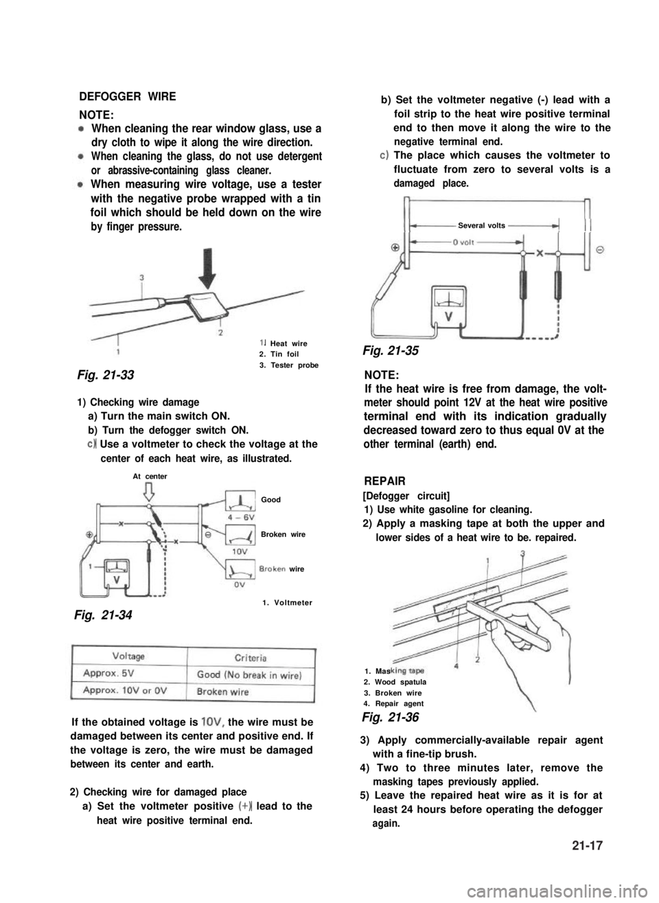
DEFOGGER WIRE
NOTE:
When cleaning the rear window glass, use a
dry cloth to wipe it along the wire direction.
When cleaning the glass, do not use detergent
or abrassive-containing glass cleaner.
When measuring wire voltage, use a tester
with the negative probe wrapped with a tin
foil which should be held down on the wire
by finger pressure.
1. Heat wire2. Tin foil
3. Tester probe
Fig. 21-33 NOTE:
1) Checking wire damage
a) Turn the main switch ON.
b) Turn the defogger switch ON.
c) Use a voltmeter to check the voltage at the
center of each heat wire, as illustrated.
At center
Good
Broken wire
B.roken wire
1. Voltmeter
Fig. 21-34
If the obtained voltage is lOV, the wire must be
damaged between its center and positive end. If
the voltage is zero, the wire must be damaged
between its center and earth.
2) Checking wire for damaged place
a) Set the voltmeter positive (+) lead to the
heat wire positive terminal end.
b) Set the voltmeter negative (-) lead with a
foil strip to the heat wire positive terminal
end to then move it along the wire to the
negative terminal end.
c) The place which causes the voltmeter to
fluctuate from zero to several volts is a
damaged place.
Several volts -_(( (
Fig. 21-35
If the heat wire is free from damage, the volt-
meter should point 12V at the heat wire positive
terminal end with its indication gradually
decreased toward zero to thus equal 0V at the
other terminal (earth) end.
REPAIR
[Defogger circuit]
1) Use white gasoline for cleaning.
2) Apply a masking tape at both the upper and
lower sides of a heat wire to be. repaired.
1. Mas
2. Wood spatula
3. Broken wire4. Repair agent
Fig. 21-36
3) Apply commercially-available repair agent
with a fine-tip brush.
4) Two to three minutes later, remove the
masking tapes previously applied.
5) Leave the repaired heat wire as it is for at
least 24 hours before operating the defogger
again.
21-17