1987 SUZUKI GRAND VITARA diagram
[x] Cancel search: diagramPage 206 of 962
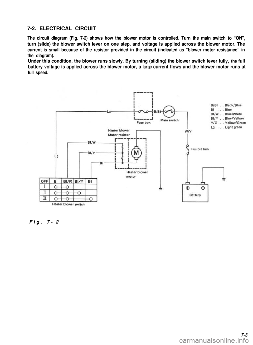
7-2. ELECTRICAL CIRCUIT
The circuit diagram (Fig. 7-2) shows how the blower motor is controlled. Turn the main switch to “ON”,
turn (slide) the blower switch lever on one step, and voltage is applied across the blower motor. The
current is small because of the resistor provided in the circuit (indicated as “blower motor resistance” in
the diagram).
Under this condition, the blower runs slowly. By turning (sliding) the blower switch lever fully, the full
battery voltage is applied across the blower motor, a large current flows and the blower motor runs at
full speed.
r-mm-1
ri
BlBl . .Black/Blue
LaBI . . . Blue
BIIW . .Blue/White
BUY . .Blue/Yellow
Y/G . .Yellow/Green
Heater blowerLa . . . Light green
Motor resistor
,,w~
motor
Heater blower switch
Fusible link
I
Fig. 7-2
7-3
Page 212 of 962
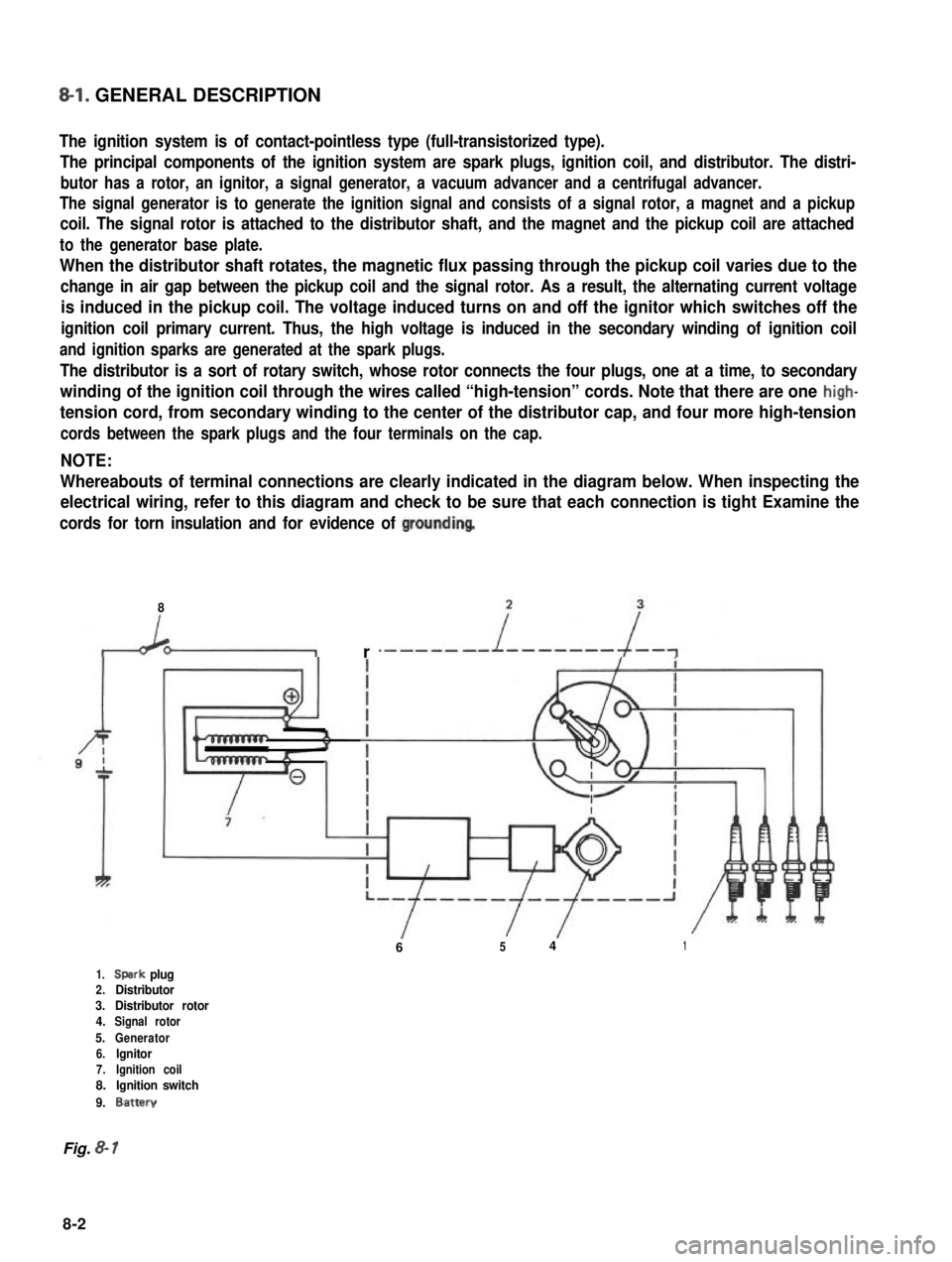
8-l. GENERAL DESCRIPTION
The ignition system is of contact-pointless type (full-transistorized type).
The principal components of the ignition system are spark plugs, ignition coil, and distributor. The distri-
butor has a rotor, an ignitor, a signal generator, a vacuum advancer and a centrifugal advancer.
The signal generator is to generate the ignition signal and consists of a signal rotor, a magnet and a pickup
coil. The signal rotor is attached to the distributor shaft, and the magnet and the pickup coil are attached
to the generator base plate.
When the distributor shaft rotates, the magnetic flux passing through the pickup coil varies due to the
change in air gap between the pickup coil and the signal rotor. As a result, the alternating current voltage
is induced in the pickup coil. The voltage induced turns on and off the ignitor which switches off the
ignition coil primary current. Thus, the high voltage is induced in the secondary winding of ignition coil
and ignition sparks are generated at the spark plugs.
The distributor is a sort of rotary switch, whose rotor connects the four plugs, one at a time, to secondary
winding of the ignition coil through the wires called “high-tension” cords. Note that there are one high-
tension cord, from secondary winding to the center of the distributor cap, and four more high-tension
cords between the spark plugs and the four terminals on the cap.
NOTE:
Whereabouts of terminal connections are clearly indicated in the diagram below. When inspecting the
electrical wiring, refer to this diagram and check to be sure that each connection is tight Examine the
cords for torn insulation and for evidence of groundinq
8
r
6541
1.Spark plug2.Distributor3.Distributor rotor4.Signal rotor
5.Generator6.lgnitor7.Ignition coil8.Ignition switch
9.Battery
Fig. 8- 1
8-2
Page 236 of 962
The alternator features a solid state regulator
that is mounted inside the alternator. All regula-
tor components are enclosed into a solid mold,
and this unit along with the brush holder assemb-
ly is attached to the slip ring end frame. The
regulator voltage setting cannot be adjusted.
The alternator rotor bearings contain enough
grease to eliminate the need for periodic lubri-
cation. Two brushes carry current through the
two slip rings to the field coil mounted on the
rotor, and under normal conditions will provide
long period of attention-free service.
The stator windings are assembled on the inside
of a laminated core that forms part of the
alternator frame. A rectifier bridge connected
to the stator windings contains six diodes,
and electrically changes the stator A.C. voltages
to a D.C. voltage which appears at the generator
output terminal.
The neutral diodes serve to convert the voltage
fluctuation at the neutral point to direct current
for increasing the alternator output.
A condenser mounted in the end frame protects
the diodes from high voltages and suppresses
radio noise.
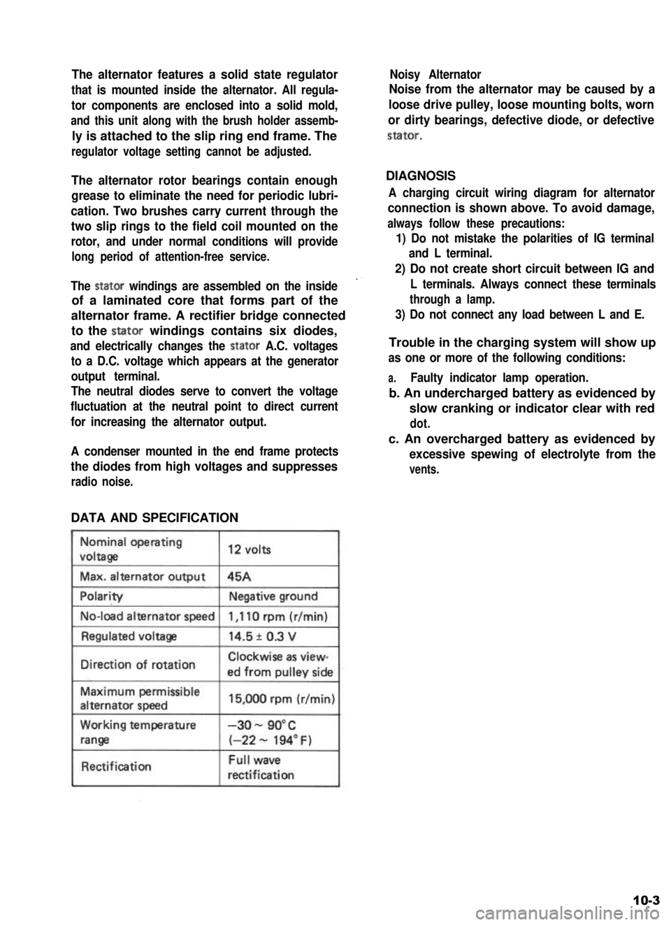
DATA AND SPECIFICATION
Nominal operating
voltaga
Max. alternator output
12 volts
45A
No-load alternator speed
IDirection of rotationClockwise as view-
ed from oullev side
Maximum permissible
alternator speed
Working temperature
range
Rectification
15,000 rpm (r/min)
-3o- 90°C
(-22 - 194” F)
Full wave
rectification
Noisy Alternator
Noise from the alternator may be caused by a
loose drive pulley, loose mounting bolts, worn
or dirty bearings, defective diode, or defective
stator.
DIAGNOSIS
A charging circuit wiring diagram for alternator
connection is shown above. To avoid damage,
always follow these precautions:
1) Do not mistake the polarities of IG terminal
and L terminal.
2) Do not create short circuit between IG and
L terminals. Always connect these terminals
through a lamp.
3) Do not connect any load between L and E.
Trouble in the charging system will show up
as one or more of the following conditions:
a.Faulty indicator lamp operation.
b. An undercharged battery as evidenced by
slow cranking or indicator clear with red
dot.
c. An overcharged battery as evidenced by
excessive spewing of electrolyte from the
vents.
10-3
Page 237 of 962
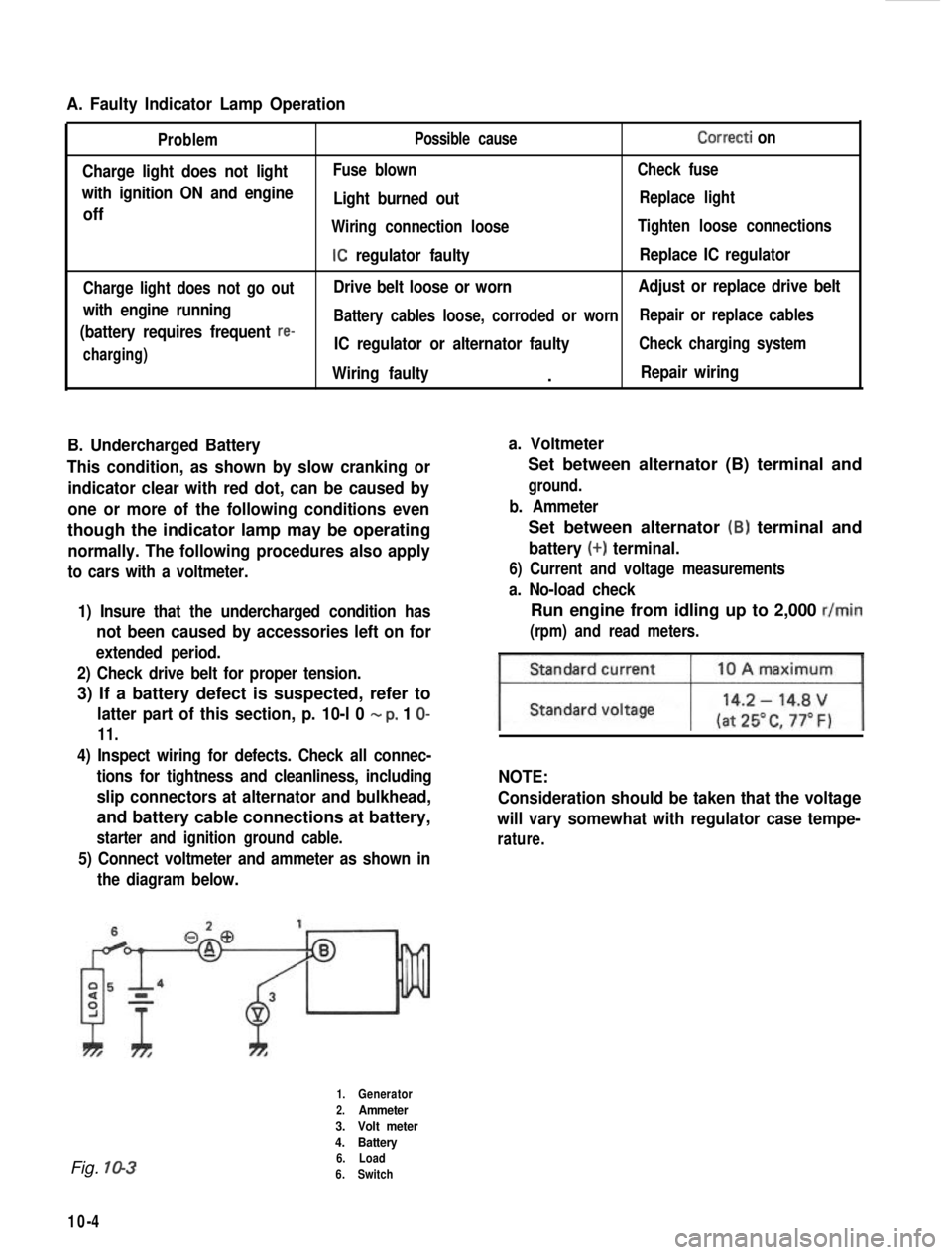
A. Faulty Indicator Lamp Operation
Problem
Charge light does not light
with ignition ON and engine
off
Charge light does not go out
with engine running
(battery requires frequent
re-
charging) Possible cause
Correcti on
Fuse blown
Check fuse
Light burned outReplace light
Wiring connection loose Tighten loose connections
IC regulator faultyReplace IC regulator
Drive belt loose or worn Adjust or replace drive belt
Battery cables loose, corroded or worn Repair or replace cables
IC regulator or alternator faultyCheck charging system
Wiring faulty.Repair wiring
B. Undercharged Battery a. Voltmeter
This condition, as shown by slow cranking or indicator clear with red dot, can be caused by
one or more of the following conditions even
though the indicator lamp may be operating
normally. The following procedures also apply
to cars with a voltmeter.
1) Insure that the undercharged condition has
not been caused by accessories left on for
extended period.
2) Check drive belt for proper tension.
3) If a battery defect is suspected, refer to
latter part of this section, p. 10-l 0 - p, 1 O-
11.
4) Inspect wiring for defects. Check all connec- tions for tightness and cleanliness, including
slip connectors at alternator and bulkhead,
and battery cable connections at battery,
starter and ignition ground cable.
5) Connect voltmeter and ammeter as shown inthe diagram below.
Set between alternator (B) terminal and
ground.
b. Ammeter
Set between alternator (B) terminal and
battery (+) terminal.
6) Current and voltage measurements
a. No-load check
Run engine from idling up to 2,000 r/min
(rpm) and read meters.
NOTE:
Consideration should be taken that the voltage
will vary somewhat with regulator case tempe-
rature.
Fig. 10-3
10-4
1.Generator
2.Ammeter
3. Volt meter
4. Battery
6. Load
6. Switch
Page 443 of 962
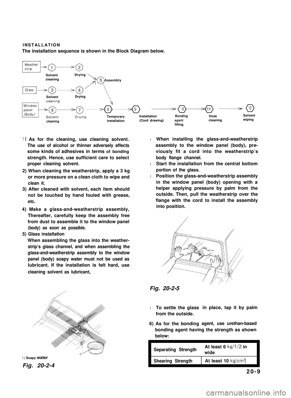
INSTALLATION
The installation sequence is shown in the Block Diagram below.
SolventcleaningDrying\rr05 Assembly
SolventDrying
4
-8-9F10-11B12
TemporaryinstallationInstallation(Cord drawing)Bondingagentfilling
Oozecleaning
Solventwipingcleaning
1) As for the cleaning, use cleaning solvent.
The use of alcohol or thinner adversely affects
some kinds of adhesives in terms of bonding
strength. Hence, use sufficient care to select
proper cleaning solvent.
2) When cleaning the weatherstrip, apply a 3 kg
or more pressure on a clean cloth to wipe and
clean it.
3) After cleaned with solvent, each item should
not be touched by hand fouled with grease,
etc.
4) Make a glass-and-weatherstrip assembly,
Thereafter, carefully keep the assembly free
from dust to assemble it to the window panel
(body) as soon as possible.
5) Glass installation
When assembling the glass into the weather-
strip’s glass channel, and when assembling the
glass-and-weatherstrip assembly to the window
panel (body) soapy water must not be used as
lubricant. If the installation is felt hard, use
cleaning solvent as lubricant,
1, Soapy water
Fig. 20-2-4
l When installing the glass-and-weatherstrip
assembly to the window panel (body), pre-
viously fit a cord into the weatherstrip’s
body flange channel.
l Start the installation from the central bottom
portion of the glass.
l Position the glass-and-weatherstrip assembly
in the window panel (body) opening with a
helper applying pressure by palm from the
outside. Then, pull the weatherstrip over the
flange with the cord to install the assembly
into position.
Fig. 20-2-5
l To settle the glass
from the outside.
in place, tap it by palm
6) As for the bondingagent, use urethan-based
bonding agent having the strength as shown
below:
ISeparating StrengthAt least 6 kg/l/2 in
wideI
Shearing StrengthAt least 10 kg/cm2I
20-9
Page 448 of 962
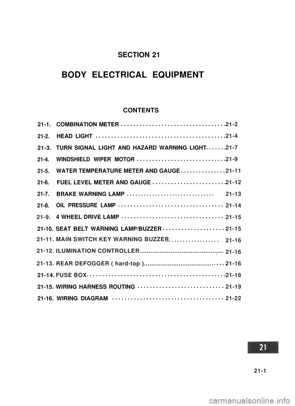
21-1.COMBINATION METER..................................
21-2.HEAD LIGHT..........................................
21-3.TURN SIGNAL LIGHT AND HAZARD WARNING LIGHT.......
21-4.WINDSHIELD WIPER MOTOR.............................
21-5.WATER TEMPERATURE METER AND GAUGE...............
21-6.FUEL LEVEL METER AND GAUGE........................
21-7.BRAKE WARNING LAMP ...............................
21-8.OIL PRESSURE LAMP..................................
4 WHEEL DRIVE LAMP.................................
21-10. SEAT BELT WARNING LAMP/BUZZER.....................
...................
...~I-I
.....
21-14. .............................................
21-15. WIRING HARNESS ROUTING............................
21-16. WIRING DIAGRAM....................................
SECTION 21
BODY ELECTRICAL EQUIPMENT
CONTENTS
21-9.
21-11. MAIN SWITCH KEY WARNING BUZZER
21-12. ILUMINATION CONTROLLER..............................................
21-13. REAR DEFOGGER ( hard-top )......................................
FUSE BOX
21-2
21-4
21-7
21-9
21-11
21-12
21-13
21-14
21-15
21-15
21-16
21-16
21-16
21-18
21-19
21-22
21-1
Page 460 of 962
![SUZUKI GRAND VITARA 1987 Service Repair Manual [Gauge unit]21-7. BRAKE WARNING LAMP
Use ohmmeter to confirm that level gauge unit
changes in resistance with change of the float
position. Float position-to-resistance relation-
ship can be plotted i SUZUKI GRAND VITARA 1987 Service Repair Manual [Gauge unit]21-7. BRAKE WARNING LAMP
Use ohmmeter to confirm that level gauge unit
changes in resistance with change of the float
position. Float position-to-resistance relation-
ship can be plotted i](/manual-img/20/57437/w960_57437-459.png)
[Gauge unit]21-7. BRAKE WARNING LAMP
Use ohmmeter to confirm that level gauge unit
changes in resistance with change of the float
position. Float position-to-resistance relation-
ship can be plotted in a graph as shown below.
The brake warning lamp system consists of the
brake fluid level switch installed to the master
cylinder reservoir and the lamp inside the
combination meter.
This circuit includes a parking brake switch
which gives a warning for unreleased parking
brake.
F-E
Fig. 21-20 Resistance-Fuel Level Relationship
Fig. 21-21
F : Full
E : Empty
OPERATION
Brake fluid level warning lamp circuit consists of
brake fluid level switch installed in master
cylinder reservoir, brake fluid level warning lamp
in gage cluster and check relay.
Also, this circuit is additionally provided with
parking brake switch which warns that parking
brake is applied.when engine is stopped,
warning lamp comes on, if ignition switch is
turned ON and parking brake is applied.
For bulb check, warning lamp comes on briefly
during engine starting regardless of brake fluid
level position and parking brake operation.
Because point of check relay is closed.
After engine is started, release parking brake.
If lamp gose off, brake fluid level is adequate.
When warning lamp dose not operate, use circuit
diagram as reference to check bulb, wiring, etc.
r---i
check relayl-2-l
B/Y : Black/Yellow1. Fluid level switch
R/B : Red/Black2. Warning lamp
B: Black3. Parking brake switch
B/W : Black/White4. Main switch
B/BI : Black/Blue5. Battery
Fig. 27-22
21-13
Page 462 of 962
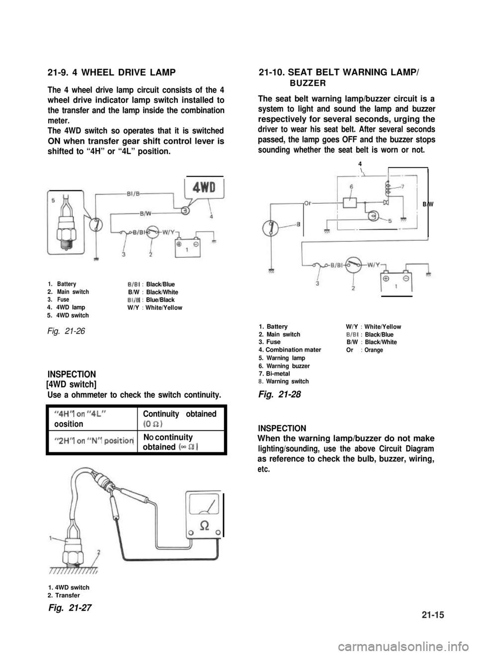
21-9. 4 WHEEL DRIVE LAMP21-10. SEAT BELT WARNING LAMP/
BUZZERThe 4 wheel drive lamp circuit consists of the 4
wheel drive indicator lamp switch installed to
the transfer and the lamp inside the combination
meter.
The 4WD switch so operates that it is switched
ON when transfer gear shift control lever is
shifted to “4H” or “4L” position.
The seat belt warning lamp/buzzer circuit is a
system to light and sound the lamp and buzzer
respectively for several seconds, urging the
driver to wear his seat belt. After several seconds
passed, the lamp goes OFF and the buzzer stops
sounding whether the seat belt is worn or not.
1.BatteryB/B1:Black/Blue2.Main switchB/W:Black/White3.FuseBI/B:Blue/Black4.4WD lampW/Y:White/Yellow5.4WD switch
Fig. 21-26
INSPECTION
[4WD switch]
Use a ohmmeter to check the switch continuity.
I
“4H” or “4L”Continuity obtained
oosition(052)I
I
#,2HM or ##N## positionNO continuity
obtained (- 52 1I
CL-
01
8
4\II
B/W
1. Battery
2. Main switch3. Fuse
4. Combination mater
5. Warning lamp
6. Warning buzzer7. Bi-metal8. Warning switch
W/Y:White/Yellow
BIBI:Black/BlueB/W:Black/White
Or:Orange
Fig. 21-28
INSPECTION
When the warning lamp/buzzer do not make
lighting/sounding, use the above Circuit Diagram
as reference to check the bulb, buzzer, wiring,
etc.
1. 4WD switch
2. Transfer
Fig. 21-2721-15