Page 76 of 962

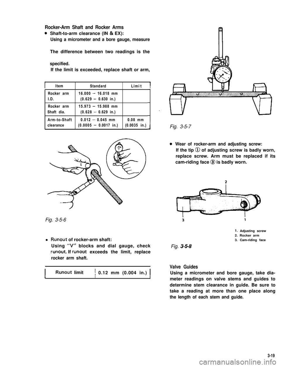
Rocker-Arm Shaft and Rocker Arms
0Shaft-to-arm clearance (IN & EX):
Using a micrometer and a bore gauge, measure
The difference between two readings is the
specified.
If the limit is exceeded, replace shaft or arm,
IItemStandardLimitI
Rocker arm16.000 - 16.018 mm
I.D.(0.629 - 0.630 in.)
Rocker arm15.973 - 15.988 mm
Shaft dia.(0.628 - 0.629 in.)
Arm-to-Shaft0.012 - 0.045 mm0.08 mm
clearance(0.0005 - 0.0017 in.)(0.0035 in.)
Fig. 3-5-6
l Runout of rocker-arm shaft:
Using “V” blocks and dial gauge, check
runout. If runout exceeds the limit, replace
rocker arm shaft.
IRunout limitI1 0.12 mm (0.004 in.) 1II
Fig. 3-5-7
0Wear of rocker-arm and adjusting screw:
If the tip @ of adjusting screw is badly worn,
replace screw. Arm must be replaced if its
cam-riding face @I is badly worn.
1. Adjusting screw2. Rocker arm3. Cam-riding face
Fig. 3-5-8
Valve Guides
Using a micrometer and bore gauge, take dia-
meter readings on valve stems and guides to
determine stem clearance in guide. Be sure to
take a reading at more than one place along
the length of each stem and guide.
3-19
Page 85 of 962
Fig. 3-5-19 Contactpattern @ uniform in width
Valve Springs
l Referring to the criterion-data given below,
check to be sure that each spring is in sound
condition, free of any evidence of breakage or
weakening. Remember, weakenedvalve springs
can be the cause of chatter, not to mention
the possibility of reducing power output due
to gas leakage caused by decreased seating
Valve springfor 41.5 mmfor 41.5 mm
preload(54.7 - 64.3 lb/(50.2 lb/
1.63 in.)1.63 in.)
Fig. 3-5-21 Measuring spring preload
l Spring squareness:
Use a square and surface plate to check each
spring for squareness in terms of clearance
between the end of valve spring and square.
Valve springs found to exhibit a larger clea-
rance than specified limit must be replaced.
Valve springs
squareness limit2.0 mm (0.079 in.)
Fig. 3-5-22 Measuring spring squareness
Fig. 3-5-20 Measuring free length of spring
3-23
Page 87 of 962

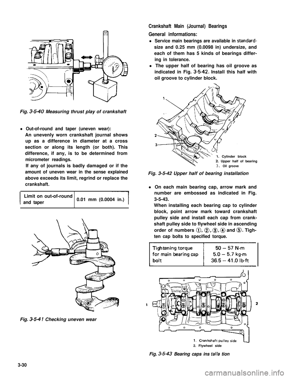
Crankshaft Main (Journal) Bearings
General informations:
l Service main bearings are available in standard-
size and 0.25 mm (0.0098 in) undersize, and
each of them has 5 kinds of bearings differ-
ing in tolerance.
l The upper half of bearing has oil groove as
indicated in Fig. 3~5-42. Install this half with
oil groove to cylinder block.
Fig. 3-5-40 Measuring thrust play of crankshaft
l Out-of-round and taper (uneven wear):
An unevenly worn crankshaft journal shows
up as a difference in diameter at a cross
section or along its length (or both). This
difference, if any, is to be determined from
micrometer readings.
If any of journals is badly damaged or if the
amount of uneven wear in the sense explained
above exceeds its limit, regrind or replace the
crankshaft.
I
Limit on out-of-round
and taper0.01 mm (0.0004 in.)
Fig. 3-5-4 1 Checking uneven wear
1. Cylinder block2. Upper half of bearing
3. Oil groove
Fig. 3-5-42 Upper half of bearing installation
l On each main bearing cap, arrow mark and
number are embossed as indicated in Fig.
3-5-43.
When installing each bearing cap to cylinder
block, point arrow mark toward crankshaft
pulley side and install each cap from crank-
shaft pulley side to flywheel side in ascending
order of numbers @,a, 0, @ and 0. Tigh-
ten cap bolts to specified torque.
3
2. Flywheel side
Fig. 3-5-43 Bearing caps ins talla tion
3-30
Page 225 of 962
9-2. SPECIFICATIONS
Voltage12 volts
output0.9 kW
Rating30 seconds
Direction of rotationClockwise as viewed from pinion side
Brush length17 mm (0.67 in.)
Number of pinion teeth
No-load characteristic
6
60 A maximum at 11.5 volts, 6,600 r/min minimum
ILoad characteristic150 A maximum at 9 volts and 0.29 kg-m torque,
1.900 r/min minimum,
500A maximum at-5 volts, 1.15 kg-m minimum
8 volts maximum
Locked rotor current
Magnetic switch operating voltage
9-4
Page 229 of 962
Ground test
Check commutator and armature coil core. If
there is continuity, armature is grounded and
must be replaced.
Fig. 915
Open circuit test
Check for continuity between segments. If
there is no continuity at any test point, there is
an open circuit and armature must be replaced.
Fig. 9 16
2) Inspect Field Coil
Open circuit test
Check for continuity between brush and bare
surface. If there is continuity, field windings are
grounded. The field coil must be replaced.
Fig. 917
3) Inspect Brush
Check brushes for wear. If below limit, replace
brush.
Brush length~~
Fig. 918
9-8
Page 242 of 962
Brush and Brush holder
Check each brush for wear by measuring its
length as shown. If brush is found worn down to
service limit, replace brush with holder.
Brush lengthStandardService limit
11 mm (0.43 in)5 mm (0.20 in)
Fig. lo-16
Rectifier
Using an ohmmeter, check continuity between
“B” terminal and ground.
Put one tester lead to terminal “B” and the
other lead to ground; then swap two leads. Of
two tester indications, one should be about
10 ohms, meaning continuity, and the other
should be infinity (non continuity).
If not, replace rectifier assembly.
Condenser
Check condenser capacity in regulator.
Fig. 10-18
ICondenser capacity0.5 /JF
ASSEMBLY
Reverse disassembly procedure, using care on
following points.
1) Use a press when forcing bearing into rotor
shaft or drive end frame.
Fig. lo-19
e: Battery terminal
E: Earth
Fig. 10-17
2) Alternator pulley tightening torque.
Tightening torque
50-65N-m15.0-6.5kpm137-47lb-ft
10-9
Page 275 of 962

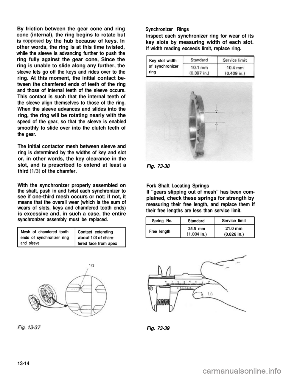
By friction between the gear cone and ring
cone (internal), the ring begins to rotate but
is copposed by the hub because of keys. In
other words, the ring is at this time twisted,
while the sleeve is advancing further to push the
ring fully against the gear cone, Since the
ring is unable to slide along any further, the
sleeve lets go off the keys and rides over to the
ring. At this moment, the initial contact be-
tween the chamfered ends of teeth of the ring
and those of internal teeth of the sleeve occurs.
This contact is such that the internal teeth of
the sleeve align themselves to those of the ring.
When the sleeve advances and slides into the
ring, the ring will be rotating nearly with the
speed of the gear, so that the sleeve is enabled
smoothly to slide over into the clutch teeth of
the gear.
The initial contactor mesh between sleeve and
ring is determined by the widths of key and slot
or, in other words, the key clearance in the
slot, and is prescribed to extend at least a
third (l/3) of the chamfer.
With the synchronizer properly assembled on
the shaft, push in and twist each synchronizer to
see if one-third mesh occurs or not; if not, it
means that the overall wear (which is the sum of
wears of slots, keys and chamfered tooth ends)
is excessive and, in such a case, the entire
synchronizer assembly must be replaced.
1Mesh of chamfered toothContact extending
ends of synchronizer ringabout l/3 of cham-
and sleevefered face from apex
l/3
Synchronizer Rings
Inspect each synchronizer ring for wear of its
key slots by measuring width of each slot.
If width reading exceeds limit, replace ring.
Key slot width
of synchronizer
ring
Fig. 73-38
Fork Shaft Locating Springs
If “gears slipping out of mesh” has been com-
plained, check these springs for strength by
measuring their free length, and replace them if
their free lengths are less than service limit.
Spring No.
Free length
StandardService limit
25.5 mm21.0 mm
(I.004 in.)(0.826 in.)
Fig. 73-39
13-14
Page 299 of 962
11) When input shaft is removed, front bearing
may be left in case. In this case, after remov-
ing oil seal and circlip, bearing can be taken
out of case by using bearing installer (special
tool).
Bearing installer @ : (09913-75810)
Fig. 14-33
Transfer Rear Case
1) When center case and rear case are separated,
input shaft may be left in rear case. In this
case, remove input shaft from rear case by
hammering thick part of case with a plastic
hammer.
Fig. 14-34
14-7. INSPECTION OF COMPONENTS
Gear Teeth
Inspect gear teeth 0, internal teeth of rear
clutch sleeve @ and clutch teeth of gear 3. for
wear, cracking, chipping and other
malcondition. Replace gear or sleeve as necessary.
Fig. 14-35
Fig. 14-36
Locating Spring
Check each shifter fork shaft locating spring for
strength by measuring its free length. If length is
noted to be less than service limit, replace it.
Free length of
locating spring
14-12