1987 SUZUKI GRAND VITARA length
[x] Cancel search: lengthPage 368 of 962
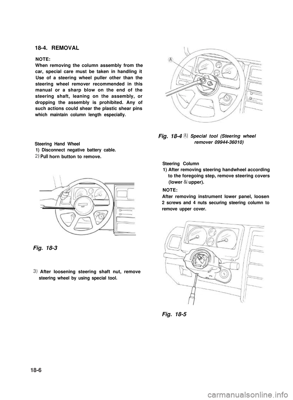
18-4. REMOVAL
NOTE:
When removing the column assembly from the
car, special care must be taken in handling it
Use of a steering wheel puller other than the
steering wheel remover recommended in this
manual or a sharp blow on the end of the
steering shaft, leaning on the assembly, or
dropping the assembly is prohibited. Any of
such actions could shear the plastic shear pins
which maintain column length especially.
Steering Hand Wheel
1) Disconnect negative battery cable.
2) Pull horn button to remove.
Fig. 18-3
3) After loosening steering shaft nut, remove
steering wheel by using special tool.
Fig. 18-4 @ Special tool (Steering wheel
remover 09944-36010)
Steering Column
1) After removing steering handwheel according
to the foregoing step, remove steering covers
(lower & upper).
NOTE:
After removing instrument lower panel, loosen
2 screws and 4 nuts securing steering column to
remove upper cover.
Fig. 18-5
18-6
Page 374 of 962
18-6. CHECKING STEERING COLUMN
FOR ACCIDENT DAMAGE
Cars involved in accidents resulting in body
damage or where the steering column has been
impacted may also have a damaged or misalign-
ed steering column.
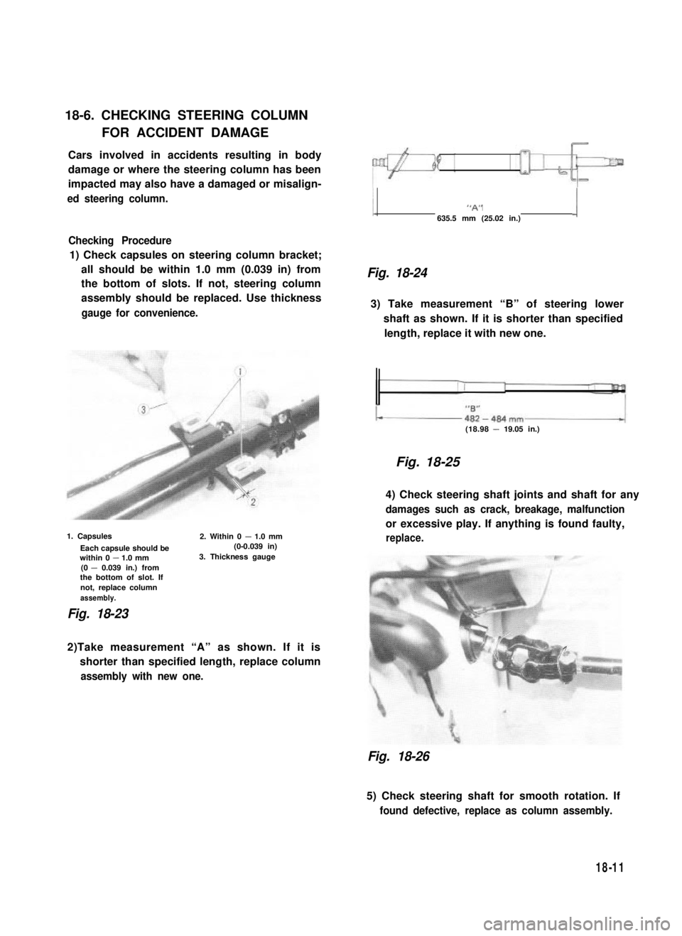
Checking Procedure
1) Check capsules on steering column bracket;
all should be within 1.0 mm (0.039 in) from
the bottom of slots. If not, steering column
assembly should be replaced. Use thickness
gauge for convenience.
1. Capsules
Each capsule should bewithin 0 - 1.0 mm(0 - 0.039 in.) fromthe bottom of slot. Ifnot, replace columnassembly.
2. Within 0 - 1.0 mm (0-0.039 in)3. Thickness gauge
Fig. 18-23
1 “A” j
635.5 mm (25.02 in.)
Fig. 18-24
3) Take measurement “B” of steering lower
shaft as shown. If it is shorter than specified
length, replace it with new one.
(18.98 - 19.05 in.)
Fig. 18-25
4) Check steering shaft joints and shaft for any
damages such as crack, breakage, malfunction
or excessive play. If anything is found faulty,
replace.
2)Take measurement “A” as shown. If it is
shorter than specified length, replace column
assembly with new one.
Fig. 18-26
5) Check steering shaft for smooth rotation. If
found defective, replace as column assembly.
18-11
Page 380 of 962
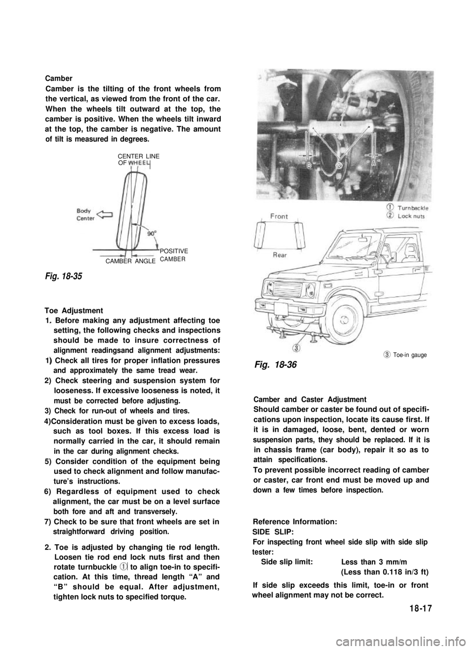
Camber
Camber is the tilting of the front wheels from
the vertical, as viewed from the front of the car.
When the wheels tilt outward at the top, the
camber is positive. When the wheels tilt inward
at the top, the camber is negative. The amount
of tilt is measured in degrees.
CENTER LINEOF yH,EEL
Fig. 18-35
CAMBER ANGLE
‘POSITIVE
CAMBER
Toe Adjustment
1. Before making any adjustment affecting toe
setting, the following checks and inspections
should be made to insure correctness of
alignment readingsand alignment adjustments:
1) Check all tires for proper inflation pressures
and approximately the same tread wear.
2) Check steering and suspension system for
looseness. If excessive looseness is noted, it
must be corrected before adjusting.
3) Check for run-out of wheels and tires.
4)Consideration must be given to excess loads,
such as tool boxes. If this excess load is
normally carried in the car, it should remain
in the car during alignment checks.
5) Consider condition of the equipment being
used to check alignment and follow manufac-
ture’s instructions.
6) Regardless of equipment used to check
alignment, the car must be on a level surface
both fore and aft and transversely.
7) Check to be sure that front wheels are set in
straightforward driving position.
2. Toe is adjusted by changing tie rod length.
Loosen tie rod end lock nuts first and then
rotate turnbuckle @ to align toe-in to specifi-
cation. At this time, thread length “A” and
“B” should be equal. After adjustment,
tighten lock nuts to specified torque.
@ Toe-in gauge
Fig. 18-36
Camber and Caster Adjustment
Should camber or caster be found out of specifi-
cations upon inspection, locate its cause first. If
it is in damaged, loose, bent, dented or worn
suspension parts, they should be replaced. If it is
in chassis frame (car body), repair it so as to
attain specifications.
To prevent possible incorrect reading of camber
or caster, car front end must be moved up and
down a few times before inspection.
Reference Information:
SIDE SLIP:
For inspecting front wheel side slip with side slip
tester:
Side slip limit:Less than 3 mm/m
(Less than 0.118 in/3 ft)
If side slip exceeds this limit, toe-in or front
wheel alignment may not be correct.
18-17
Page 418 of 962
INSPECTION
Inner Parts
NOTE:
After disassembly, soak all metal parts in ethyl
alcohol. Wipe rubber diaphragm and plastic parts
with a clean cloth. Use ethyl alcohol damped
cloth to wipe out heavy dirt Application of
much ethyl alcohol especially to rubber parts is
prohibited.
[ Rubber parts]
Wipe fluid from rubber parts and carefully
inspect each rubber part for cuts, nicks or other
damage. These parts are the key to the control
of air flow. If there is any question as to the
serviceability of rubber parts, REPLACE them.
[Metal parts]
BADLY DAMAGED ITEMS, OR THOSE
WHICH WOULD TAKE EXTENSIVE WORK
OR TIME TO REPAIR, SHOULD BE REPLAC-
ED. IN CASE OF DOUBT, INSTALL NEW
PARTS.
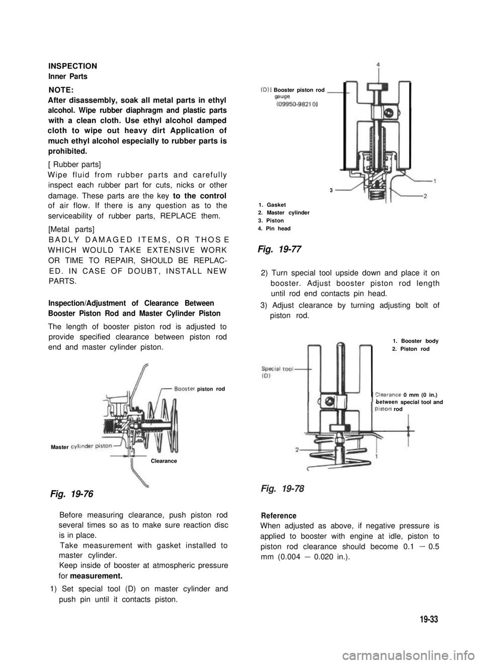
Inspection/Adjustment of Clearance Between
Booster Piston Rod and Master Cylinder Piston
The length of booster piston rod is adjusted to
provide specified clearance between piston rod
end and master cylinder piston.
Master
Fig. 19-76
Clearance
(D): Booster piston rod -mwe
(09950-98210)
3
1. Gasket2. Master cylinder
3. Piston
4. Pin head
Fig. 19-77
2) Turn special tool upside down and place it on
booster. Adjust booster piston rod length
until rod end contacts pin head.
3) Adjust clearance by turning adjusting bolt of
piston rod.
pistonrod
Before measuring clearance, push piston rod
several times so as to make sure reaction disc
is in place.
Take measurement with gasket installed to
master cylinder.
Keep inside of booster at atmospheric pressure
for measurement.
1) Set special tool (D) on master cylinder and
push pin until it contacts piston.
1. Booster body
2. Piston rod
%arance 0 mm (0 in.)betweenspecial tool andiston rod
Reference
When adjusted as above, if negative pressure is
applied to booster with engine at idle, piston to
piston rod clearance should become 0.1 - 0.5
mm (0.004 - 0.020 in.).
19-33
Fig. 19-78
Page 422 of 962
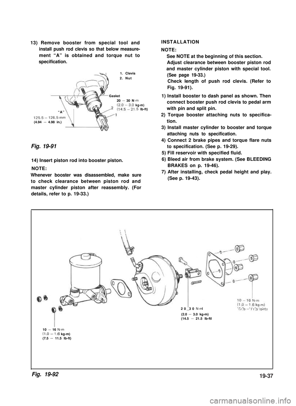
13) Remove booster from special tool and
install push rod clevis so that below measure-
ment “A” is obtained and torque nut to
specification.
-41. Clevis
2. Nut
Gasket20 - 30 N
“A”
125.5- 126.5mm(4.94 - 4.98 in.)\
.rnkg-m).5 lb-ft)
Fig. 19-91
14) Insert piston rod into booster piston.
NOTE:
Whenever booster was disassembled, make sure
to check clearance between piston rod and
INSTALLATION
NOTE:
See NOTE at the beginning of this section.
Adjust clearance between booster piston rod
and master cylinder piston with special tool.
(See page 19-33.)
Check length of push rod clevis. (Refer to
Fig. 19-91).
1) Install booster to dash panel as shown. Then
connect booster push rod clevis to pedal arm
with pin and split pin.
2) Torque booster attaching nuts to specifica-
tion.
3) Install master cylinder to booster and torque
attaching nuts to specification.
4) Connect 2 brake pipes and torque flare nuts
to specification. (See p. 19-29).
5) Fill reservoir with specified fluid.
6) Bleed air from brake system. (See BLEEDING
BRAKES on p. 19-46).
7) After installing, check pedal height and play.
(See p. 19-43).
master cylinder piston after reassembly. (For
details, refer to p. 19-33.)
20 30 N.m-(2.0 - 3.0 kg-m)(14.5 - 21.5 lb-ftl
10 - 16 N.m(1.0-1.6 kg-m)(7.5 - 11.5 lb-ft)
Fig. 19-9219-37
Page 428 of 962
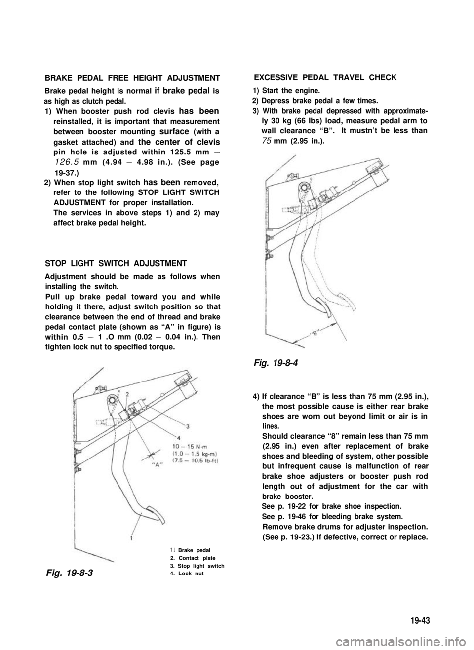
BRAKE PEDAL FREE HEIGHT ADJUSTMENT
Brake pedal height is normal if brake pedal is
as high as clutch pedal.
1) When booster push rod clevis has been
reinstalled, it is important that measurement
between booster mounting surface (with a
gasket attached) and the center of clevis
pin hole is adjusted within 125.5 mm -
126.5 mm (4.94 - 4.98 in.). (See page
19-37.)
2) When stop light switch has been removed,
refer to the following STOP LIGHT SWITCH
ADJUSTMENT for proper installation.
The services in above steps 1) and 2) may
affect brake pedal height.
STOP LIGHT SWITCH ADJUSTMENT
Adjustment should be made as follows when
installing the switch.
Pull up brake pedal toward you and while
holding it there, adjust switch position so that
clearance between the end of thread and brake
pedal contact plate (shown as “A” in figure) is
within 0.5 -1 .O mm (0.02 - 0.04 in.). Then
tighten lock nut to specified torque.
1. Brake pedal
2. Contact plate
3. Stop light switch4. Lock nut
EXCESSIVE PEDAL TRAVEL CHECK
1) Start the engine.
2) Depress brake pedal a few times.
3) With brake pedal depressed with approximate-
ly 30 kg (66 Ibs) load, measure pedal arm to
wall clearance “B”.It mustn’t be less than
75 mm (2.95 in.).
Fig. 19-8-4
4) If clearance “B” is less than 75 mm (2.95 in.),
the most possible cause is either rear brake
shoes are worn out beyond limit or air is in
lines.
Should clearance “8” remain less than 75 mm
(2.95 in.) even after replacement of brake
shoes and bleeding of system, other possible
but infrequent cause is malfunction of rear
brake shoe adjusters or booster push rod
length out of adjustment for the car with
brake booster.
See p. 19-22 for brake shoe inspection.
See p. 19-46 for bleeding brake system.
Remove brake drums for adjuster inspection.
(See p. 19-23.) If defective, correct or replace.
Fig. 19-8-3
19-43
Page 473 of 962
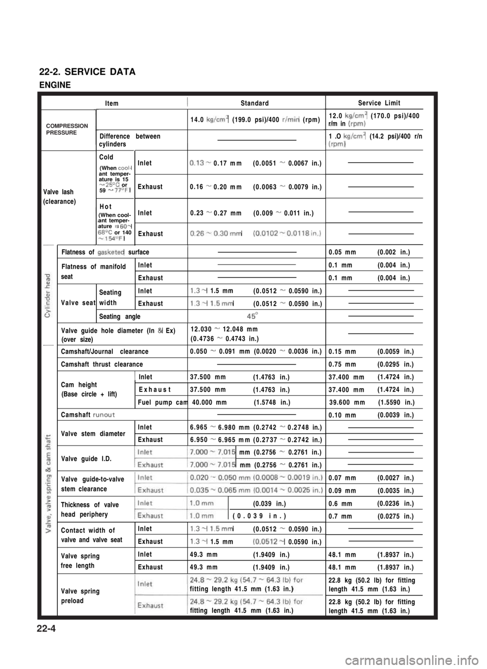
22-2. SERVICE DATA
ENGINE
ItemStandardService Limit
12.0 kg/cm2 (170.0 psi)/400r/m in (rpm)
1 .O kg/cm2 (14.2 psi)/400 r/n
(m-d
14.0 kg/cm2 (199.0 psi)/400 r/min (rpm)
Difference betweencylinders
Cold
(When cooi-ant temper-ature is 15- 25T or59 - 77OF)
Hot
(When cool-ant temper-ature IS 60-68T or 140-154OFJ
Valve lash
(clearance)
Inlet
Exhaust
Inlet
Exhaust
0.13-0.17mm(0.0051 - 0.0067 in.)
0.16 -0.20mm(0.0063 - 0.0079 in.)
0.23 -0.27mm(0.009 - 0.011 in.)
0.26%0.30mm (0.0102-0.0118in.)
/0.05 mm(0.002 in.)Flatness of gasketed surface
Flatness of manifoldInlet
seatExhaust
SeatingInlet
Valve seat widthExhaust
Seating angle
1.3- 1.5 mm(0.0512 - 0.0590 in.)
1.3- 1.5mm(0.0512 - 0.0590 in.)
45O
0.1 mm(0.004 in.)
0.1 mm(0.004 in.)
Valve guide hole diameter (In & Ex)12.030 - 12.048 mm
(over size)(0.4736 - 0.4743 in.)
Camshaft/Journal clearance0.050 - 0.091 mm (0.0020 - 0.0036 in.)0.15 mm(0.0059 in.)
0.75 mm(0.0295 in.)Camshaft thrust clearance
1 Inlet37.500 mm(1.4763 in.)37.400 mm(1.4724 in.)Cam heightI
(Base circle + lift) Exhaust37.500 mm(1.4763 in.)
Fuel pump cam 40.000 mm(1.5748 in.)
37.400 mm(1.4724 in.)
39.600 mm(1.5590 in.)
Camshaft runout0.10 mm(0.0039 in.)
Inlet6.965-6.980mm(0.2742-0.2748in.)Valve stem diameterExhaust6.950-6.965mm(0.2737-0.2742in.)
Valve guide I.D.7.000 - 7.015 mm (0.2756 - 0.2761 in.)
w.015 mm (0.2756 - 0.2761 in.)
Valve guide-to-valve
stem clearance
0.07 mm(0.0027 in.)
0.09 mm(0.0035 in.)
Thickness of valve(0.039 in.)
head peripherymw (0.039 in.)
0.6 mm(0.0236 in.)
0.7 mm(0.0275 in.)
Contact width ofInlet1.3- 1.5mm(0.0512 - 0.0590 in.)
valve and valve seatExhaust1.3- 1.5 mm(0.0512- 0.0590 in.)
48.1 mm(1.8937 in.)Valve spring
free length
Inlet
Exhaust
49.3 mm(1.9409 in.)
49.3 mm(1.9409 in.)48.1 mm(1.8937 in.)
Valve spring
preload
fitting length 41.5 mm (1.63 in.)
fitting length 41.5 mm (1.63 in.)
22.8 kg (50.2 lb) for fitting
length 41.5 mm (1.63 in.)
22.8 kg (50.2 lb) for fitting
length 41.5 mm (1.63 in.)
COMPRESSIONPRESSURE
22-4