1987 SUZUKI GRAND VITARA alternator
[x] Cancel search: alternatorPage 21 of 962
![SUZUKI GRAND VITARA 1987 Service Repair Manual 1-2. ENGINE AND EMISSION CONTROL
1. WATER PUMP BELT INSPECTION
AND REPLACEMENT
[INSPECTION]
1) Disconnect negative battery lead at battery.
2) Inspect belt for cracks, cuts, deformation,
wear and clea SUZUKI GRAND VITARA 1987 Service Repair Manual 1-2. ENGINE AND EMISSION CONTROL
1. WATER PUMP BELT INSPECTION
AND REPLACEMENT
[INSPECTION]
1) Disconnect negative battery lead at battery.
2) Inspect belt for cracks, cuts, deformation,
wear and clea](/manual-img/20/57437/w960_57437-20.png)
1-2. ENGINE AND EMISSION CONTROL
1. WATER PUMP BELT INSPECTION
AND REPLACEMENT
[INSPECTION]
1) Disconnect negative battery lead at battery.
2) Inspect belt for cracks, cuts, deformation,
wear and cleanliness. If any defect, replace.
Check belt for tension. The belt is in’ proper
tension if it deflects 6 to 9 mm (0.24 - 0.35
in.) under thumb pressure (about 10 kg or
22 lb.)..
Belt tension6 - 9 mm (0.24 - 0.35 in.)
specificationas deflection
pulley
3) If the belt is too tight or too loose, adjust it
to specification by adjusting alternator
position.
4) Tighten alternator adjusting bolt and pivot
bolts.
5) Connect negative battery lead to battery.
[REPLACEMENT]
1) Disconnect negative battery lead at battery.
2) Loosen alternator adjusting bolt and pivot
bolts.
3) Replace water pump belt.
4) Adjust belt tension to specification and
tighten alternator adjusting bolt and pivot
bolts.
5) Connect negative battery lead to battery.
2. CAMSHAFT TIMING BELT INSPECTION
1) Disconnect negative battery lead at battery.
2) Loosen fan drive belt, and remove 4 bolts
securing radiator shroud panel and 4 nuts
securing engine cooling fan & clutch. Then
remove radiator shroud and cooling fan &
clutch at the same time.
3) Remove water pump belt and pump pulley.
4) Remove crankshaft pulley by removing 4
pulley bolts. The crankshaft timing belt
pulley bolt at the center need not be loosen-
ed.2 1
‘31. Key
2. Crankshaft pulley
3. Pulley bolt
1-5
Page 39 of 962
2-1.
2-2.
2-3.
2-4.
2-5.
2-6.
2-7.
2-6.
2-9.
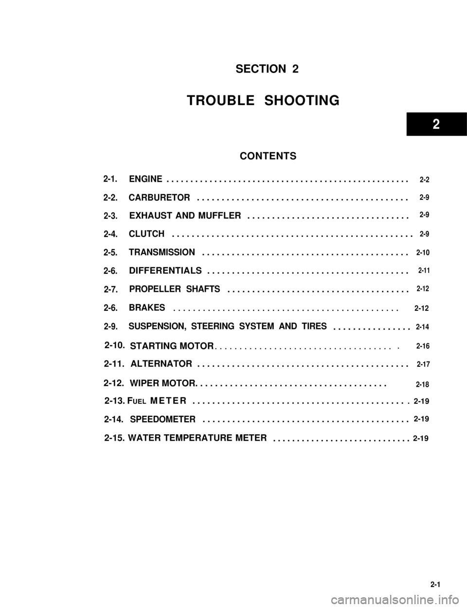
SECTION 2
TROUBLE SHOOTING
CONTENTS
ENGINE...................................................2-2
CARBURETOR...........................................
EXHAUST AND MUFFLER.................................
CLUTCH.................................................2-9
TRANSMISSION..........................................
DIFFERENTIALS.........................................2-11
PROPELLER SHAFTS.....................................2-12
BRAKES.............................................. 2-12
SUSPENSION, STEERING SYSTEM AND TIRES................
STARTING MOTOR.....................................
2-11. ALTERNATOR...........................................
FUEL METER............................................ 2-19
2-14. SPEEDOMETER..........................................2-19
2-15. WATER TEMPERATURE METER.............................2-19
2-9
2-9
2-10
2-14
2-16
2-17
2-18WIPER MOTOR.......................................
2-10.
2-12.
2-13.
2-1
2
Page 55 of 962
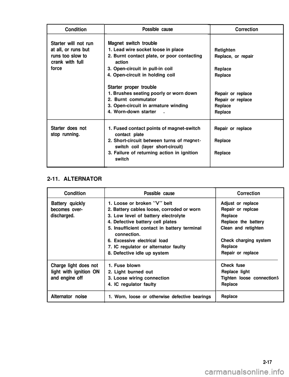
Condition
Starter will not run
at all, or runs but
runs too slow to
crank with full
force
Starter does not
stop running.
2-11. ALTERNATOR
Condition
Battery quickly
becomes over-
discharged.
Charge light does not
light with ignition ON
and engine off
Alternator noise
Possible cause
Magnet switch trouble
1. Lead wire socket loose in place
2. Burnt contact plate, or poor contacting
action
3. Open-circuit in pull-in coil
4. Open-circuit in holding coil
Starter proper trouble
1. Brushes seating poorly or worn down
2. Burnt commutator
3. Open-circuit in armature winding
4. Worn-down starter.
1. Fused contact points of magnet-switch
contact plate
2. Short-circuit between turns of magnet-
switch coil (layer short-circuit)
3. Failure of returning action in ignition
switch
Possible cause
1. Loose or broken “V” belt
2. Battery cables loose, corroded or worn
3. Low level of battery electrolyte
4. Defective battery cell plates
5. Insufficient contact in battery terminal
connection.
6. Excessive electrical load
7. IC regulator or alternator faulty
8. Defective idle up system
1. Fuse blown
2. Light burned out
3. Loose wiring connection
4. IC regulator faulty
1. Worn, loose or otherwise defective bearings
Correction
Retighten
Replace, or repair
Replace
Replace
Repair or replace
Repair or replace
Replace
Replace
Repair or replace
Replace
Replace
Correction
Adjust or replace
Repair or replcae
Replace
Replace the battery
Clean and retighten
Check charging system
Replace
Repair or replace
Check fuse
Replace light
Tighten loose connection!
Replace
i
Replace
2-17
Page 62 of 962
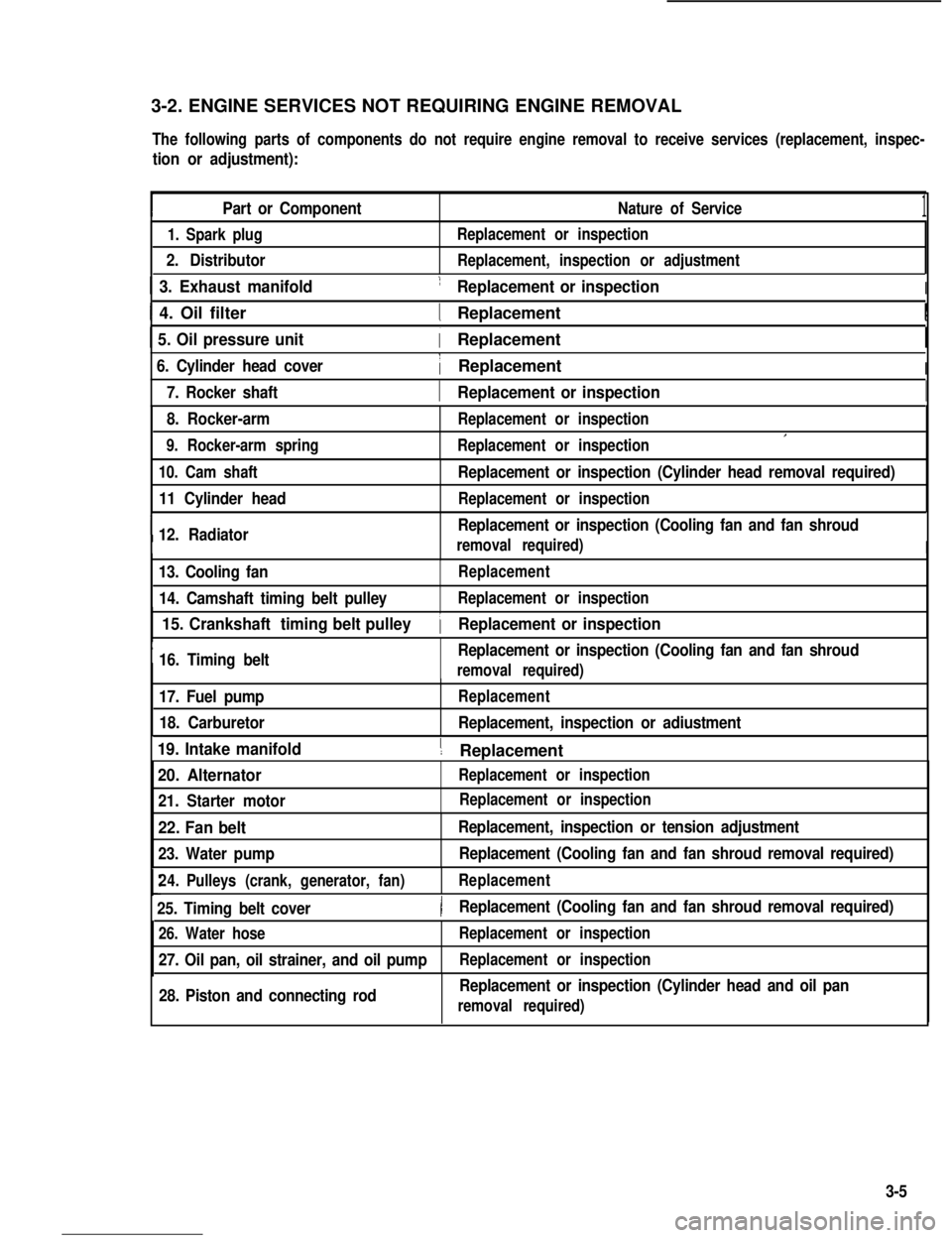
3-2. ENGINE SERVICES NOT REQUIRING ENGINE REMOVAL
The following parts of components do not require engine removal to receive services (replacement, inspec-
tion or adjustment):
Part or ComponentNature of Service1
1. Spark plug
2. Distributor
Replacement or inspection
Replacement, inspection or adjustment
1 3. Exhaust manifold1 Replacement or inspectionI
I 4. Oil filter1 ReplacementI
1 5. Oil pressure unit( Replacement
6. Cylinder head cover1 ReplacementI
I7. Rocker shaft1 Replacement or inspectionI
8. Rocker-arm
9. Rocker-arm spring
Replacement or inspection
Replacement or inspectionI
10. Cam shaft
11 Cylinder head
I12. Radiator
Replacement or inspection (Cylinder head removal required)
Replacement or inspection
Replacement or inspection (Cooling fan and fan shroud
removal required)I
13. Cooling fan
14. Camshaft timing belt pulley
Replacement
Replacement or inspection
I
15. Crankshaft timing belt pulley
16. Timing beltReplacement or inspection (Cooling fan and fan shroud
1 Replacement or inspection
removal required)
17. Fuel pump
18. Carburetor
Replacement
Replacement, inspection or adiustment
19. Intake manifold1 ReplacementI
20. Alternator
21. Starter motor
Replacement or inspection
22. Fan belt
23. Water pump
Replacement, inspection or tension adjustment
Replacement (Cooling fan and fan shroud removal required)
24.Pulleys (crank, generator, fan)Replacement
25. Timing belt cover)Replacement (Cooling fan and fan shroud removal required)
26. Water hose
27. Oil pan, oil strainer, and oil pump
Replacement or inspection
Replacement or inspection
28. Piston and connecting rodReplacement or inspection (Cylinder head and oil pan
removal required)
Replacement or inspection
3-5
Page 63 of 962
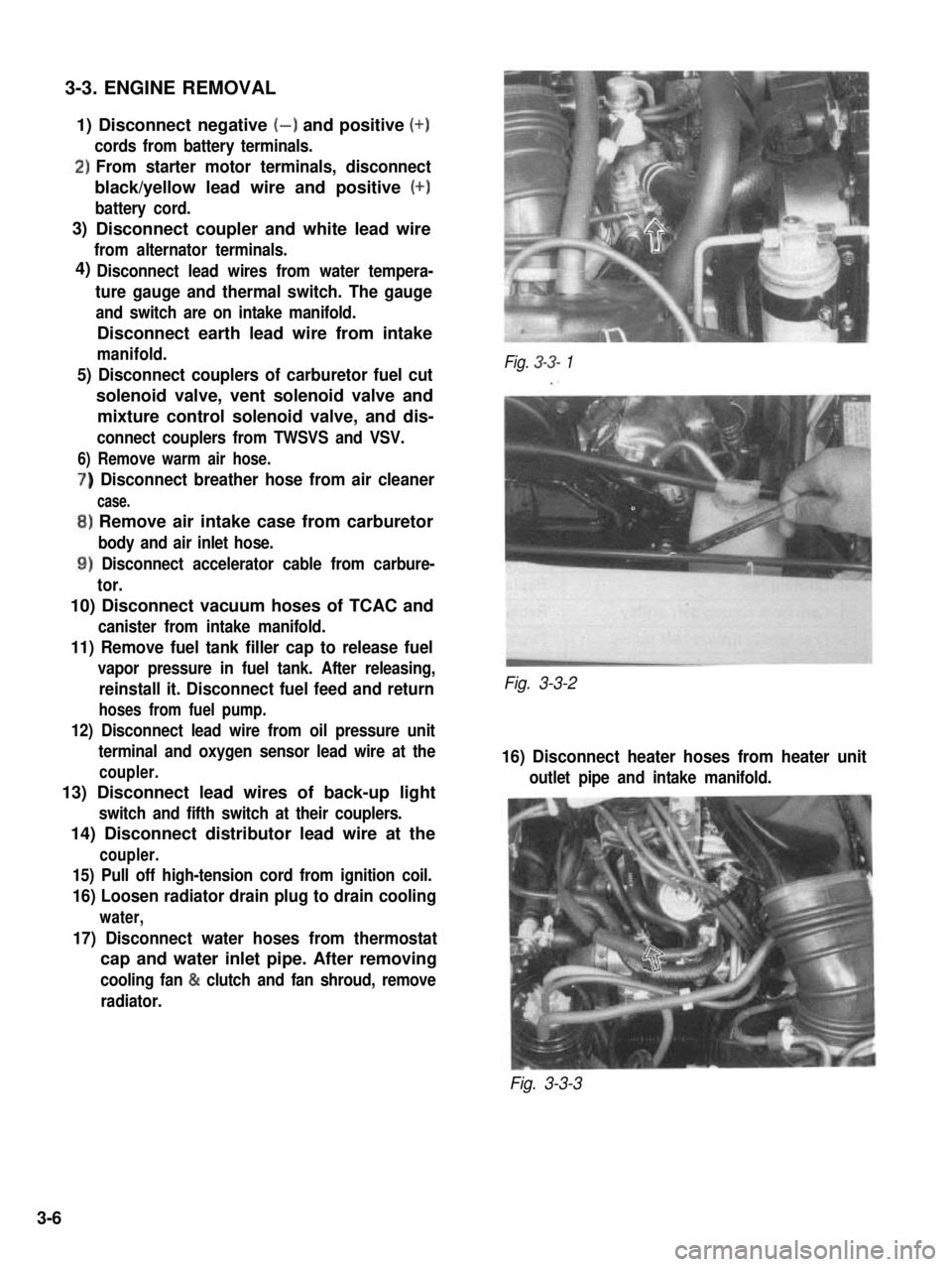
3-3. ENGINE REMOVAL
1) Disconnect negative (-) and positive (+)
cords from battery terminals.
‘)From starter motor terminals, disconnect
black/yellow lead wire and positive (+)
battery cord.
Disconnect coupler and white lead wire
from alternator terminals.
Disconnect lead wires from water tempera-
ture gauge and thermal switch. The gauge
and switch are on intake manifold.
Disconnect earth lead wire from intake
manifold.
5) Disconnect couplers of carburetor fuel cut
solenoid valve, vent solenoid valve and
mixture control solenoid valve, and dis-
connect couplers from TWSVS and VSV.
6) Remove warm air hose.
) Disconnect breather hose from air cleaner
case.
,) Remove air intake case from carburetor
body and air inlet hose.
1) Disconnect accelerator cable from carbure-
tor.
10) Disconnect vacuum hoses of TCAC and
canister from intake manifold.
11) Remove fuel tank filler cap to release fuel
vapor pressure in fuel tank. After releasing,
reinstall it. Disconnect fuel feed and return
hoses from fuel pump.
12) Disconnect lead wire from oil pressure unit
terminal and oxygen sensor lead wire at the
coupler.
13) Disconnect lead wires of back-up light
switch and fifth switch at their couplers.
14) Disconnect distributor lead wire at the
coupler.
15) Pull off high-tension cord from ignition coil.
16) Loosen radiator drain plug to drain cooling
water,
17) Disconnect water hoses from thermostat
cap and water inlet pipe. After removing
cooling fan & clutch and fan shroud, remove
radiator.
Fig. 3-3- 1
Fig. 3-3-2
16) Disconnect heater hoses from heater unit
outlet pipe and intake manifold.
Fig. 3-3-3
3)
4)
3-6
Page 67 of 962
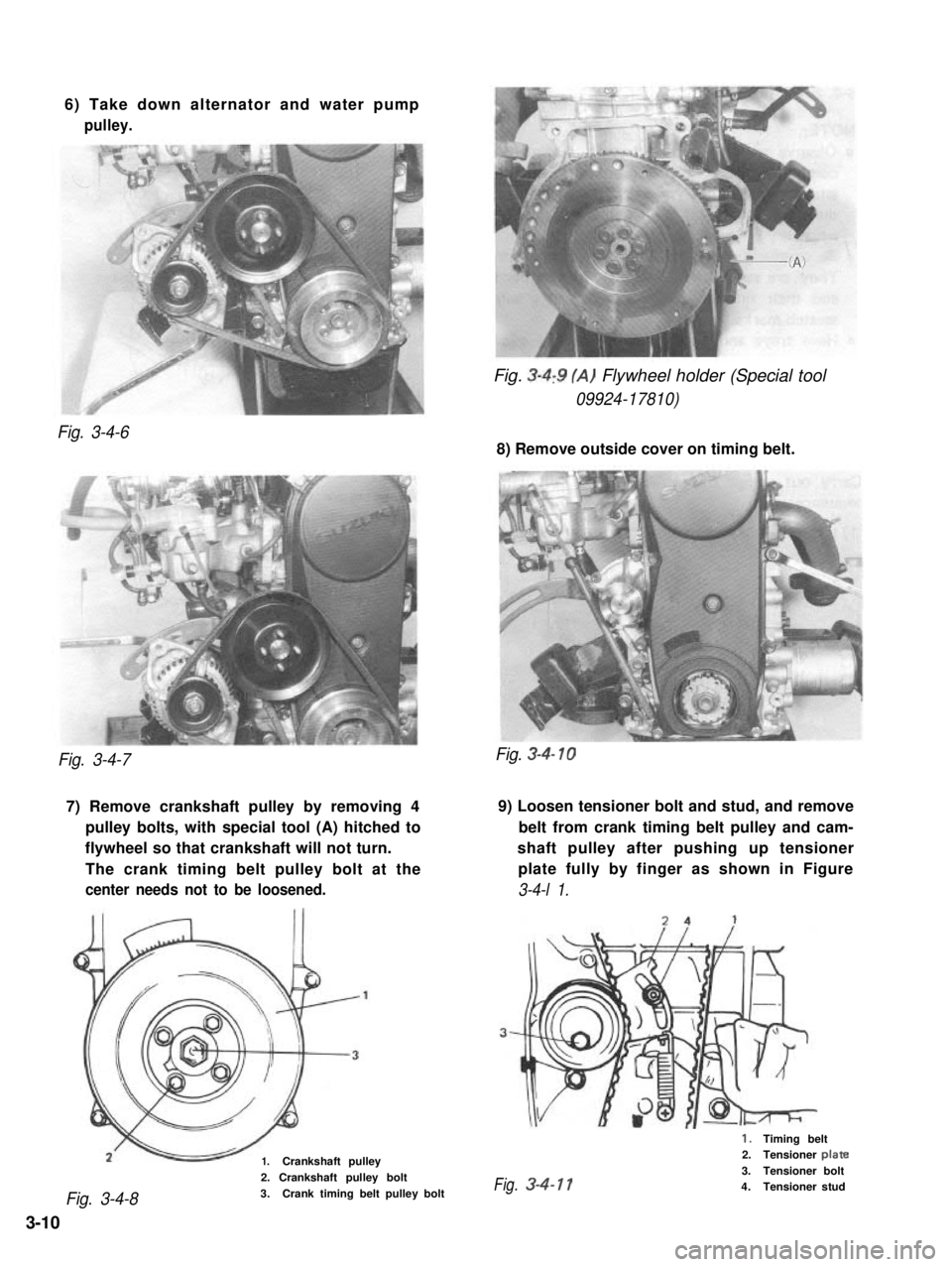
6) Take down alternator and water pump
pulley.
Fig. 3-4,9 (A) Flywheel holder (Special tool
09924-17810)
Fig. 3-4-6
8) Remove outside cover on timing belt.
Fig. 3-4-7
7) Remove crankshaft pulley by removing 49) Loosen tensioner bolt and stud, and remove
pulley bolts, with special tool (A) hitched tobelt from crank timing belt pulley and cam-
flywheel so that crankshaft will not turn.shaft pulley after pushing up tensioner
The crank timing belt pulley bolt at theplate fully by finger as shown in Figure
center needs not to be loosened.3-4-l 1.
1.Crankshaft pulley
Fig. 3-4-8
2. Crankshaft pulley bolt
3.Crank timing belt pulley bolt
Fig. 3-4- 10
1.Timing belt2.Tensioner plate
3.Tensioner boltFig.3-4-114.Tensioner stud
3-10
Page 107 of 962
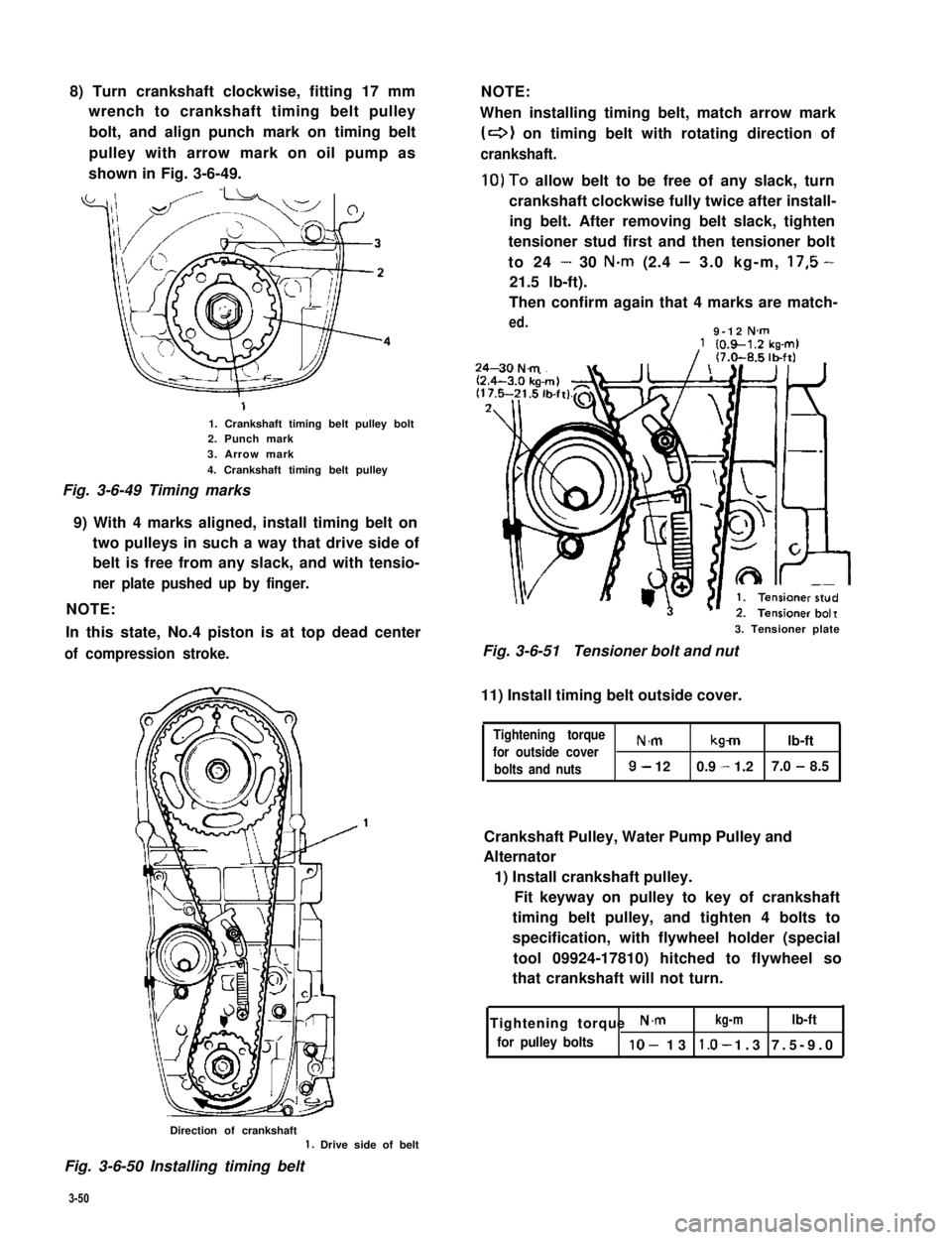
8) Turn crankshaft clockwise, fitting 17 mm
wrench to crankshaft timing belt pulley
bolt, and align punch mark on timing belt
pulley with arrow mark on oil pump as
shown in Fig. 3-6-49.
1. Crankshaft timing belt pulley bolt2. Punch mark3. Arrow mark
4. Crankshaft timing belt pulley
Fig. 3-6-49 Timing marks
9) With 4 marks aligned, install timing belt on
two pulleys in such a way that drive side of
belt is free from any slack, and with tensio-
ner plate pushed up by finger.
NOTE:
In this state, No.4 piston is at top dead center
of compression stroke.
NOTE:
When installing timing belt, match arrow mark
(+I on timing belt with rotating direction of
crankshaft.
10)To allow belt to be free of any slack, turn
crankshaft clockwise fully twice after install-
ing belt. After removing belt slack, tighten
tensioner stud first and then tensioner bolt
to 24 - 30 N.m (2.4 - 3.0 kg-m, 17,5 -
21.5 lb-ft).
Then confirm again that 4 marks are match-
ed.9-12 N-m
3. Tensioner plate
Fig. 3-6-51Tensioner bolt and nut
11) Install timing belt outside cover.
Tightening torque
for outside coverN.mkmlb-ft
bolts and nuts9- 120.9 - 1.27.0 - 8.5
Crankshaft Pulley, Water Pump Pulley and
Alternator
1) Install crankshaft pulley.
Fit keyway on pulley to key of crankshaft
timing belt pulley, and tighten 4 bolts to
specification, with flywheel holder (special
tool 09924-17810) hitched to flywheel so
that crankshaft will not turn.
Tightening torque N.mkg-mlb-ft
for pulley boltslo- 13 1.3 7.5-9.0*
Direction of crankshaft1. Drive side of belt
Fig. 3-6-50 Installing timing belt
3-50
Page 108 of 962
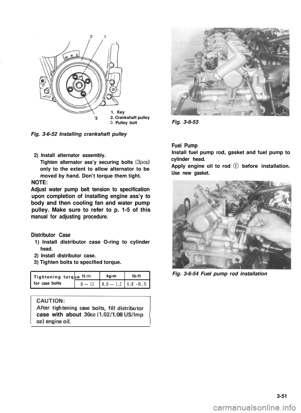
-1. Key
‘32. Crankshaft pulley3. Pulley bolt
Fig. 3-6-52 Installing crankshaft pulley
2) Install alternator assembly.
Tighten alternator ass’y securing bolts (3pcs)
only to the extent to allow alternator to be
moved by hand. Don’t torque them tight.
NOTE:
Adjust water pump belt tension to specification
upon completion of installing engine ass’y to
body and then cooling fan and water pump
pulley. Make sure to refer to p. 1-5 of this
manual for adjusting procedure.
Distributor Case
1) Install distributor case O-ring to cylinder
head.
2) Install distributor case.
3) Tighten bolts to specified torque.
Tightening torque N.mkg-mlb-ft
forcasebolts8-120.8-1.26.0-8.5
Fig. 3-6-53
Fuel Pump
Install fuel pump rod, gasket and fuel pump to
cylinder head.
Apply engine oil to rod @ before installation.
Use new gasket.
Fig. 3-6-54 Fuel pump rod installation
case with about 3Occ (1.02/1.05 US/Imp
3-51