1987 SUZUKI GRAND VITARA ad blue
[x] Cancel search: ad bluePage 31 of 962
1) Replace fuel hoses (pipe to fuel pump, pipe to
fuel filter and breather hose) in fuel feed and
return lines with new ones.
2) Remove fuel tank.
3) Replace return hose (tank to return pipe)
with new one.
4) Clamp hoses securely.
5) Install fuel tank referring to p. 4-35.
6) After installation, start engine and check it
for leaks.
27. IDLE SPEED INSPECTION
NOTE:
Before starting engine, place transmission gear
shift lever in “Neutral”, and set parking brake
and block drive wheels.
1) Warm up engine to normal operating tempe-
rature.
2) Check to ensure that idle speed is within
750 - 850 r/min (rpm).
3) If idle speed is not within specified range,
adjust idle speed. Refer to MAINTENANCE
SERVICE (p. 4-26) for procedures to check
and adjust idle speed.
28. IDLE MIXTURE INSPECTION
1) Warm up engine to normal operating tem-
perature.
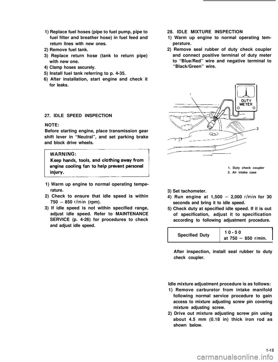
2) Remove seal rubber of duty check coupler
and connect positive terminal of duty meter
to “Blue/Red” wire and negative terminal to
“Black/Green” wire.
1
1. Duty check coupler
2. Air intake case
3) Set tachometer.
4) Run engine at 1,500 - 2,000 r/min for 30
seconds and bring it to idle speed.
5) Check duty at specified idle speed. If it is out
of specification,adjust it to specification
according to following adjustment procedure.
Specified Duty10-50
at 750 - 850 r/min.I
After inspection, install seal rubber to duty
check coupler.
Idle mixture adjustment procedure is as follows:
1) Remove carburetor from intake manifold
following normal service procedure to gain
access to mixture adjusting screw pin covering
mixture adjusting screw.
2) Drive out mixture adjusting screw pin using
about 4.5 mm (0.18 in) thick iron rod as
shown below.
1-15
Page 32 of 962
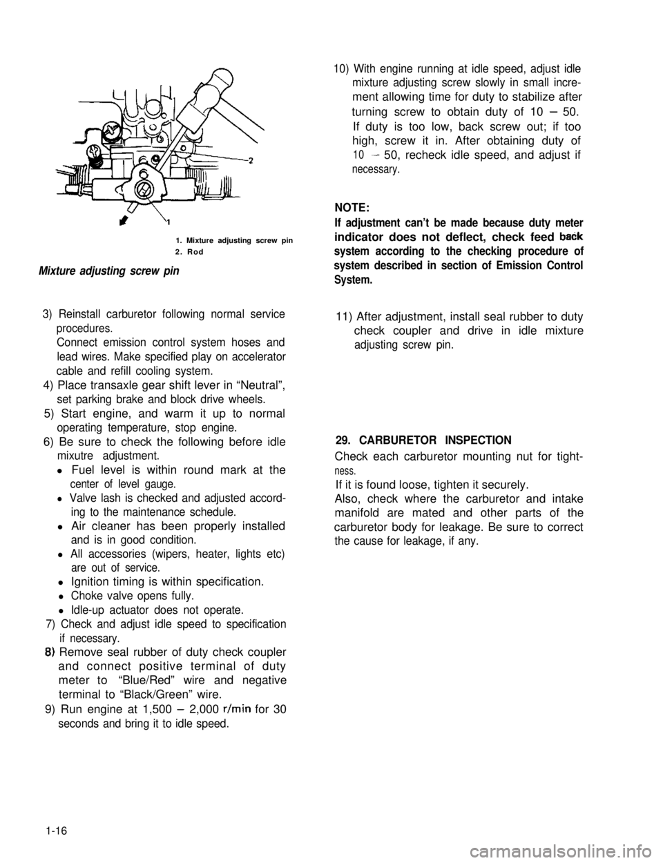
1. Mixture adjusting screw pin
2. Rod
Mixture adjusting screw pin
10) With engine running at idle speed, adjust idle
mixture adjusting screw slowly in small incre-
ment allowing time for duty to stabilize after
turning screw to obtain duty of 10 - 50.
If duty is too low, back screw out; if too
high, screw it in. After obtaining duty of
10- 50, recheck idle speed, and adjust if
necessary.
NOTE:
If adjustment can’t be made because duty meter
indicator does not deflect, check feed baCk
system according to the checking procedure of
system described in section of Emission Control
System.
3) Reinstall carburetor following normal service
procedures.
Connect emission control system hoses and
lead wires. Make specified play on accelerator
cable and refill cooling system.
11) After adjustment, install seal rubber to duty
check coupler and drive in idle mixture
adjusting screw pin.
4) Place transaxle gear shift lever in “Neutral”,
set parking brake and block drive wheels.
5) Start engine, and warm it up to normal
operating temperature, stop engine.
6) Be sure to check the following before idle
mixutre adjustment.
l Fuel level is within round mark at the
center of level gauge.
l Valve lash is checked and adjusted accord-
ing to the maintenance schedule.
l Air cleaner has been properly installed
and is in good condition.
l All accessories (wipers, heater, lights etc)
are out of service.
29. CARBURETOR INSPECTION
Check each carburetor mounting nut for tight-
ness.
If it is found loose, tighten it securely.
Also, check where the carburetor and intake
manifold are mated and other parts of the
carburetor body for leakage. Be sure to correct
the cause for leakage, if any.
l Ignition timing is within specification.
l Choke valve opens fully.
l Idle-up actuator does not operate.
7) Check and adjust idle speed to specification
if necessary.
8) Remove seal rubber of duty check coupler
and connect positive terminal of duty
meter to“Blue/Red” wire and negative
terminal to “Black/Green” wire.
9) Run engine at 1,500 - 2,000 r/min for 30
seconds and bring it to idle speed.
1-16
Page 89 of 962
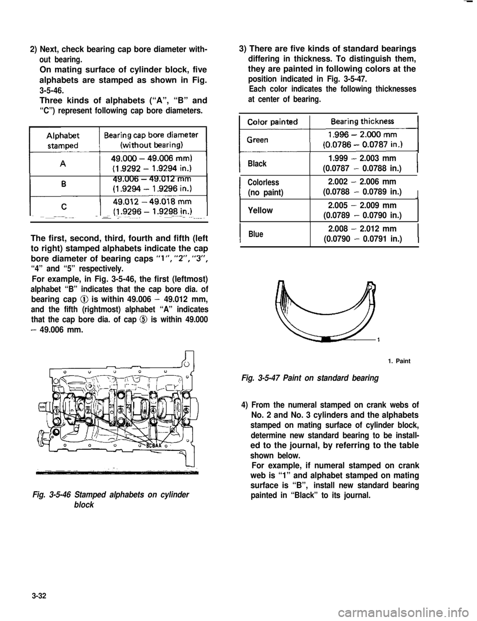
2) Next, check bearing cap bore diameter with-
out bearing.
On mating surface of cylinder block, five
alphabets are stamped as shown in Fig.
3-5-46.
Three kinds of alphabets (“A”, “B” and
“C”) represent following cap bore diameters.
The first, second, third, fourth and fifth (left
to right) stamped alphabets indicate the cap
bore diameter of bearing caps “l”, “2”, “3”,
“4” and “5” respectively.
For example, in Fig. 3-5-46, the first (leftmost)
alphabet “B” indicates that the cap bore dia. of
bearing cap @ is within 49.006 - 49.012 mm,
and the fifth (rightmost) alphabet “A” indicates
that the cap bore dia. of cap @ is within 49.000
- 49.006 mm.
Fig. 3-5-46 Stamped alphabets on cylinder
block
3) There are five kinds of standard bearings
differing in thickness. To distinguish them,
they are painted in following colors at the
position indicated in Fig. 3-5-47.
Each color indicates the following thicknesses
at center of bearing.
IBlack1.999 - 2.003 mm
(0.0787 - 0.0788 in.)I
I
Colorless2.002 - 2.006 mm
(no paint)(0.0788 - 0.0789 in.)I9
Yellow2.005 - 2.009 mm
(0.0789 - 0.0790 in.)
IBlue2.008 - 2.012 mm
(0.0790 - 0.0791 in.)I
1. Paint
Fig. 3-5-47 Paint on standard bearing
4) From the numeral stamped on crank webs of
No. 2 and No. 3 cylinders and the alphabets
stamped on mating surface of cylinder block,
determine new standard bearing to be install-
ed to the journal, by referring to the table
shown below.
For example, if numeral stamped on crank
web is “1” and alphabet stamped on mating
surface is “B”,install new standard bearing
painted in “Black” to its journal.
3-32
Page 90 of 962
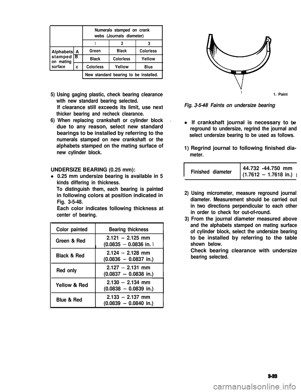
Numerals stamped on crank
webs (Journals diameter)
123
Alphabets AGreenBlackColorless
stamped Bon matingBlackColorlessYellow
surfacecColorlessYellowBlue
New standard bearing to be installed.
5) Using gaging plastic, check bearing clearance
with new standard bearing selected.
If clearance still exceeds its limit, use next
thicker bearing and recheck clearance.
6) When replacing crankshaft or cylinder block.
due to any reason, select new standard
bearings to be installed by referring to the
numerals stamped on new crankshaft or the
alphabets stamped on the mating surface of
new cylinder block.
UNDERSIZE BEARING (0.25 mm):
l 0.25 mm undersize bearing is available in 5
kinds differing in thickness.
To distinguish them, each bearing is painted
in following colors at position indicated in
Fig. 3-5-48.
Each color indicates following thickness at
center of bearing.
Color paintedBearing thicknessI
Green & Red2.121 - 2.125 mm
(0.0835 - 0.0836 in. )III
Black & Red2.124 - 2.128 mm
(0.0836 - 0.0837 in.)
Red only2.127 - 2.131 mm
(0.0837 - 0.0838 in.)I
Yellow & Red2.130 - 2.134 mm
(0.0838 - 0.0839 in.)
Blue & Red2.133 - 2.137 mm
(0.0839 - 0.0840 in.)I
11. Paint
Fig. 3-5-48 Faints on undersize bearing
l If crankshaft journal is necessary to be
reground to undersize, regrind the journal and
select undersize bearing to be used as follows.
1) Regrind journal to following finished dia-
meter.
IFinished diameter44.732 -44.750 mm
(1.7612 - 1.7618 in.)I
2) Using micrometer, measure reground journal
diameter. Measurement should be carried out
in two directions perpendicular to each other
in order to check for out-of-round.
3) From the journal diameter measured above
and the alphabets stamped on mating surface
of cylinder block, select the undersize bearing
to be installed by referring to the table
shown below.
Check bearing clearance with undersize
bearing selected.
3-33
Page 91 of 962
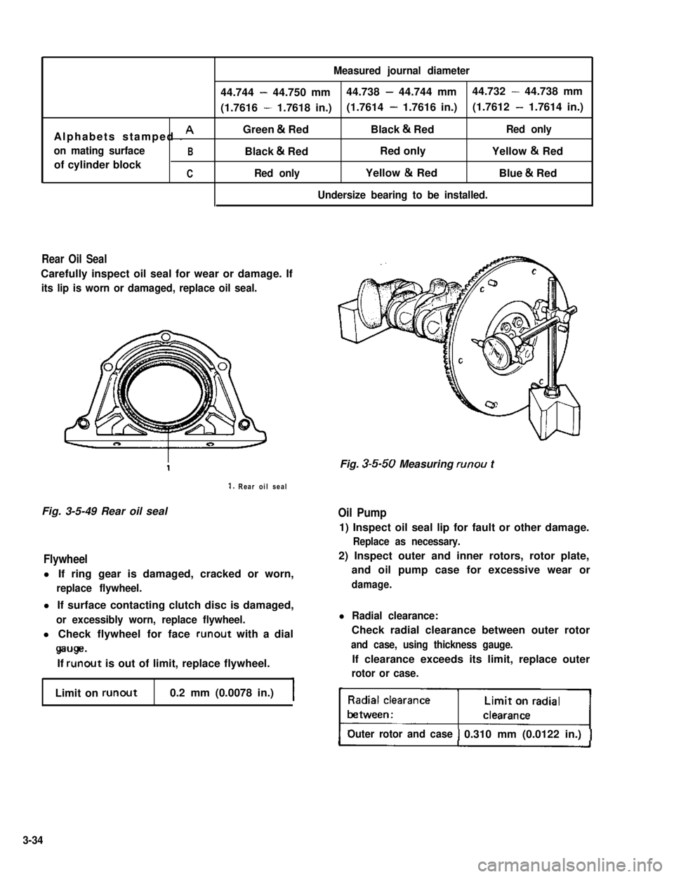
Measured journal diameter
44.744 - 44.750 mm44.738 - 44.744 mm44.732 - 44.738 mm
(1.7616 - 1.7618 in.)(1.7614 - 1.7616 in.)(1.7612 - 1.7614 in.)
Alphabets stamped I AGreen & RedBlack & RedRed only
on mating surfaceBBlack & RedRed onlyYellow & Red
of cylinder blockCRed onlyYellow & RedBlue & Red
Undersize bearing to be installed.
Rear Oil Seal
Carefully inspect oil seal for wear or damage. If
its lip is worn or damaged, replace oil seal.
1. Rear oil seal
Fig. 3-5-49 Rear oil sealOil Pump
Flywheel
l If ring gear is damaged, cracked or worn,
replace flywheel.
l If surface contacting clutch disc is damaged,
or excessibly worn, replace flywheel.
l Check flywheel for face runout with a dial
wge.
If runout is out of limit, replace flywheel.
Limit on runout0.2 mm (0.0078 in.)
Fig. 3-5-50 Measuring runou t
1) Inspect oil seal lip for fault or other damage.
Replace as necessary.
2) Inspect outer and inner rotors, rotor plate,
and oil pump case for excessive wear or
damage.
l Radial clearance:
Check radial clearance between outer rotor
and case, using thickness gauge.
If clearance exceeds its limit, replace outer
rotor or case.
Outer rotor and case0.310 mm (0.0122 in.)
3-34
Page 142 of 962
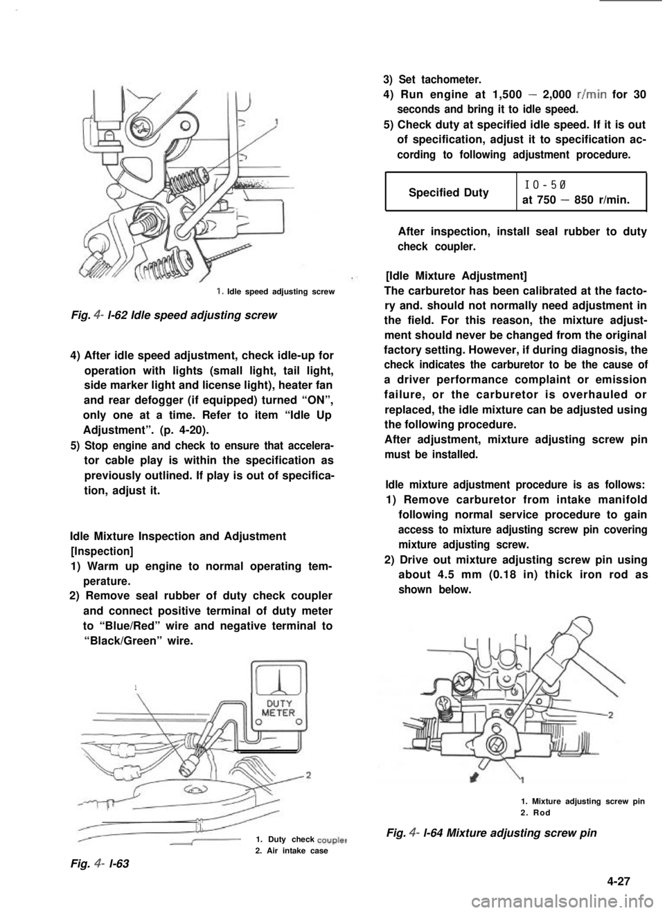
1. Idle speed adjusting screw
Fig. 4- l-62 Idle speed adjusting screw
4) After idle speed adjustment, check idle-up for
operation with lights (small light, tail light,
side marker light and license light), heater fan
and rear defogger (if equipped) turned “ON”,
only one at a time. Refer to item “Idle Up
Adjustment”. (p. 4-20).
5) Stop engine and check to ensure that accelera-
tor cable play is within the specification as
previously outlined. If play is out of specifica-
tion, adjust it.
Idle Mixture Inspection and Adjustment
[Inspection]
1) Warm up engine to normal operating tem-
perature.
2) Remove seal rubber of duty check coupler
and connect positive terminal of duty meter
to “Blue/Red” wire and negative terminal to
“Black/Green” wire.
1
1. Duty check
3) Set tachometer.
4) Run engine at 1,500 - 2,000 r/min for 30
seconds and bring it to idle speed.
5) Check duty at specified idle speed. If it is out
of specification, adjust it to specification ac-
cording to following adjustment procedure.
Specified DutyIO-50
at 750 - 850 r/min.
After inspection, install seal rubber to duty
check coupler.
[Idle Mixture Adjustment]
The carburetor has been calibrated at the facto-
ry and. should not normally need adjustment in
the field. For this reason, the mixture adjust-
ment should never be changed from the original
factory setting. However, if during diagnosis, the
check indicates the carburetor to be the cause of
a driver performance complaint or emission
failure, or the carburetor is overhauled or
replaced, the idle mixture can be adjusted using
the following procedure.
After adjustment, mixture adjusting screw pin
must be installed.
Idle mixture adjustment procedure is as follows:
1) Remove carburetor from intake manifold
following normal service procedure to gain
access to mixture adjusting screw pin covering
mixture adjusting screw.
2) Drive out mixture adjusting screw pin using
about 4.5 mm (0.18 in) thick iron rod as
shown below.
1. Mixture adjusting screw pin2. Rod
Fig. 4- l-64 Mixture adjusting screw pin
2. Air intake case
Fig. 4- l-63
4-27
Page 143 of 962

3) Reinstall carburetor following normal service
procedures.
Connect emission control system hoses and
lead wires. Make specified play on accelerator
cable and refill cooling system.
4) Place transaxle gear shift lever in “Neutral”,
set parking brake and block drive wheels.
5) Start engine, and warm it up to normal
operating temperature, stop engine.
6) Be sure to check the following before idle
mixture adjustment.
l Fuel level is within round mark at the
center of level gauge.
l Valve lash is checked and adjusted accord-
ing to the maintenance schedule.
l Air cleaner has been properly installed
and is in good condition.
l All accessories (wipers, heater, lights etc)
are out of service.
l Ignition timing is within specification.
l Choke valve opens fully.
l Idle-up actuator does not operate.
7) Check and adjust idle speed to specification
if necessary.
8) Remove seal rubber of duty check coupler
and connect positive terminal of duty
meter to“Blue/Red” wire and negative
terminal to “Black/Green” wire.
9) Run engine at 1,500 - 2,000 r/min for 30
seconds and bring it to idle speed.
10) With engine running at idle speed, adjust idle
mixture adjusting screw slowly in small incre-
ment allowing time for duty to stabilize after
turning screw to obtain duty of 10 - 50.
If duty is too low, back screw out; if too
high, screw it in. After obtaining duty of
10 - 50, recheck idle speed, and adjust if
necessary.
NOTE:
If adjustment can’t be made because duty meter
indicator does not deflect, check feed back
system according to the checking procedure of
system described in section of Emission Control
System.
11) After adjustment, install seal rubber to duty
check coupler and drive in idle mixture
adjusting screw pin.
4-28
Page 177 of 962
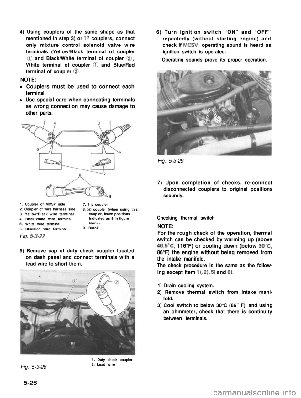
4) Using couplers of the same shape as that
mentioned in step 3) or 1P couplers, connect
only mixture control solenoid valve wire
terminals (Yellow/Black terminal of coupler
@ and Black/White terminal of coupler 0,
White terminal of coupler @ and Blue/Red
terminal of coupler 0.
NOTE:
l Couplers must be used to connect each
terminal.
l Use special care when connecting terminals
as wrong connection may cause damage to
other parts.
9
1. Coupler of MCSV side7. 1 p coupler2. Coupler of wire harness side8. 5p coupler (when using this3. Yellow/Black wire terminalcoupler, leave positions
4. Black/White wire terminalindicated as 9 in figure
,5. White wire terminalblank).
6. Blue/Red wire terminal9. Blank
Fig. 5-3-27
5) Remove cap of duty check coupler located
on dash panel and connect terminals with a
lead wire to short them.
6) Turn ignition switch “ON” and “OFF”
repeatedly (without starting engine) and
check if MCSV. operating sound is heard as
ignition switch is operated.
Operating sounds prove its proper operation.
Fig. 5-3-29
7) Upon completion of checks, re-connect
disconnected couplers to original positions
securely.
Checking thermal switch
NOTE:
For the rough check of the operation, thermal
switch can be checked by warming up (above
46.5”C, 116°F) or cooling down (below 3O”C,
86°F) the engine without being removed from
the intake manifold.
The check procedure is the same as the follow-
ing except item 11, 21, 5) and 6).
1) Drain cooling system.
2) Remove thermal switch from intake mani-
fold.
3) Cool switch to below 30°C (86” F), and using
an ohmmeter, check that there is continuity
between terminals.
Fig. 5-3-28
1. Duty check coupler2. Lead wire
5-26