Page 5 of 962

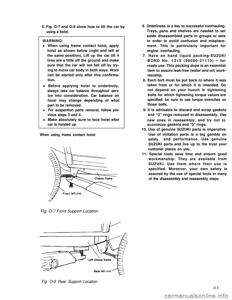
5. Fig. O-7 and O-8 show how to lift the car by
using a hoist.
WARNING:
l When using frame contact hoist, apply
hoist as shown below (right and left at
the same position), Lift up the car till 4
tires are a little off the ground and make
sure that the car will not fall off by try-
ing to move car body in both ways. Work
can be started only after this confirma-
tion.
l Before applying hoist to underbody,
always take car balance throughout serv-
ice into consideration. Car balance on
hoist may change depending of what
part to be removed.
lFor suspention parts removal, follow pre-
vious steps 3 and 4.
l Make absolutely sure to lock hoist after
car is hoisted up.
When using frame contact hoist:
6. Orderliness is a key to successful overhauling.
Trays, pans and shelves are needed to set
aside disassembled parts in groups or sets
in order to avoid confusion and misplace-
ment. This is particularly important for
engine overhauling.
7. Have on hand liquid packing-SUZUKI
BOND No. 1215 (99000-31110) - for
ready use. This packing dope is an essential
item to assure leak-free (water and oil) work-
manship.
8. Each bolt must be put back to where it was
taken from or for which it is intended. Do
not depend on your hunch in tightening
bolts for which tightening torque values are
specified: be sure to use torque wrenches on
those bolts.
9. It is advisable to discard and scrap gaskets
and “0” rings removed in disassembly. Use
new ones in reassembly, and try not to
econimize gaskets and “0” rings.
10. Use of genuine SUZUKI parts is imperative.
Use of imitation parts is a big gamble on
safetyand performance. Use genuine
SUZUKI parts and live up to the trust your
customer places on you.
11. Special tools save time and ensure good
workmanship: They are available from
SUZUKI. Use them where their use is
specified. Moreover, your own safety is
assured by the use of special tools in many
of the disassembly and reassembly steps.
Fig. O-7 Front Support Location
Fig. O-8 Rear Support Location
0-3
Page 21 of 962
![SUZUKI GRAND VITARA 1987 Service Repair Manual 1-2. ENGINE AND EMISSION CONTROL
1. WATER PUMP BELT INSPECTION
AND REPLACEMENT
[INSPECTION]
1) Disconnect negative battery lead at battery.
2) Inspect belt for cracks, cuts, deformation,
wear and clea SUZUKI GRAND VITARA 1987 Service Repair Manual 1-2. ENGINE AND EMISSION CONTROL
1. WATER PUMP BELT INSPECTION
AND REPLACEMENT
[INSPECTION]
1) Disconnect negative battery lead at battery.
2) Inspect belt for cracks, cuts, deformation,
wear and clea](/manual-img/20/57437/w960_57437-20.png)
1-2. ENGINE AND EMISSION CONTROL
1. WATER PUMP BELT INSPECTION
AND REPLACEMENT
[INSPECTION]
1) Disconnect negative battery lead at battery.
2) Inspect belt for cracks, cuts, deformation,
wear and cleanliness. If any defect, replace.
Check belt for tension. The belt is in’ proper
tension if it deflects 6 to 9 mm (0.24 - 0.35
in.) under thumb pressure (about 10 kg or
22 lb.)..
Belt tension6 - 9 mm (0.24 - 0.35 in.)
specificationas deflection
pulley
3) If the belt is too tight or too loose, adjust it
to specification by adjusting alternator
position.
4) Tighten alternator adjusting bolt and pivot
bolts.
5) Connect negative battery lead to battery.
[REPLACEMENT]
1) Disconnect negative battery lead at battery.
2) Loosen alternator adjusting bolt and pivot
bolts.
3) Replace water pump belt.
4) Adjust belt tension to specification and
tighten alternator adjusting bolt and pivot
bolts.
5) Connect negative battery lead to battery.
2. CAMSHAFT TIMING BELT INSPECTION
1) Disconnect negative battery lead at battery.
2) Loosen fan drive belt, and remove 4 bolts
securing radiator shroud panel and 4 nuts
securing engine cooling fan & clutch. Then
remove radiator shroud and cooling fan &
clutch at the same time.
3) Remove water pump belt and pump pulley.
4) Remove crankshaft pulley by removing 4
pulley bolts. The crankshaft timing belt
pulley bolt at the center need not be loosen-
ed.2 1
‘31. Key
2. Crankshaft pulley
3. Pulley bolt
1-5
Page 68 of 962
10) Remove timing belt tensioner, tensioner
plate, and tensioner spring.
11) Remove camshaft timing belt pulley by lock-
ing camshaft (insert general rod into the cam-
shaft hole) as shown below.
13) Remove crankshaft timing belt pulley key.
14) Remove timing belt inside cover.
Fig. 3-4- 14
15) Remove water pump.
1.Wrench2.Camshaft timing belt pulley
3. Timing belt inside cover4.Generalrod
Fig.3412
12) Using flywheel holder (A) (Special tool),
remove crankshaft timing belt pulley bolt,
pulley and timing belt guide with crank-
shaft locked.
Fig. 3-4- 15
16) Remove exhaust manifold cover.
17) Take off exhaust manifold and its gasket.
Fig. 3-4-13
1.Crankshaft timing belt pulley2. Pulley bolt3. Timing belt guide
Fig. 3-4- 16
3-11
Page 105 of 962

Timing Belt Inside Cover, Belt Pulleys,
Tensioner, Timing Belt and Outside Cover
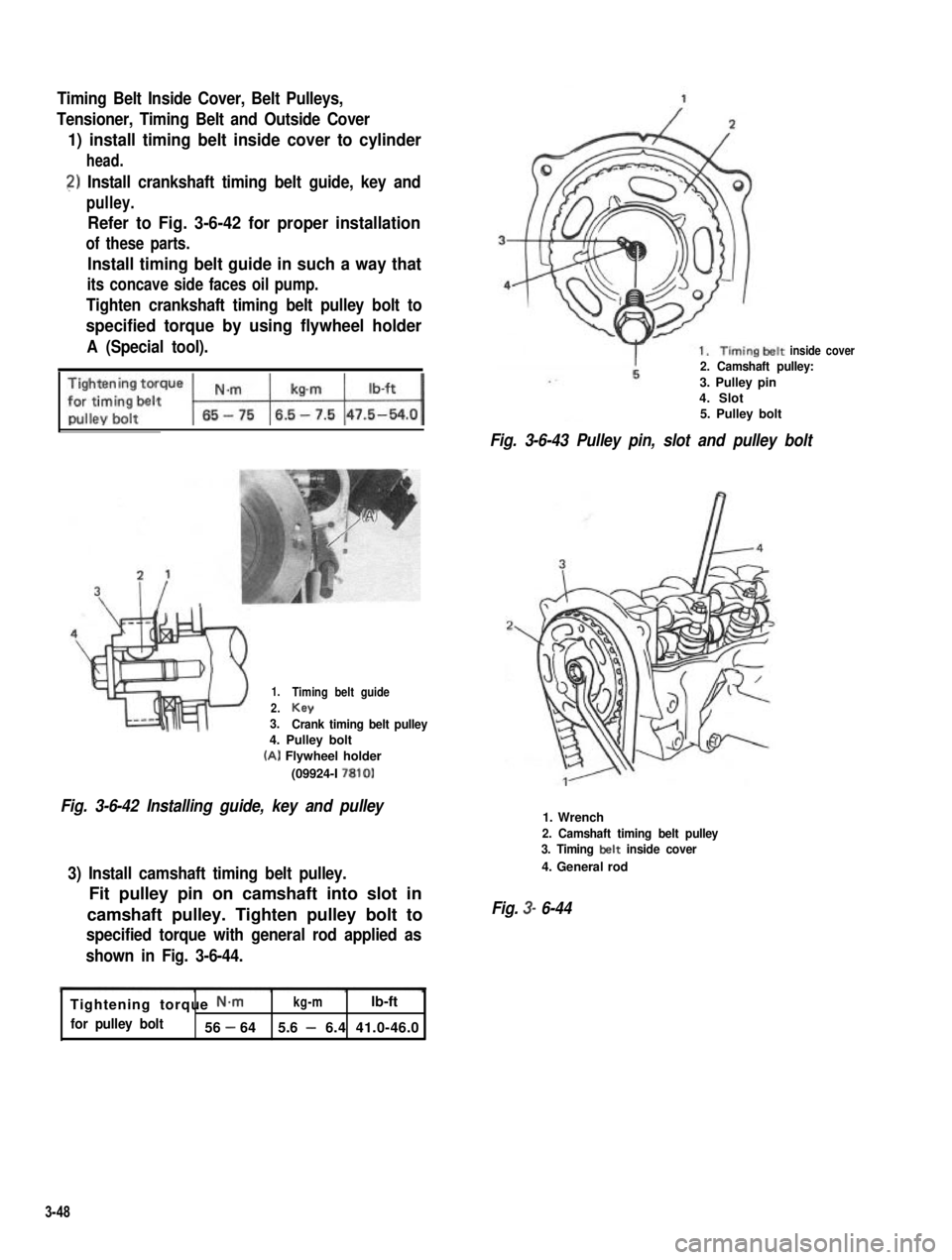
1) install timing belt inside cover to cylinder
head.
2) Install crankshaft timing belt guide, key and
pulley.
Refer to Fig. 3-6-42 for proper installation
of these parts.
Install timing belt guide in such a way that
its concave side faces oil pump.
Tighten crankshaft timing belt pulley bolt to
specified torque by using flywheel holder
A (Special tool).
1.
2.3.
Timing belt guide
KeyCrank timing belt pulley4. Pulley bolt
(A) Flywheel holder
(09924-I 7810)
Fig. 3-6-42 Installing guide, key and pulley
3) Install camshaft timing belt pulley.
Fit pulley pin on camshaft into slot in
camshaft pulley. Tighten pulley bolt to
specified torque with general rod applied as
shown in Fig. 3-6-44.
inside cover2. Camshaft pulley:
3. Pulley pin4. Slot5. Pulley bolt
Fig. 3-6-43 Pulley pin, slot and pulley bolt
1. Wrench
2. Camshaft timing belt pulley3. Timing belt inside cover
4. General rod
Fig. 3- 6-44
Tightening torque N-mkg-mlb-ft
for pulley bolt56 - 645.6 - 6.4 41.0-46.0
3-48
Page 107 of 962

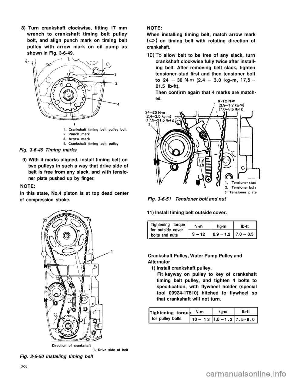
8) Turn crankshaft clockwise, fitting 17 mm
wrench to crankshaft timing belt pulley
bolt, and align punch mark on timing belt
pulley with arrow mark on oil pump as
shown in Fig. 3-6-49.
1. Crankshaft timing belt pulley bolt2. Punch mark3. Arrow mark
4. Crankshaft timing belt pulley
Fig. 3-6-49 Timing marks
9) With 4 marks aligned, install timing belt on
two pulleys in such a way that drive side of
belt is free from any slack, and with tensio-
ner plate pushed up by finger.
NOTE:
In this state, No.4 piston is at top dead center
of compression stroke.
NOTE:
When installing timing belt, match arrow mark
(+I on timing belt with rotating direction of
crankshaft.
10)To allow belt to be free of any slack, turn
crankshaft clockwise fully twice after install-
ing belt. After removing belt slack, tighten
tensioner stud first and then tensioner bolt
to 24 - 30 N.m (2.4 - 3.0 kg-m, 17,5 -
21.5 lb-ft).
Then confirm again that 4 marks are match-
ed.9-12 N-m
3. Tensioner plate
Fig. 3-6-51Tensioner bolt and nut
11) Install timing belt outside cover.
Tightening torque
for outside coverN.mkmlb-ft
bolts and nuts9- 120.9 - 1.27.0 - 8.5
Crankshaft Pulley, Water Pump Pulley and
Alternator
1) Install crankshaft pulley.
Fit keyway on pulley to key of crankshaft
timing belt pulley, and tighten 4 bolts to
specification, with flywheel holder (special
tool 09924-17810) hitched to flywheel so
that crankshaft will not turn.
Tightening torque N.mkg-mlb-ft
for pulley boltslo- 13 1.3 7.5-9.0*
Direction of crankshaft1. Drive side of belt
Fig. 3-6-50 Installing timing belt
3-50
Page 108 of 962
-1. Key
‘32. Crankshaft pulley3. Pulley bolt
Fig. 3-6-52 Installing crankshaft pulley
2) Install alternator assembly.
Tighten alternator ass’y securing bolts (3pcs)
only to the extent to allow alternator to be
moved by hand. Don’t torque them tight.
NOTE:
Adjust water pump belt tension to specification
upon completion of installing engine ass’y to
body and then cooling fan and water pump
pulley. Make sure to refer to p. 1-5 of this
manual for adjusting procedure.
Distributor Case
1) Install distributor case O-ring to cylinder
head.
2) Install distributor case.
3) Tighten bolts to specified torque.
Tightening torque N.mkg-mlb-ft
forcasebolts8-120.8-1.26.0-8.5
Fig. 3-6-53
Fuel Pump
Install fuel pump rod, gasket and fuel pump to
cylinder head.
Apply engine oil to rod @ before installation.
Use new gasket.
Fig. 3-6-54 Fuel pump rod installation
case with about 3Occ (1.02/1.05 US/Imp
3-51
Page 262 of 962

SECTION 13
TRANSMISSION
CONTENTS
13-l. GENERAL DESCRIPTION..................................13-1
TRANSMISSION GEAR RATIO..............................13-3
13-3. DISMOUNTING...........................................13-4
DISASSEMBLY............................................13-5
13-5. INSPECTION OF COMPONENTS............................13-12
13-6. IMPORTANT STEPS IN INSTALLATION.....................13-15
13-7. MAINTENANCE SERVICES................................13-25
13-8. RECOMMENDED TORQUE SPECIFICATION.................. 13-26
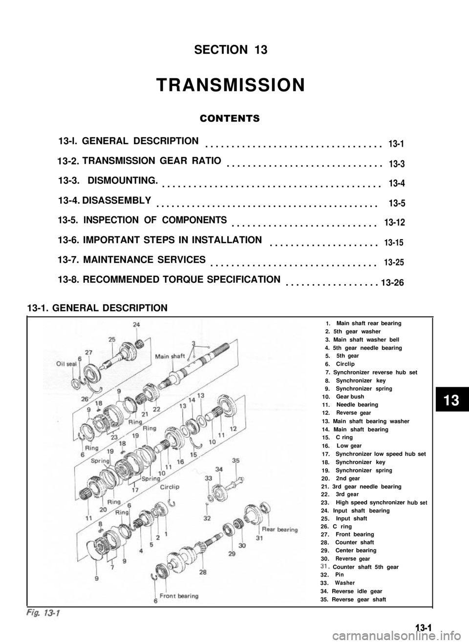
13-1. GENERAL DESCRIPTION
241.Main shaft rear bearing
2. 5th gear washer
3. Main shaft washer bell
4. 5th gear needle bearing
Oil sealfiMain shi5.5thgear
6.ICirclip
7. Synchronizer reverse hub set
8.Synchronizer key
9.Synchronizerspring
10.Gear bush
11.Needle bearing
12.Reversegear
13. Main shaft bearing washer
14. Main shaft bearing15.C ring
16.Lowgear
17.Synchronizer low speed hub set
18.Synchronizerkey
19.Synchronizerspring
20.2ndgear
F21. 3rd gear needle bearing22.3rdgear
23.hub
I
1High speed synchronizerset
I
24. Input shaft bearing25.Input shaft
i ’
IL’
ear bearing26. C ring27.AFront bearing
28.Counter shaft
429.Center bearing
930.ReversegearI i31. Counter shaft 5th gear
932.Pin
33.Washer
34. Reverse idle gear
35. Reverse gear shaft
13-1
13-2.
13-4.
13
Page 273 of 962
13-5. INSPECTION OF COMPONENTS
Gears
Check each part for wear, damage or discolora-
tion. Replace if found defective.
Fig. 13-31
Fig. 13-29
Synchronizer Hubs, Sleeves and Keys
Check each part for wear or damage. Replace if
found defective.
Fig. 13-30
Shift Forks and Sleeves
Check contact surfaces for wear or damage.
Measure clearance between fork and sleeve.
IMaximum clearancej 1.0 mm (0.039 in) 1
Main Shaft
Check each part of shaft for wear, discoloration
or damage. Replace shaft if any part is found
defective.
Fig. 13-32
Bearings and Bushes
Check each part for wear, damage or discolora-
tion. With ball bearing, check to ensure that it
rotates smoothly and it does not make noise.
Replace if found defective.
Fig. 13-33
13-12