Page 173 of 962

[Jet1
1) Remove jet.
2) When blowing air into pipe 0, air should
come out of pipe 0.
Replace clogged jet.
3) Install jet with its gray side directed toward
MCV.
1. Pipe (Gray side)2.Pipe
33.Jet
Fig.53-134.Blowair
FEED BACK SYSTEM
Whether feed back system including oxygen sensor and ECM (Electronic Control Module) is in good
condition or not, can be judged by checking for operation of “CHECK ENGINE” light in instrument clus-
ter..
[U.S.A. specification vehicle]
As previously outlined,“CHECK ENGINE” light automatically flashes at 50,000 miles, 80,000 miles and
100,000 miles indicated on odometer when running warmed up engine. And this automatical flashing at
above mileages proves that system is in good condition.
Should any of following malcondition occur, the system check can be .performed according to “System
check flow chart”,even when mileage indicated by odometer is not any of 50,000 miles, 80,000 miles
and 100,000 miles.
[Canadian specification vehicle]
Should any of following malconditions occur, the system check can be performed according to “System
check flow chart”.
l Fuel consumption increases excssively even in normal driving.
l Engine tends to stall.
l Engine is hard to start.
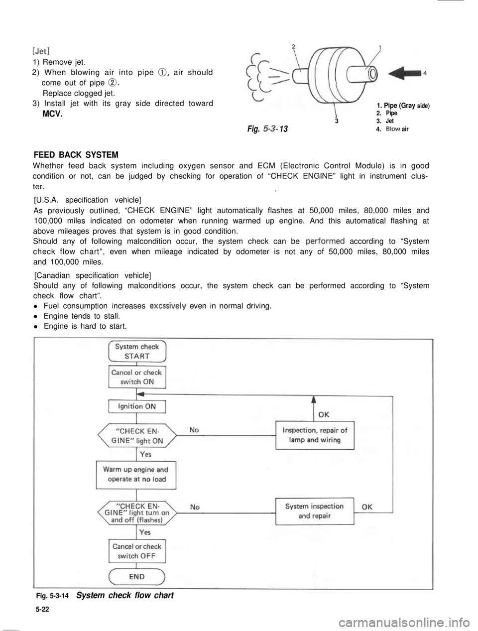
System check
STARTI
Cancel or check
switch ON
“CHECK EN-
Yes
Inspection, repair of
lamp and wiring1
Warm up engine and
operate at no load
I
“CHECK EN-GINE”light turnonand off (flashes)I
NoSystem inspection OK
and repair
Cancel or check
Fig. 5-3-14System check flow chart
5-22
Page 184 of 962

[Checking function of oxygen sensor and feed back system1
If oxygen sensor fails to send signal to the ECM, the feed back system does not operate. While the feed
back system is at work, the ECM sends out the feed back signal, and in this condition, after warming up
engine to normal operating temperature, when the cancel switch or check switch, is turned ON, the “CHECK
ENGINE” light in the instrument cluster flashes. If the “CHECK ENGINE” light does not flash in such
conditions as described above, check the feed back system for function according to the following pro-
cedure.
NOTE:
Except for Canadian specification vehicle, also when mileage sensor is turned ON (the odometer indicates
50,000, 80,000 or 100,000 miles), the “CHECK ENGINE” light flashes. If the “CHECK ENGINE” light
does not flash in such condition, check the feed back system for function according to the following
procedure.
1) Remove the ECM from the instrument main panel.
2) Connect the coupler to the ECM..
(Don’t disconnect the coupler from the ECM if connected)
3) Warm up the engine to the normal operating temperature and keep it at idle.
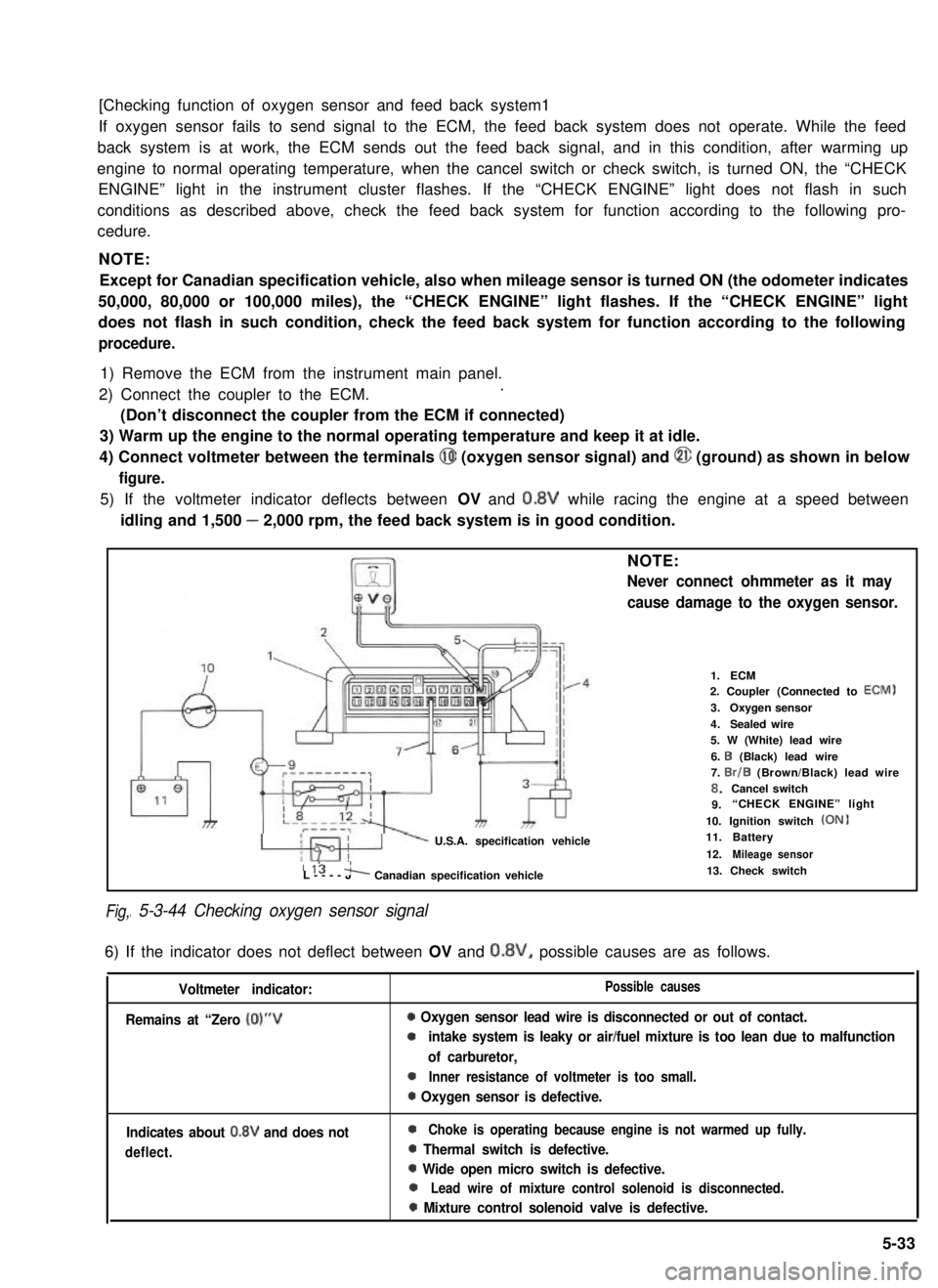
4) Connect voltmeter between the terminals @I (oxygen sensor signal) and @ (ground) as shown in below
figure.
5) If the voltmeter indicator deflects between OV and 0.8V while racing the engine at a speed between
idling and 1,500 - 2,000 rpm, the feed back system is in good condition.
Fig,
NOTE:
Never connect ohmmeter as it may
cause damage to the oxygen sensor.
U.S.A. specification vehicle
1.ECM2. Coupler (Connected to ECM)
3.Oxygen sensor
4.Sealed wire5. W (White) lead wire
6. I3 (Black) lead wire7. Br/B (Brown/Black) lead wire8.Cancel switch9.“CHECK ENGINE” light
10. Ignition switch (ON)11.Battery
12.Mileage sensor115 'L----JA Canadian specification vehicle
I 5-3-44 Checking oxygen sensor signal
13. Check switch
6) If the indicator does not deflect between OV and 0.8V, possible causes are as follows.
Voltmeter indicator:
Remains at “Zero (0)“V
Possible causes
0 Oxygen sensor lead wire is disconnected or out of contact.
0intake system is leaky or air/fuel mixture is too lean due to malfunction
of carburetor,
0Inner resistance of voltmeter is too small.
0 Oxygen sensor is defective.
Indicates about 0.8V and does not
deflect.
0Choke is operating because engine is not warmed up fully.
0 Thermal switch is defective.
0 Wide open micro switch is defective.
0Lead wire of mixture control solenoid is disconnected.
0 Mixture control solenoid valve is defective.
5-33
Page 185 of 962

7) After it isconfirmed through steps 1) to 5) that oxygen sensor sends signals to ECM properly, check feed
back signal according to the following procedure. If feed back system operates properly, ECM should
send out feed back signal.
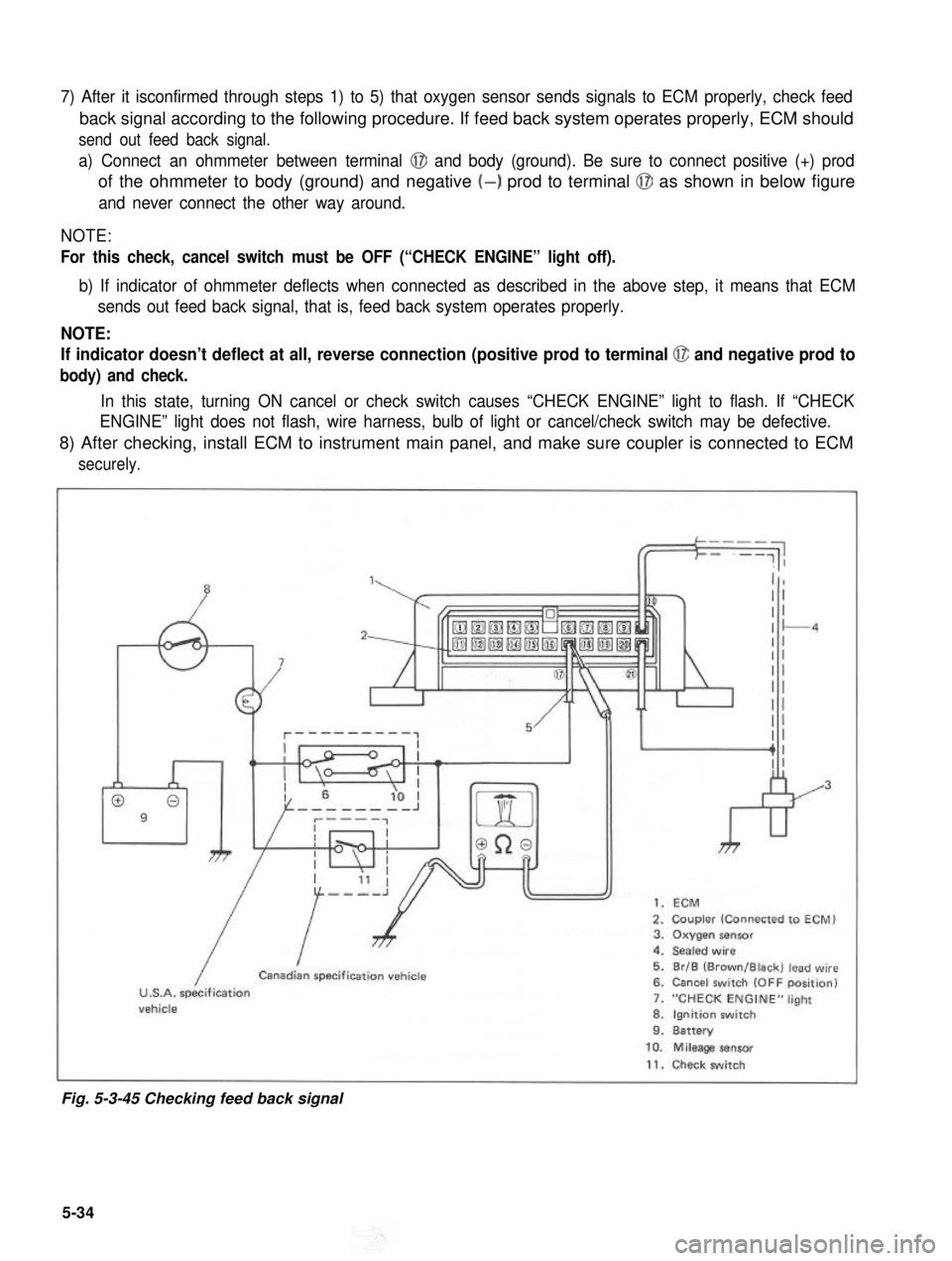
a) Connect an ohmmeter between terminal @I and body (ground). Be sure to connect positive (+) prod
of the ohmmeter to body (ground) and negative (-) prod to terminal @J as shown in below figure
and never connect the other way around.
NOTE:
For this check, cancel switch must be OFF (“CHECK ENGINE” light off).
b) If indicator of ohmmeter deflects when connected as described in the above step, it means that ECM
sends out feed back signal, that is, feed back system operates properly.
NOTE:
If indicator doesn’t deflect at all, reverse connection (positive prod to terminal @ and negative prod to
body) and check.
In this state, turning ON cancel or check switch causes “CHECK ENGINE” light to flash. If “CHECK
ENGINE” light does not flash, wire harness, bulb of light or cancel/check switch may be defective.
8) After checking, install ECM to instrument main panel, and make sure coupler is connected to ECM
securely.
”1,
009
7
kr
1. ECM
2. Coupler (Connected to ECM)3. Oxygen sensor4. Sealed wire
5. Br/B (Brown/Black) lead wire6. Cancel switch (OFF position)
7. “CHECK ENGINE” light
8. Ignition switch9. Battery
/
ICanadian specification vehicle
U.S.A. specificationvehicle
10. Mileage sensor
11. Check switch
Fig. 5-3-45 Checking feed back signal
5-34