Page 219 of 962

Ignition Timing
Ignition timing10” BTDC at
800 * 50 r/min
1 Ignition orderIl-3-4-2I
When checking and adjusting ignition timing,
be sure to use timing light (09900-27301 or
09900-27311).
NOTE:
Prior to check and adjustment of ignition timing,
make sure that head lights, heater fan, rear
defogger (if equipped), and air conditioner (if
equipped) are “OFF”. If any one of these
systems is “ON”,idle up system operates and
engine idle speed will be out of the specification.
[Checking]
1. Remove rubber plug from timing check
window on the transmission case.
2. Start engine and warm it up to normal operat-
ing temperature.
3. After warming up, check to be sure that idle
speed is within specification. If idle speed is
out of specification, adjust it by turning
idle speed adjusting screw of carburetor.
4. Connect timing light to high tension cord of
No. 1 cylinder.
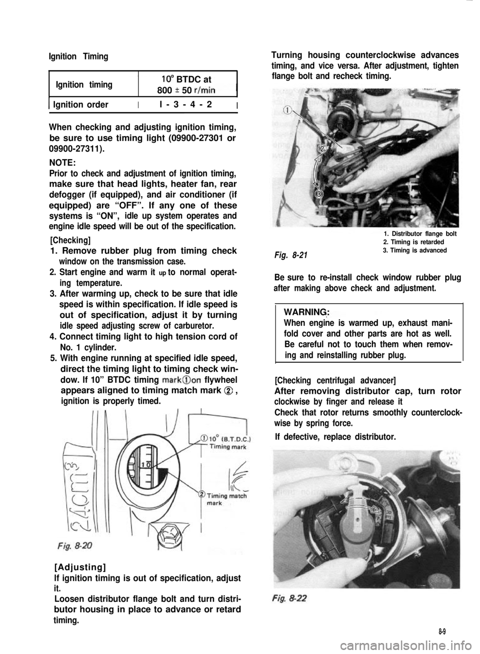
5. With engine running at specified idle speed,
direct the timing light to timing check win-
dow. If 10” BTDC timing mark@on flywheel
appears aligned to timing match mark @ ,
ignition is properly timed.
Fig. 8-20
[Adjusting]
lf ignition timing is out of specification, adjust
it.
Loosen distributor flange bolt and turn distri-
butor housing in place to advance or retard
timing.
Turning housing counterclockwise advances
timing, and vice versa. After adjustment, tighten
flange bolt and recheck timing.
Fig. 8-21
1. Distributor flange bolt
2. Timing is retarded
3. Timing is advanced
Be sure to re-install check window rubber plug
after making above check and adjustment.
WARNING:
When engine is warmed up, exhaust mani-
fold cover and other parts are hot as well.
Be careful not to touch them when remov-
ing and reinstalling rubber plug.
[Checking centrifugal advancer]
After removing distributor cap, turn rotor
clockwise by finger and release it
Check that rotor returns smoothly counterclock-
wise by spring force.
If defective, replace distributor.
Fig. 8-22
8-9
Page 427 of 962

19-8. MAINTENANCE SERVICE
ROAD TESTING BRAKES
Brakes should be tested on dry, clean, smooth
and reasonably level roadway which is not
crowned. Road test brakes by making brake
applications with both light and heavy pedal
forces at various speeds to determine if the car
stops evenly and effectively.
Also drive car to see if it leads to one side or the
other without brake application. If it does,
check tire pressure, front end alignment and
front suspension attachments for looseness.
See diagnosis chart for other causes.
BRAKE FLUID LEAKS
Check master cylinder fluid levels. While a slight
drop in reservoir level does result from normal
lining wear, an abnormally low level indicates a
leak in the system.In such a case, check the
entire brake system for leakage. If even a slight
evidence of leakage is noted, the cause should be
corrected or defective parts should be replaced.
BRAKE FLUID LEVEL INSPECTION
Be sure to use particular brake fluid either as
marked on reservoir cap of that car or recom-
mended in owner’s manual which comes along
with that car.
Use of any other fluid is strictly prohibited.
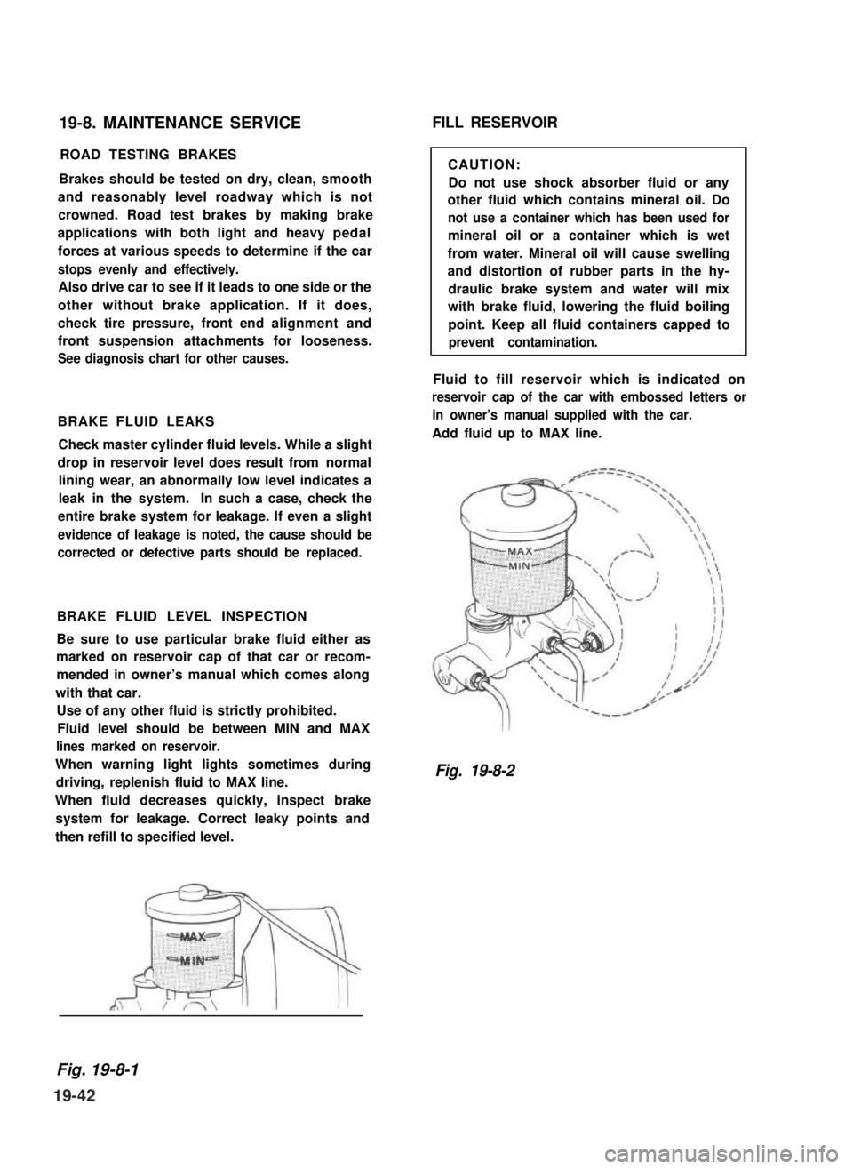
Fluid level should be between MIN and MAX
lines marked on reservoir.
When warning light lights sometimes during
driving, replenish fluid to MAX line.
When fluid decreases quickly, inspect brake
system for leakage. Correct leaky points and
then refill to specified level.
FILL RESERVOIR
CAUTION:
Do not use shock absorber fluid or any
other fluid which contains mineral oil. Do
not use a container which has been used for
mineral oil or a container which is wet
from water. Mineral oil will cause swelling
and distortion of rubber parts in the hy-
draulic brake system and water will mix
with brake fluid, lowering the fluid boiling
point. Keep all fluid containers capped to
prevent contamination.
Fluid to fill reservoir which is indicated on
reservoir cap of the car with embossed letters or
in owner’s manual supplied with the car.
Add fluid up to MAX line.
Fig. 19-8-2
Fig. 19-8-1
19-42
Page 455 of 962

INSPECTION
1) Trouble diagnosis
Symptom
1. Lights will not come on in either left or
right group of light.
2. Hazard light comes on but turn signal
lights will not.
3. No light comes on; or lights light up but
do not flicker.
4. Turn signal lights are satisfactory, but
hazard light will not come on.
5. Flickering freueqncy is erratic, or lights
remain lit.
6. Turning on hazard warning switch lights up
only one group of lights.
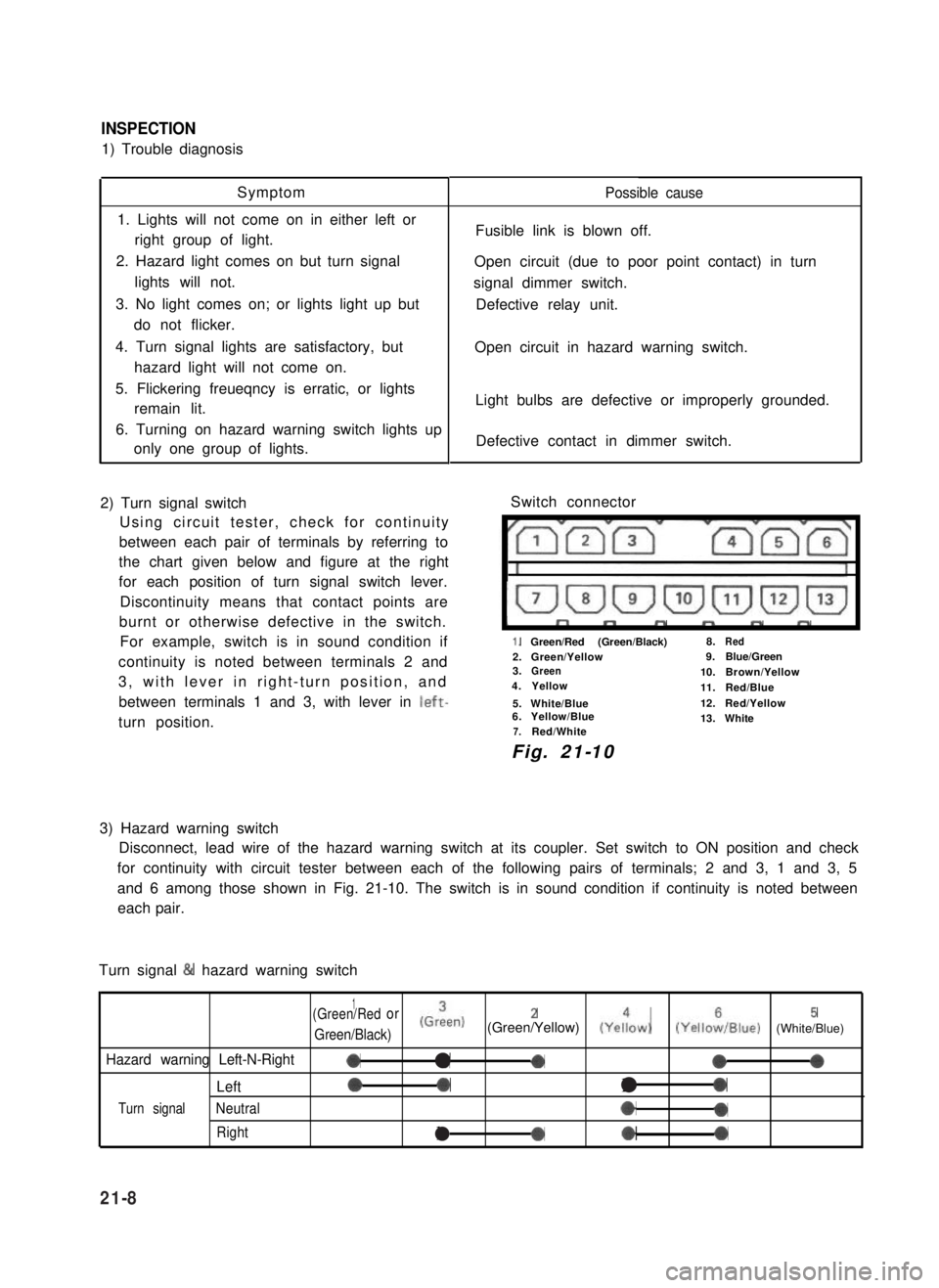
2) Turn signal switch
Using circuit tester, check for continuity
between each pair of terminals by referring to
the chart given below and figure at the right
for each position of turn signal switch lever.
Discontinuity means that contact points are
burnt or otherwise defective in the switch.
For example, switch is in sound condition if
continuity is noted between terminals 2 and
3, with lever in right-turn position, and
between terminals 1 and 3, with lever in left-
turn position.
Possible cause
Fusible link is blown off.
Open circuit (due to poor point contact) in turn
signal dimmer switch.
Defective relay unit.
Open circuit in hazard warning switch.
Light bulbs are defective or improperly grounded.
Defective contact in dimmer switch.
Switch connector
I”””yrm-
1.Green/Red (Green/Black)8.Red
2.Green/Yellow9.Blue/Green3.Green10.Brown/Yellow4.Yellow11.Red/Blue
5.White/Blue12.Red/Yellow6.Yellow/Blue13.White7.Red/White
Fig. 21-10
3) Hazard warning switch
Disconnect, lead wire of the hazard warning switch at its coupler. Set switch to ON position and check
for continuity with circuit tester between each of the following pairs of terminals; 2 and 3, 1 and 3, 5
and 6 among those shown in Fig. 21-10. The switch is in sound condition if continuity is noted between
each pair.
Turn signal & hazard warning switch
1(Green/Redor
Green/Black)
(Grien)2(Green/Yellow) (Yeiow)5(YelloiIBlue) (White/Blue)
Hazard warning Left-N-Right0a-000
Left00l0
Turn signalNeutral*0
Rightla*0
21-8