1987 SUZUKI GRAND VITARA recommended oil
[x] Cancel search: recommended oilPage 20 of 962
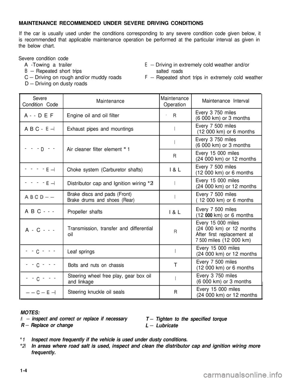
MAINTENANCE RECOMMENDED UNDER SEVERE DRIVING CONDITIONS
If the car is usually used under the conditions corresponding to any severe condition code given below, it
is recommended that applicable maintenance operation be performed at the particular interval as given in
the below chart.
Severe condition code
A -Towing a trailer
B- Repeated short trips
C - Driving on rough and/or muddy roads
D - Driving on dusty roads
E- Driving in extremely cold weather and/or
salted roads
F- Repeated short trips in extremely cold weather
Severe
Condition CodeMaintenanceMaintenance
OperationMaintenance Interval
A--DEFEngine oil and oil filter_ REvery 3 750 miles
(6 000 km) or 3 months
ABC- E-Exhaust pipes and mountingsIEvery 7 500 miles
(12 000 km) or 6 months
IEvery 3 750 miles
D(6 000 km) or 3 months--- --Air cleaner filter element * 1
REvery 15 000 miles
(24 000 km) or 12 months
----E-Choke system (Carburetor shafts)I&LEvery 7 500 miles
(12 000 km) or 6 months
----E-Distributor cap and Ignition wiring “2IEvery 15 000 miles
(24 000 km) or 12 months
ABCD--Brake discs and pads (Front)IEvery 7 500 miles
Brake drums and shoes (Rear)( 12 000 km) or 6 months
ABC---Propeller shaftsI&LEvery 7 500 miles
(12 000 km) or 6 months
Every 15 000 miles
A-C---Transmission, transfer and differential(24 000 km) or 12 months
oilRAfter first replacement at
7 500 miles (12 000 km)
CEvery 15 000 miles-- ---’ Leaf springsI(24 000 km) or 12 months
C-- ---Bolts and nuts on chassisTEvery 7 500 miles
(12 000 km) or 6 months
CSteering wheel free play, gear box oil-- ---and linkageIEvery 3 750 miles
(6 000 km) or 3 months
--C-E-Steering knuckle oil sealsREvery 15 000 miles
(24 000 km) or 12 months
MOTES:
I- inspect and correct or replace if necessary
R - Replace or change
T - Tighten to the specified torque
L - Lubricate
* 1Inspect more frequently if the vehicle is used under dusty conditions.
*2In areas where road salt is used, inspect and clean the distributor cap and ignition wiring more
frequently.
1-4
Page 23 of 962
NOTE:
Steps 1) - 6) outlined above must be performed
with ENGINE NOT RUNNING. For step 7),
be sure to have adequate ventilation while
engine is running
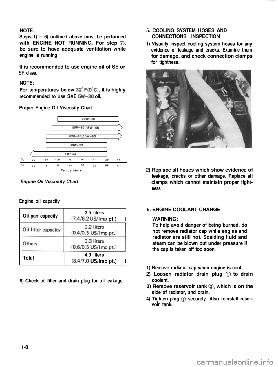
It is recommended to use engine oil of SE or
SF class.
NOTE:For temperatures below
32”F(O”C), it is highly
recommended to use SAE 5W-30 oil.
Proper Engine Oil Viscosity Chart
12OW-50
lSW-40.15w-501
Ilow-4O.lOW-50
Ilow-30I
5w-30I“C-3 0 -2
0 -1
0 0 102
0
30 4
0
OF-2 2 -
4 14
32506886104
Temperatur e
Engine Oil Viscosity Chart
Engine oil capacity
Oil pan capacity 3.5 liters (7.4/6.2
US/Imp pt.)I
Total 4.0 liters(8.4/7.0 US/Imp pt.)I
8) Check oil filter and drain plug for oil leakage.
5. COOLING SYSTEM HOSES AND
CONNECTIONS INSPECTION
1) Visually inspect cooling system hoses for any
evidence of leakage and cracks. Examine them
for damage, and check connection clamps
for tightness.
2) Replace all hoses which show evidence of
leakage, cracks or other damage. Replace all
clamps which cannot maintain proper tight-
ness.
6. ENGINE COOLANT CHANGE
WARNING:
To help avoid danger of being burned, do
not remove radiator cap while engine and
radiator are still hot. Scalding fluid and
steam can be blown out under pressure if
the cap is taken off too soon.
1) Remove radiator cap when engine is cool.
2) Loosen radiator drain plug @
to drain
coolant.
3) Remove reservoir tank 0, which is on the
side of radiator, and drain.
4) Tighten plug
@ securely. Also reinstall reser-
voir tank.
1-8
Page 36 of 962
3) Check propeller shaft (No. 1, No. 2, No. 3)
flange yoke bolts for tightness, and retighten
them as necessary:
N.mkg-mlb-ftTighteningtorque23-302.3-3.017.0-21.5
42. TRANSMISSION, TRANSFER,
DIFFERENTIAL OIL INSPECTION
AND CHANGE
[I nspectionl
1) Inspect transmission case, transfer case and
differential housing for evidence of oil leakage.
Repair leaky point if any.
2) Make sure that the car is placed level for oil
level check.
3) Remove each level plug of transmission,
transfer and differential (front and rear).
In any of these cases, oil level can be checked
roughly by means of level plug hole. That is,
,if oil flows out of level plug hole or if oil
level is found up to hole when level plug is
removed, oil is properly filled.
If oil is found insufficient, pour specified
amount of specified oil as given in the below
table.
[Change]
Oil change procedure is as follows.
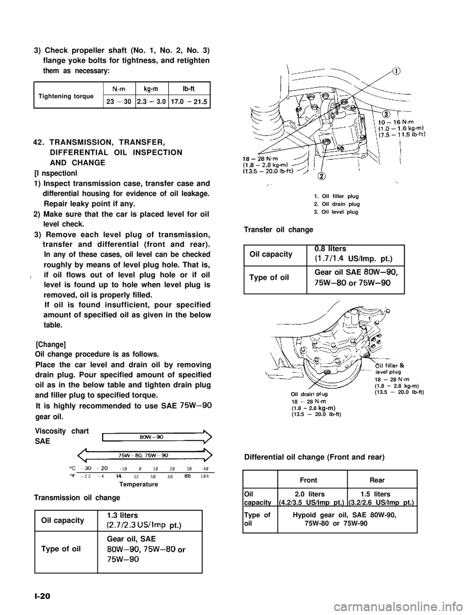
Place the car level and drain oil by removing
drain plug. Pour specified amount of specified
oil as in the below table and tighten drain plug
and filler plug to specified torque.
It is highly recommended to use SAE 75W-90
gear oil.
Viscosity chart
SAE
75w-ao,75w-90
"C -30 --20 -10 0 10 20 30 40"F -22 -4lb 32 50 68 86104
Temperature
Transmission oil change
Oil capacity
Type of oil
1.3 liters
(2.7/2.3 US/Imp pt.)
Gear oil, SAE
8OW-90,75W-80 or
75w-90
l-20
18-28N.m
I ”’
1. Oil filler plug
2. Oil drain plug
3. Oil level plug
Transfer oil change
Oil capacity0.8 liters
(1.7/l .4 US/Imp. pt.)
Type of oilGear oil SAE 8OW-90,
75W-80 or 75W-90
18 - 28 N.m(1.8 - 2.8 kg-m)(13.5 - 20.0 lb-ft)-R-Oil drair18 - 28 N&(1.8 - 2.8 kg-m)(13.5 - 20.0 lb-ft)
Differential oil change (Front and rear)
1.5 liters
(3.2/2.6 US/Imp pt.)
2.0 liters
(4.2/3.5 US/Imp pt.)
FrontRear
Oil
capacity
Type of
oil
Hypoid gear oil, SAE 80W-90,
75W-80 or 75W-90
Page 115 of 962
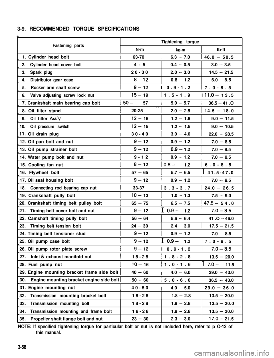
3-9. RECOMMENDED TORQUE SPECIFICATIONS
Fastening partsN-m
Tightening torque
kg-mlb-ft
1. Cylinder head bolt1 63-7016.3 - 7.01 46.0 - 50.5
2.Cylinder head cover bolt4-50.4-0.53.0-3.5
3.Spark plug20-302.0-3.014.5-21.5
4.Distributor gear case8-120.8-1.26.0-8.5
5.Rocker arm shaft screwI9- 12I 0.9-1.21 7.0-8.5
6.Valve adjusting screw lock nut
7. Crankshaft main bearing cap bolt
8. Oil filter stand
I15- 191 1.5-1.9I ll.O- 13.5
1 50- 5715.0 - 5.7136.5 - 41 .O
I20-25 -. 12.0 - 2.51 14.5 - 18.0
9.Oilfilter Ass’y12-161.2-1.69.0-11.5
10.Oilpressure switch12-151.2-1.59.0-10.5
11. Oil drain plugI30-40I3.0 - 4.0122.0 - 28.5
12. Oil pan bolt and nutI9- 12I0.9 - 1.2I7.0 - 8.5
13. Oil pump strainer bolt
14. Water pump bolt and nut
I9- 12I0.9 - 1.2I7.0 - 8.5
I9-12I0.9 - 1.2I7.0 - 8.5
15. Cooling fan nutI8- 121 0.8- 1.21 6.0-8.5
16. Flywheel boltI57 - 65I5.7 - 6.5I 41.5-47.0
17. Oil seal housing boltI9- 12I0.9 - 1.2I7.0 - 8.5
18.Connecting rod bearing cap nut1 33-37( 3.3-3.71 24.0 - 26.5
19. Crankshaft pully boltIlo- 13I1.0 - 1.3I7.5 - 9.0
20. Crankshaft timing belt pulley bolt
21.Timing belt cover bolt and nut
I65 - 75I6.5 - 7.51 47.5- 54.0
I9- 12I 0.9- 1.21 7-O-8.5
22. Camshaft timing pully boltI56 - 6415.6 - 6.4141 .O - 46.0III
23.Timingbelttensionbolt24-302.4-3.0117.5-21.5
24. Timing belt tensioner studI9- 12I0.9 - 1.2I7.0 - 8.5
25. Oil pump case boltI‘9- 12I 0.9- 1.21 7.0-8.5
26. Oil pump rotor plate screwI9- 12I 0.9-1.21 7-O-8.5
27.Inlet & exhaust manifold nutI18-281 1.8-2.8I13.5 - 20.0
28. Fuel pump nutIlo- 161 1.0-1.6I 7.0- 11.5
29. Engine mounting bracket frame side bolt 140 - 60I ~~~4.0 - 6.0129.0 - 43.0
30.Engine mounting bracket engine side bolt I50 - 601 5.0-6.0136.5 - 43.0
31. Engine mounting nutI40-50I4.0 - 5.01 29.0 - 36.0I1I
32.Transmissionmountingbracketbolt18-281.8-2.8113.5-20.0
33.Transmission mounting bolt18-281.8-2.813.5 -20.0
34.Transmission mounting and framebolt18-281.8-2.813.5 -20.0
35.Propeller shaft flange bolt and nut23 - 302.3-3.017.0-21.5
NOTE: If specified tightening torque for particular bolt or nut is not included here, refer to p O-12 of
this manual.
3-58
Page 193 of 962
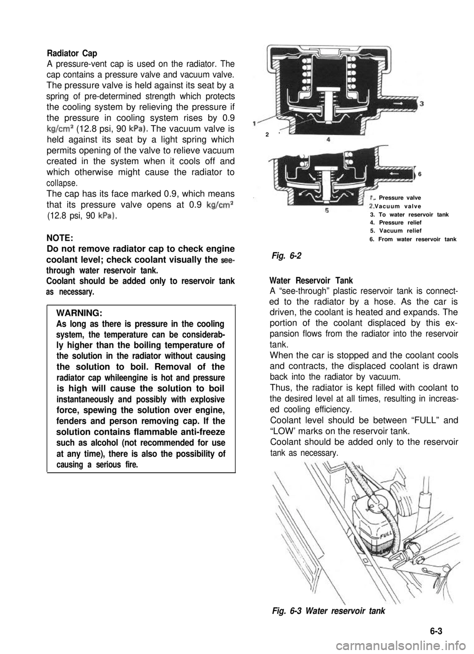
Radiator Cap
A pressure-vent cap is used on the radiator. The
cap contains a pressure valve and vacuum valve.
The pressure valve is held against its seat by a
spring of pre-determined strength which protects
the cooling system by relieving the pressure if
the pressure in cooling system rises by 0.9
kg/cm2 (12.8 psi, 90 kPa). The vacuum valve is
held against its seat by a light spring which
permits opening of the valve to relieve vacuum
created in the system when it cools off and
which otherwise might cause the radiator to
collapse.
The cap has its face marked 0.9, which means
that its pressure valve opens at 0.9 kg/cm2
(12.8 psi, 90 kPa).
NOTE:
Do not remove radiator cap to check engine
coolant level; check coolant visually the see-
through water reservoir tank.
Coolant should be added only to reservoir tank
as necessary.
4
WARNING:
As long as there is pressure in the cooling
system, the temperature can be considerab-
ly higher than the boiling temperature of
the solution in the radiator without causing
the solution to boil. Removal of the
radiator cap whileengine is hot and pressure
is high will cause the solution to boil
instantaneously and possibly with explosive
force, spewing the solution over engine,
fenders and person removing cap. If the
solution contains flammable anti-freeze
such as alcohol (not recommended for use
at any time), there is also the possibility of
causing a serious fire.
2’
I6
. Pressure valve
Vacuum valve
3. To water reservoir tank4. Pressure relief5. Vacuum relief
6. From water reservoir tank
Fig. 6-2
Water Reservoir Tank
A “see-through” plastic reservoir tank is connect-
ed to the radiator by a hose. As the car is
driven, the coolant is heated and expands. The
portion of the coolant displaced by this ex-
pansion flows from the radiator into the reservoir
tank.
When the car is stopped and the coolant cools
and contracts, the displaced coolant is drawn
back into the radiator by vacuum.
Thus, the radiator is kept filled with coolant to
the desired level at all times, resulting in increas-
ed cooling efficiency.
Coolant level should be between “FULL” and
“LOW’ marks on the reservoir tank.
Coolant should be added only to the reservoir
tank as necessary.
Fig. 6-3 Water reservoir tank
6-3
Page 262 of 962
SECTION 13
TRANSMISSION
CONTENTS
13-l. GENERAL DESCRIPTION..................................13-1
TRANSMISSION GEAR RATIO..............................13-3
13-3. DISMOUNTING...........................................13-4
DISASSEMBLY............................................13-5
13-5. INSPECTION OF COMPONENTS............................13-12
13-6. IMPORTANT STEPS IN INSTALLATION.....................13-15
13-7. MAINTENANCE SERVICES................................13-25
13-8. RECOMMENDED TORQUE SPECIFICATION.................. 13-26
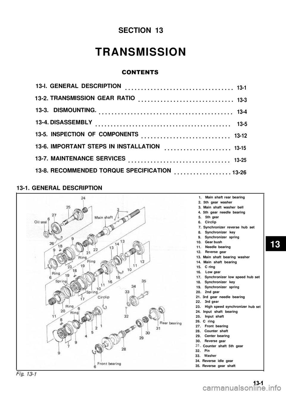
13-1. GENERAL DESCRIPTION
241.Main shaft rear bearing
2. 5th gear washer
3. Main shaft washer bell
4. 5th gear needle bearing
Oil sealfiMain shi5.5thgear
6.ICirclip
7. Synchronizer reverse hub set
8.Synchronizer key
9.Synchronizerspring
10.Gear bush
11.Needle bearing
12.Reversegear
13. Main shaft bearing washer
14. Main shaft bearing15.C ring
16.Lowgear
17.Synchronizer low speed hub set
18.Synchronizerkey
19.Synchronizerspring
20.2ndgear
F21. 3rd gear needle bearing22.3rdgear
23.hub
I
1High speed synchronizerset
I
24. Input shaft bearing25.Input shaft
i ’
IL’
ear bearing26. C ring27.AFront bearing
28.Counter shaft
429.Center bearing
930.ReversegearI i31. Counter shaft 5th gear
932.Pin
33.Washer
34. Reverse idle gear
35. Reverse gear shaft
13-1
13-2.
13-4.
13
Page 286 of 962
13-7. MAINTENANCE SERVICES
Transmission Oil
Before changing oil, check for oil leakage first
and correct defects, if any. Fill specified new oil
in specified amount.
Oil capacity1.3 litres
(2.75/2.29 US/Imp. pt.)
IOil specificationGear oil, SAE 8OW-90,75W-80
or 75W-90I
It is. highly recommended to use SAE 75W-90.
gear oil.
For viscosity chart, refer to P. I-20.
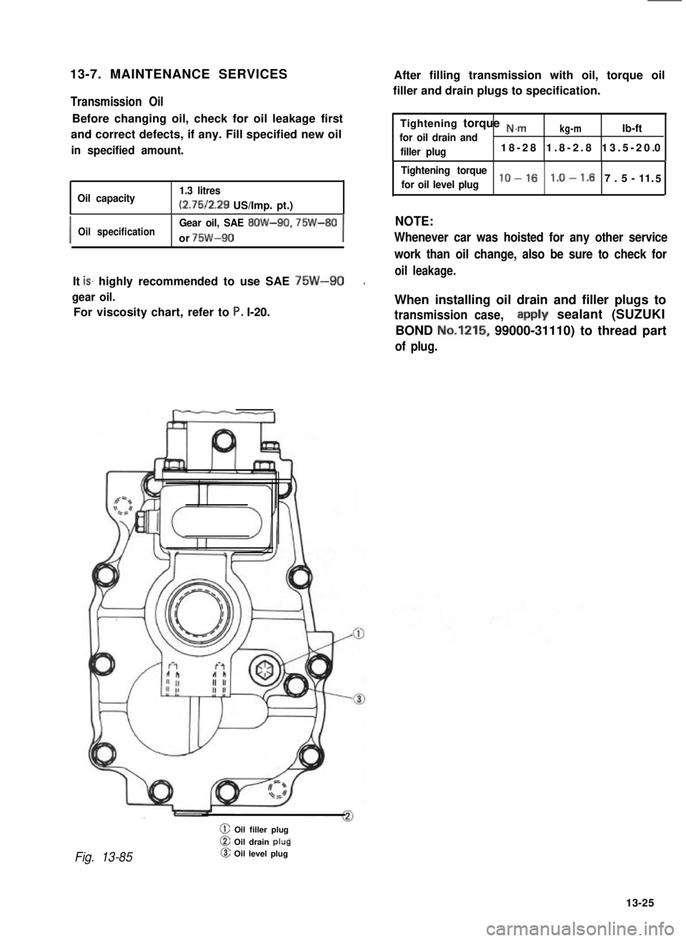
Fig. 13-85
@ Oil filler plug
@ Oil drain plup@ Oil level plug
After filling transmission with oil, torque oil
filler and drain plugs to specification.
Tightening torque N.m
for oil drain andkg-mlb-ft
filler plug18-28 1.8-2.8 13.5-20.0
Tightening torque
for oil level pluglo-161.0-1. 7.5-11.5
NOTE:
Whenever car was hoisted for any other service
work than oil change, also be sure to check for
oil leakage.
When installing oil drain and filler plugs to
transmission case,aipply sealant (SUZUKI
BOND No.1215, 99000-31110) to thread part
of plug.
13-25
Page 309 of 962
7) Install propeller shaft flanges and tighten
nuts to specified torque and talk the nuts.
8) Upon completion of entire assembly work,
install transfer in chassis body in reverse
sequence of removal. Pour gear oil into
transfer gear box.
Refer to information given in next oil and
oil capacity for oil to be used and specified
amount.
NOTE:
When installing oil filler and drain plugs to
transfer case, apply sealant (SUZUKI BOND
No.1215, 99000-31110) to thread part of plug.
14-9. MAINTENANCE SERVICES
Oil Level
Oil level must be checked with car held in
horizontal position in both front to rear and side
to side directions.
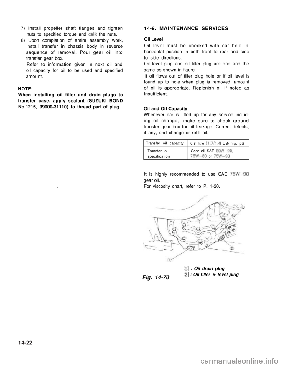
Oil level plug and oil filler plug are one and the
same as shown in figure.
If oil flows out of filler plug hole or if oil level is
found up to hole when plug is removed, amount
of oil is appropriate. Replenish oil if noted as
insufficient.
Oil and Oil Capacity
Whenever car is lifted up for any service includ-
ing oil change,make sure to check around
transfer gear box for oil leakage. Correct defects,
if any, and change or refill oil.
Transfer oil capacity0.8 litre (1.7/l .4 US/Imp. pt)
Transfer oilGear oil SAE 8OW-90,
specification75W-80 or 75W-90
It is highly recommended to use SAE 75W-90
gear oil.
For viscosity chart, refer to P. 1-20.
@ : Oil drain plug
Fig. 14-70@ : Oil filler & level plug
14-22