Page 450 of 962

Wire color
G/R . . .Green/RedOr . Orange
0 . . . . .BlackBI/B . Blue/Black
0rlB . . .Brown/Blackw . White
Y/B . . .Yellow/BlackY/R . Yellow/Red
B/W . .Black/WhiteG/Y . .Green/Yellow
W/R .White/RedY/W . . Yellow/White
RIB .Red/BlackR/Y . Red/Yellow
G. . .GreenR/G . . .Red/Green
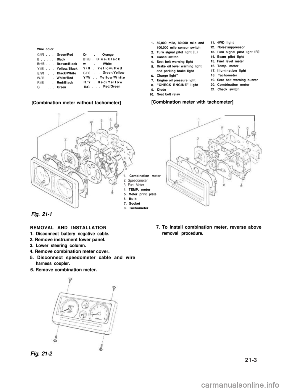
1.
2.
3.
4.
5.
6.7.
8.
9.
10.
50,000 mile, 80,000 mile and11. 4WD light
100,000 mile sensor switch12. Noise’suppressor
Turn signal pilot light (Lb13. Turn signal pilot light (RI
Cancel switch14. Beam pilot light
Seat belt warning light15. Fuel level meter
Brake oil level warning light16. Temp. meter
and parking brake light17. Illumination light
Charge light”18. Tachometer
Engine oil pressure light19. Seat belt warning buzzer
“CHECK ENGINE" light 20. Combination meter
Diode21. Check switch
Seat belt relay
[Combination meter without tachometer][Combination meter with tachometer]
4. TEMP. meter5. Meter print plate
6. Bulb
7. Socket
Combination meter
Fig. 21-1
8. Tachometer
REMOVAL AND INSTALLATION
1. Disconnect battery negative cable.
2. Remove instrument lower panel.
3. Lower steering column.
4. Remove combination meter cover.
5. Disconnect speedometer cable and wire
harness coupler.
7. To install combination meter, reverse above
removal procedure.
6. Remove combination meter.
Fig. 21-2
2. Speedometer3. Fuel Meter
21-3
Page 451 of 962
21-2. HEAD LIGHT
WIRING CIRCUIT
Headlight
HeadlightI
Meter pilot light (Beam)II
I
4
Lighting switchDimmer & passing switch
To license light,illumination light,
meter illumination light
Wire color
B. . . .Black
Br/Y . .Brown/Yellow
R.....Red
R/w . . .Red/White
RIBI . .Red/Blue
B/Y . . .Black/Yellow
WIBI . .White/Blue
W/R .WhitelRed
W/Y .White/Yellow
To right side position &tail light and side markerRIGlights
iIB
To left side position 81tail light and side’RIBId
marker lightsFuse box
Fig. 21-3
21-4
Page 452 of 962

HEADLIGHT INSPECTION
1.Lighting (Low beam, High beam, Passing)
2. Mounting
3.Dirt and cracks on lenses
4.Main beam axis direction and brightness
HEADLIGHT BEAM SETTING (STANDARD PROCEDURE)
Before setting the headlight beams, adjust air pressures of four tires to a specified value respectively. Move
the vehicle up and down by hand to settle its attitude. Then move it over a flat surface. There are available
a variety of headlight beams setting methods (e.g., the screen method using a focusing tester, etc.). How-
ever, the method described here does not use such tester.
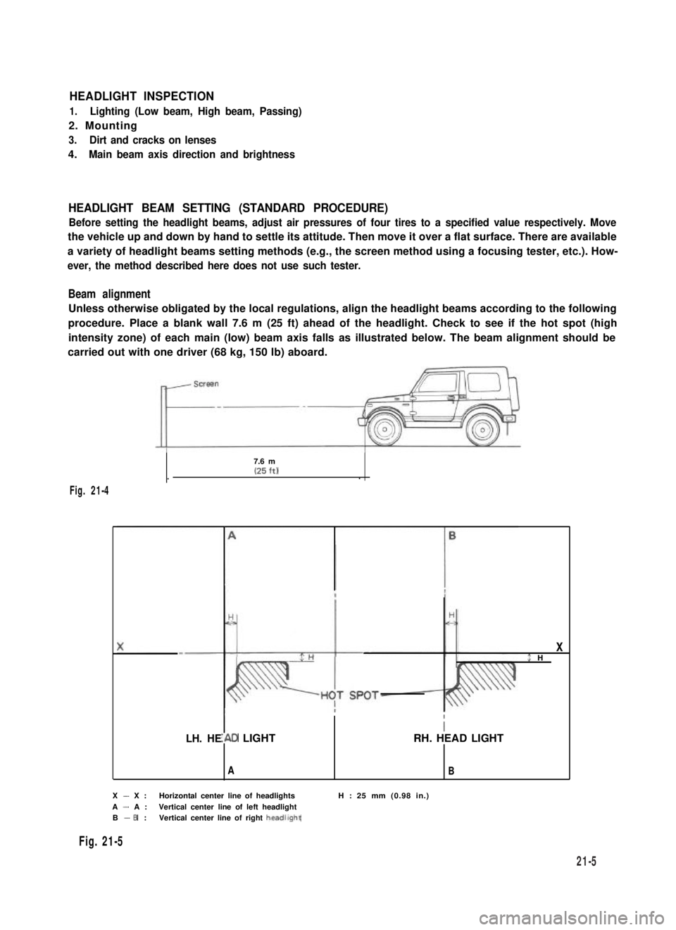
Beam alignment
Unless otherwise obligated by the local regulations, align the headlight beams according to the following
procedure. Place a blank wall 7.6 m (25 ft) ahead of the headlight. Check to see if the hot spot (high
intensity zone) of each main (low) beam axis falls as illustrated below. The beam alignment should be
carried out with one driver (68 kg, 150 lb) aboard.
7.6 m(25 ft)..
Fig. 21-4
LH. HE
X$ H
I
I\D LIGHTRH. HEAD LIGHT
AB
X - X :Horizontal center line of headlightsH : 25 mm (0.98 in.)
A - A :Vertical center line of left headlightB - 6 :Vertical center line of right headllght
Fig. 21-5
21-5
Page 453 of 962
MAINTENANCE
(1) Headlight adjustment
There are two screws (1)and (2)which can be
used for adjustment. Use these screws to
adjust the headlight position for the vertical
and horizontal alignment of each beam.
(2) Head light dimmer switch
Using circuit tester, check each circuit for
continuity by putting tester probe pins to
the terminals shown in Fig. 21-7. With switch
kept in LOW BEAM position, tester should
indicate continuity between terminals 0 and
@ . Similarly, there should be continuity
between terminals @ and @ when in HIGH
BEAM position.
Fig. 21-6
Switch connector
1”mmmm-J
1.Green/Red (Green/Black)8.Red2.Green/Yellow9.Blue/Green
3.Green10.Brown/Yellow
4.Yellow11.Red/Blue
5.White/Blue12.Red/Yellow
6.Yellow/Blue13.White7.Red/White
1 17 1 18 119 1
14.Yellow/White
15.Blue16.Blue/Red
Fig. 21-7
17.Blue/Black
18.Black19.Blue/White
Combination switch (Lighting switch circuit)
Fig. 27-8
II
II I, Brown(Yellow
21-6