Page 247 of 962

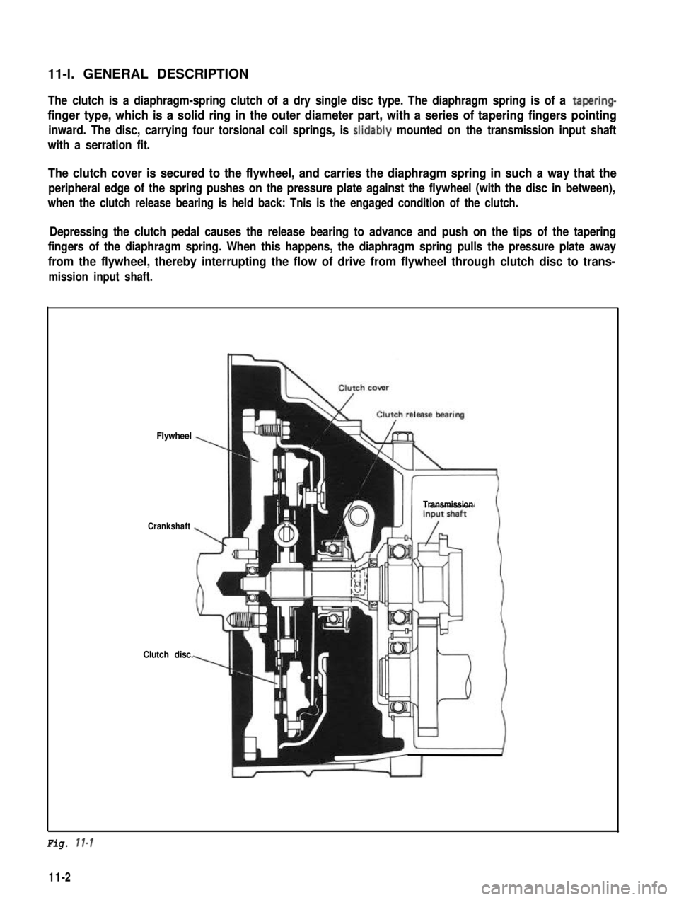
11-l. GENERAL DESCRIPTIONThe clutch is a diaphragm-spring clutch of a dry single disc type. The diaphragm spring is of a tapering-
finger type, which is a solid ring in the outer diameter part, with a series of tapering fingers pointing
inward. The disc, carrying four torsional coil springs, is slidably mounted on the transmission input shaft
with a serration fit.
The clutch cover is secured to the flywheel, and carries the diaphragm spring in such a way that the
peripheral edge of the spring pushes on the pressure plate against the flywheel (with the disc in between),
when the clutch release bearing is held back: Tnis is the engaged condition of the clutch.
Depressing the clutch pedal causes the release bearing to advance and push on the tips of the tapering
fingers of the diaphragm spring. When this happens, the diaphragm spring pulls the pressure plate away
from the flywheel, thereby interrupting the flow of drive from flywheel through clutch disc to trans-
mission input shaft.
Flywheel
Crankshaft
Clutch disc.
Transmission
Fig. 11-l
11-2
Page 289 of 962

14-1. GENERAL DESCRIPTION
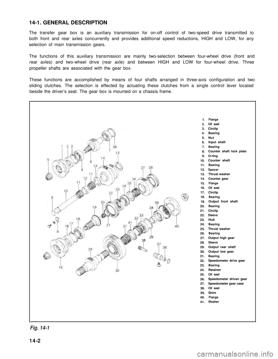
The transfer gear box is an auxiliary transmission for on-off control of two-speed drive transmitted to
both front and rear axles concurrently and provides additional speed reductions, HIGH and LOW, for any
selection of main transmission gears.
The functions of this auxiliary transmission are mainly two-selection between four-wheel drive (front and
rear axles) and two-wheel drive (rear axle) and between HIGH and LOW for four-wheel drive. Three
propeller shafts are associated with the gear box.
These functions are accomplished by means of four shafts arranged in three-axis configuration and two
sliding clutches. The selection is effected by actuating these clutches from a single control lever located
beside the driver’s seat. The gear box is mounted on a chassis frame.
1.Flange
2.Oil seal
3.Circlip
4.Bearing
5.Nut6.Input shaft
7.Bearing
8.Counter shaft lock plate
9.O-ring
10.Counter shaft
11.Bearing
12.Spacer
13.Thrust washer
14.Counter gear
15.Flange
16.Oil seal
17.Circlip
18.Bearing
19.Output front shaft
20.Bearing
21.Circlip
22.Sleeve
23.Hub
24.Bearing
25.Thrust washer
26.Bearing
27.Output high gear
28.Sleeve
29.Output rear shaft
30.Output low gear
31.Bearing
32.Speedometer drive gear
33.Bearing
34.Retainer
35.Oil seal
36.Speedometer driven gear
37.Speedometer gear case
38.Oil seal
39.Shim
40.Flange
41.Washer
Fig. 14- 1
14-2
Fig. 14-1
Page 312 of 962
151. GENERAL DESCRIPTION
These automobiles, covered in this manual are four-wheel drive machines and, as such, use three propeller
shafts designated as No. 1, No. 2 and No. 3.
No, 1 propeller shaft transmits drive from the transmission to the transfer gear box. No. 2 shaft and No. 3
shaft extend from the transfer gear box, the former driving the front axle and the latter the rear axle.
The cross spider in each universal joint is fitted with four needle roller bearings.
From
TQ transfer
transmission casaTo transfar casa
Propeller shaft No. 2
To rear differential
To front differential
To transfer case
15-2
Fig. 15-1
Page 411 of 962
4) Before installing brake drum, to maximize
brake shoe-todrum clearance, put screw
driver between rod and ratchet and push
down ratchet as shown in figure.
\
2. Ratchet
3. Driver
Below figure shows ratchet positionwhere brake shoe-to-drum clearanceis maximum.
Fig. 19-54
5) Install brake drum after making sure that
inside of brake drum and brake shoes are free
from dirt and oil.
6) Torque wheel nuts and brake drum nuts to
specification.
NOTE:
If brake backing plate was removed from wheel
cylinder or brake pipe was disconnected from
wheel cylinder. Bleed air from brake system.
(For bleeding operation, refer to p. 19-46.)
7) Upon completion of all jobs, depress brake
pedal with about 30 kg (66 Ibs) load four or
five times so as to obtain proper drum-to-
shoe clearance.
8) Check to ensure that brake drum is free from
dragging and proper braking is obtained. Then
remove car from hoist and perform brake test
(foot brake and parking brake).
Fig. 19-55
19-26