1987 SUZUKI GRAND VITARA boot
[x] Cancel search: bootPage 29 of 962
NOTE:
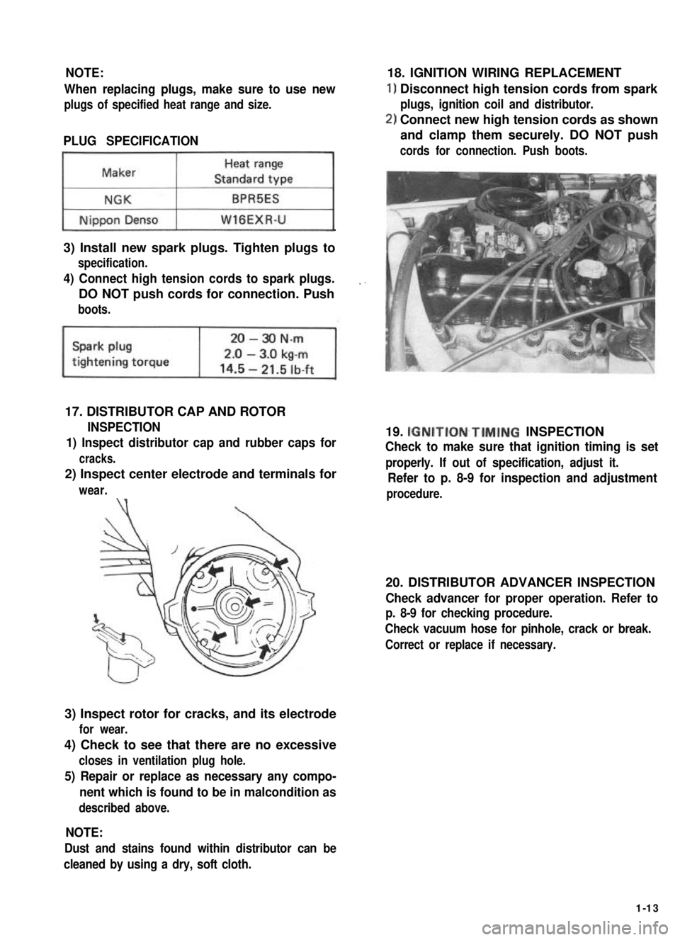
When replacing plugs, make sure to use new
plugs of specified heat range and size.
PLUG SPECIFICATION
~1
3) Install new spark plugs. Tighten plugs to
specification.
4) Connect high tension cords to spark plugs.
DO NOT push cords for connection. Push
boots.
17. DISTRIBUTOR CAP AND ROTOR
INSPECTION
1) Inspect distributor cap and rubber caps for
cracks.
2) Inspect center electrode and terminals for
wear.\‘(
3) Inspect rotor for cracks, and its electrode
for wear.
4) Check to see that there are no excessive
closes in ventilation plug hole.
5) Repair or replace as necessary any compo-
nent which is found to be in malcondition as
described above.
18. IGNITION WIRING REPLACEMENT
1) Disconnect high tension cords from spark
plugs, ignition coil and distributor.
2) Connect new high tension cords as shown
and clamp them securely. DO NOT push
cords for connection. Push boots.
19. IGNITION~TIMING INSPECTION
Check to make sure that ignition timing is set
properly. If out of specification, adjust it.
Refer to p. 8-9 for inspection and adjustment
procedure.
20. DISTRIBUTOR ADVANCER INSPECTION
Check advancer for proper operation. Refer to
p. 8-9 for checking procedure.
Check vacuum hose for pinhole, crack or break.
Correct or replace if necessary.
NOTE:
Dust and stains found within distributor can be
cleaned by using a dry, soft cloth.
1-13
Page 37 of 962
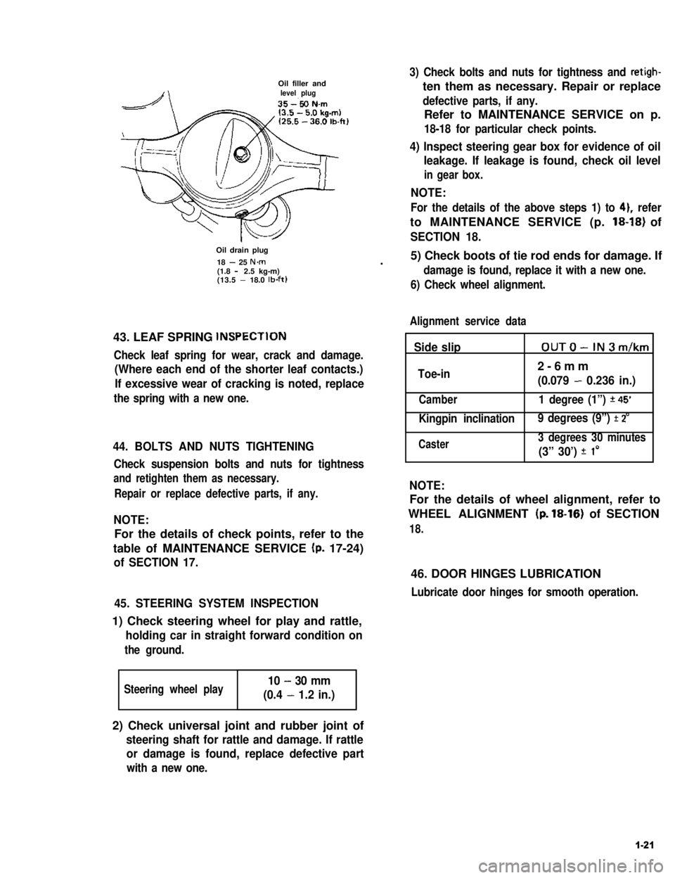
Oil filler andlevel plug
Oil drain plug
18 - 25 N.m(1.8 - 2.5 kg-m)(13.5 - 18.0 lb-ft)
43. LEAF SPRING lNSPECTlON
Check leaf spring for wear, crack and damage.
(Where each end of the shorter leaf contacts.)
If excessive wear of cracking is noted, replace
the spring with a new one.
44. BOLTS AND NUTS TIGHTENING
Check suspension bolts and nuts for tightness
and retighten them as necessary.
Repair or replace defective parts, if any.
NOTE:
For the details of check points, refer to the
table of MAINTENANCE SERVICE (p. 17-24)
of SECTION 17.
45. STEERING SYSTEM INSPECTION
1) Check steering wheel for play and rattle,
holding car in straight forward condition on
the ground.
Steering wheel play10 - 30 mm
(0.4 - 1.2 in.)
3) Check bolts and nuts for tightness and retigh-
ten them as necessary. Repair or replace
defective parts, if any.
Refer to MAINTENANCE SERVICE on p.
18-18 for particular check points.
4) Inspect steering gear box for evidence of oil
leakage. If leakage is found, check oil level
in gear box.
NOTE:
For the details of the above steps 1) to 41, refer
to MAINTENANCE SERVICE (p. 18-18) of
SECTION 18.
.5) Check boots of tie rod ends for damage. If
damage is found, replace it with a new one.
6) Check wheel alignment.
Alignment service data
Side slipOUTO-IN3m/km
Toe-in2-6mm
(0.079 - 0.236 in.)
Camber1 degree (1”) *45’
Kingpin inclination 9 degrees (9”) f 2’
Caster3 degrees 30 minutes
(3” 30’) f I0
NOTE:
For the details of wheel alignment, refer to
WHEEL ALIGNMENT (p. 18-16) of SECTION
18.
46. DOOR HINGES LUBRICATION
Lubricate door hinges for smooth operation.
2) Check universal joint and rubber joint of
steering shaft for rattle and damage. If rattle
or damage is found, replace defective part
with a new one.
1-21
Page 64 of 962
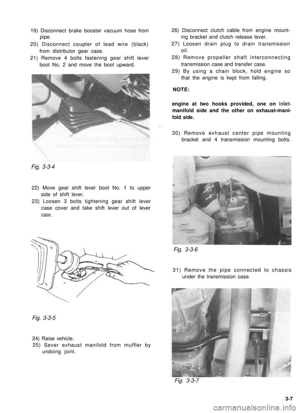
19) Disconnect brake booster vacuum hose from
pipe.
20) Disconnect coupler of lead wire (black) from distributor gear case.
21) Remove 4 bolts fastening gear shift lever boot No. 2 and move the boot upward.Fig. 3-3-4
22) Move gear shift lever boot No. 1 to upperside of shift lever.
23) Loosen 3 bolts tightening gear shift lever case cover and take shift lever out of lever
case.
26) Disconnect clutch cable from engine mount- ing bracket and clutch release lever.
27) Loosen drain plug to drain transmission oil.
28) Remove propeller shaft interconnecting transmission case and transfer case.
29) By using a chain block, hold engine so that the engine is kept from falling.
NOTE:
engine at two hooks provided, one on
inlet-
manifold side and the other on exhaust-mani-
fold side.
30) Remove exhaust center pipe mounting bracket and 4 transmission mounting bolts.
Fig. 3-3-6
31) Remove the pipe connected to chassis
under the transmission case.
Fig. 3-3-5
24) Raise vehicle.25) Sever exhaust manifold from muffler by undoing joint.
Fig. 3-3-7
3-7
Page 117 of 962
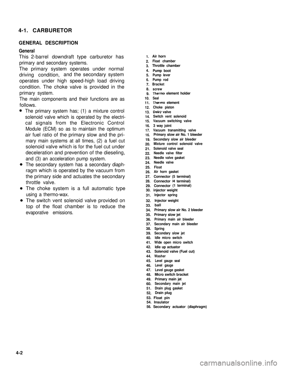
4-1. CARBURETOR
GENERAL DESCRIPTION
General
This 2-barrel downdraft type carburetor has
primary and secondary systems.
The primary system operates under normal
driving condition,and the secondary system
operates under high speed-high load driving
condition. The choke valve is provided in the
primary system.
The main components and their functions are as
follows.
The primary system has; (1) a mixture control
solenoid valve which is operated by the electri-
cal signals from the Electronic Control
Module (ECM) so as to maintain the optimum
air fuel ratio of the primary slow and the pri-
mary main systems at all times, (2) a fuel cut
solenoid valve which is for the fuel cut under
deceleration and prevention of the dieseling,
and (3) an acceleration pump system.
The secondary system has a secondary diaph-
ragm which is operated by the vacuum from
the primary side and actuates the secondary
throttle valve.
The choke system is a full automatic type
using a thermo-wax.
The switch vent solenoid valve provided on
top of the float chamber is to reduce the
evaporative emissions.
1.Air horn
2.Float chamber
3.Throttle chamber
4.Pump boot5.Pump lever
6.Pump rod
7.Bracket
8.screw
9.Therm0 element holder
10.Seal
11.Therm0 element
12.Choke piston
13.Delay valve
14.Switch vent solenoid
15.Vacuum switching valve
16.3 way joint
17.Vacuum transmitting valve
16.Primary slow air No. 1 bleeder
19.Secondary slow air bleeder
20.Mixture control solenoid valve
21.Solenoid valve seal
22.Needle valve filter
23.Needle valve gasket
24.Needle valve
25.Float
26.Air horn gasket
27.Connector (5 terminal)
28.Connector (4 terminal)
29.Connector (1 terminal)
30. injector weight
31.Injector spring
32.Injector weight
33.
34.Primary slow air No. 2 bleeder
35.Primary slow jet
36.Primary main air bleeder
37.Secondary main air bleeder
38.Spring
39.Secondary slow jet
40.Idle micro switch
41.Wide open micro switch
42.Idle up actuator43.Solenoid valve (Fuel cut)
44.Washer
45.Level gauge seal
46.Level gauge
47.Level gauge gasket
48.Micro switch bracket
49.Primary main jet
60.Secondary main jet
51.Drain plug gasket
52,Drain plug
53. Float pin54. Insulator56. Secondary actuator (diaphragm)
4-2
ball
Page 215 of 962
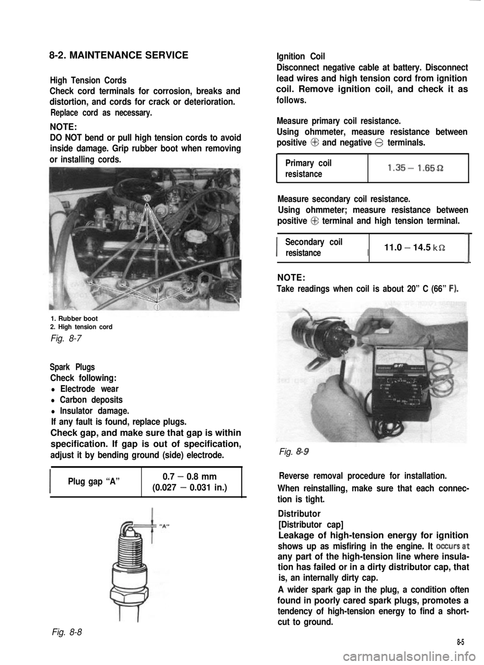
8-2. MAINTENANCE SERVICEIgnition Coil
High Tension Cords
Check cord terminals for corrosion, breaks and
distortion, and cords for crack or deterioration.
Replace cord as necessary.
NOTE:
DO NOT bend or pull high tension cords to avoid
inside damage. Grip rubber boot when removing
orinstalling cords.
1. Rubber boot2. High tension cord
Fig. 8-7
Spark Plugs
Check following:
l Electrode wear
l Carbon deposits
l Insulator damage.
If any fault is found, replace plugs.
Check gap, and make sure that gap is within
specification. If gap is out of specification,
adjust it by bending ground (side) electrode.
I
Plug gap “A”0.7 - 0.8 mm
(0.027 - 0.031 in.)
Disconnect negative cable at battery. Disconnect
lead wires and high tension cord from ignition
coil. Remove ignition coil, and check it as
follows.
Measure primary coil resistance.
Using ohmmeter, measure resistance between
positive @ and negative @ terminals.
Primary coil
resistance1.35- 1.65D
Measure secondary coil resistance.
Using ohmmeter; measure resistance between
positive @ terminal and high tension terminal.
I
Secondary coil
resistanceI11.0 - 14.5 kSZ
I
NOTE:
Take readings when coil is about 20” C (66” F).
Fig. &9
Reverse removal procedure for installation.
When reinstalling, make sure that each connec-
tion is tight.
Distributor
[Distributor cap]
Leakage of high-tension energy for ignition
shows up as misfiring in the engine. It occursat
any part of the high-tension line where insula-
tion has failed or in a dirty distributor cap, that
is, an internally dirty cap.
A wider spark gap in the plug, a condition often
found in poorly cared spark plugs, promotes a
tendency of high-tension energy to find a short-
cut to ground.
Fig. 8-8
8-5
Page 257 of 962
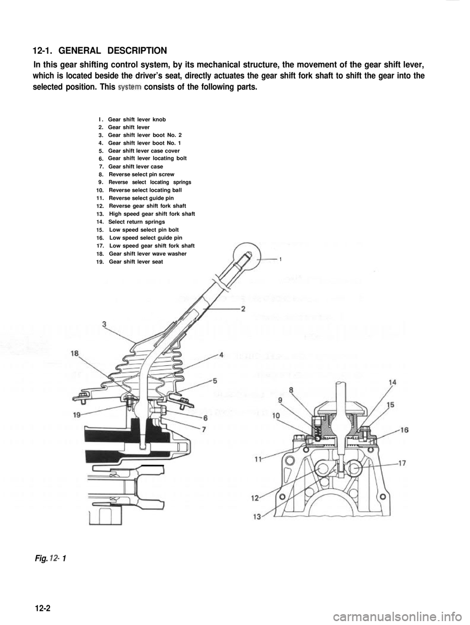
12-1. GENERAL DESCRIPTION
In this gear shifting control system, by its mechanical structure, the movement of the gear shift lever,
which is located beside the driver’s seat, directly actuates the gear shift fork shaft to shift the gear into the
selected position. This system consists of the following parts.
I.2.
3.4.
5.6.7.
8.9.
10.11.
12.
13.14.
15.
16.17.
18.
19.
Gear shift lever knobGear shift leverGear shift lever boot No. 2
Gear shift lever boot No. 1Gear shift lever case coverGear shift lever locating bolt
Gear shift lever caseReverse select pin screwReverse select locating springs
Reverse select locating ball
Reverse select guide pinReverse gear shift fork shaft
High speed gear shift fork shaft
Select return springs
Low speed select pin bolt
Low speed select guide pin
Low speed gear shift fork shaft
Gear shift lever wave washer
Gear shift lever seat1
Fig. 12- 1
12-2
Page 258 of 962
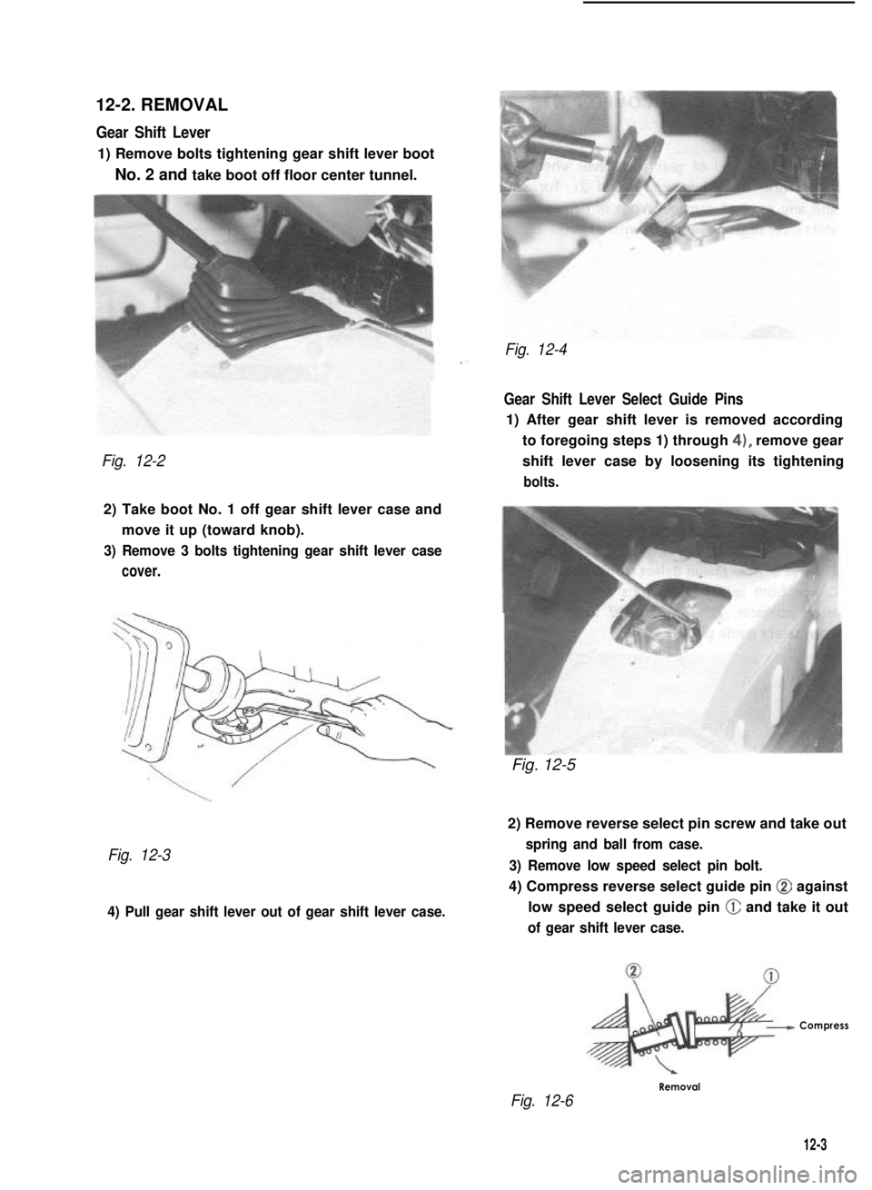
12-2. REMOVAL
Gear Shift Lever
1) Remove bolts tightening gear shift lever boot
No. 2 and take boot off floor center tunnel.
Fig. 12-2
2) Take boot No. 1 off gear shift lever case and
move it up (toward knob).
3) Remove 3 bolts tightening gear shift lever case
cover.
Fig. 12-3
4) Pull gear shift lever out of gear shift lever case.
Fig. 12-4
Gear Shift Lever Select Guide Pins
1) After gear shift lever is removed according
to foregoing steps 1) through 4), remove gear
shift lever case by loosening its tightening
bolts.
Fig. 12-5
2) Remove reverse select pin screw and take out
spring and ball from case.
3) Remove low speed select pin bolt.
4) Compress reverse select guide pin @ against
low speed select guide pin @ and take it out
of gear shift lever case.
Compress
Fig. 12-6
Removal
12-3
Page 261 of 962
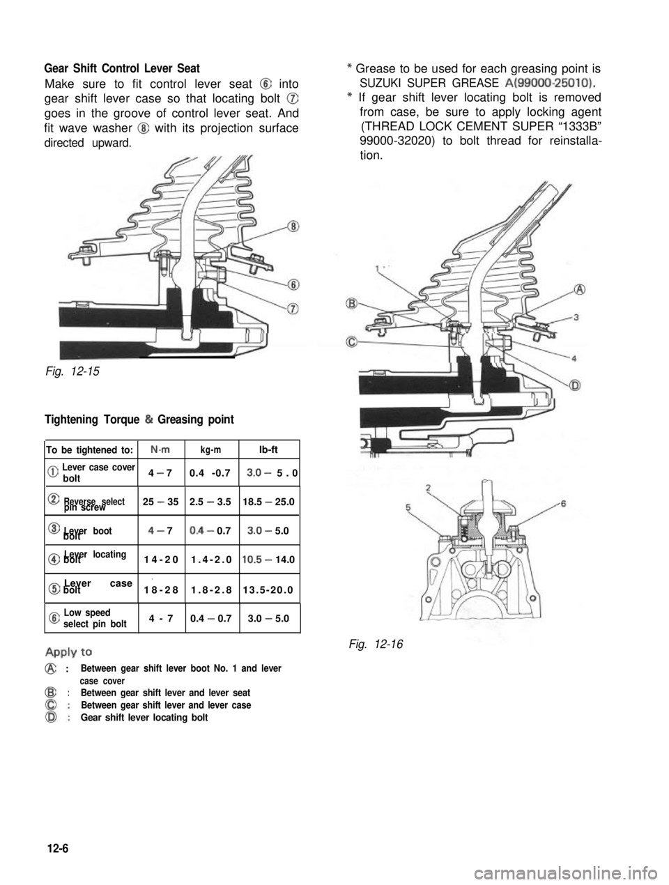
Gear Shift Control Lever Seat
Make sure to fit control lever seat @I into
gear shift lever case so that locating bolt @
goes in the groove of control lever seat. And
fit wave washer @J with its projection surface
directed upward.
--
Fig. 12-15
Tightening Torque (h Greasing point
To be tightened to:N-mkg-mlb-ft
(jj Lever case cover
bolt4 - 70.4 -0.73.0- 5.0
0Reverse selectpin screw25 - 352.5 - 3.518.5 - 25.0
0Lever bootbolt4- 70.4- 0.73.0- 5.0
@Lever locatingbolt14-201.4-2.010.5- 14.0
0Lever case ’bolt18-281.8-2.813.5-20.0
a Low speed
select pin bolt4-70.4 - 0.73.0 - 5.0
APPLY to
@ :Between gear shift lever boot No. 1 and lever
case cover
@:Between gear shift lever and lever seat
Between gear shift lever and lever case
Gear shift lever locating bolt
* Grease to be used for each greasing point is
SUZUKI SUPER GREASE A(99000-25010).
* If gear shift lever locating bolt is removed
from case, be sure to apply locking agent
(THREAD LOCK CEMENT SUPER “1333B”
99000-32020) to bolt thread for reinstalla-
tion.
Fig. 12-16
12-6