Page 409 of 962
6) Remove brake drum and check fan-shaped
ratchet position.
If it has shifted off its previous position in step
2) when it was pushed down, it proves proper
operation of shoe adjusting system.
PRECAUTIONS ON INSTALLATION
Wheel Cylinder
1) Tighten wheel cylinder to brake back plate to
specified torque.
2)Tighten flare nut of brake pipe to specified
torque.
3) Install breather plug cap.
8-12N.m14-18N.m-(0.8 - 1.2 kg-m)(I .41.8 kg-m)4,(6.0 - 8.5 lb-ft)(10.5-13.0 lb-ft)
1. Brake back plate3. Brake pipe
2. Brake pipe flare nut4. Wheel cylinder bolts
Fig. 19-50
Brake Shoes
1) Assemble parts as shown in the reverse order
of removal.
If not, replace strut assembly.
Fig. 19-49-4
NOTE:
For brake drum installation, refer to steps 1)
through 8) of brake drum installation in this
section (p. 19-25).
Fig. 19-50-1
NOTE:
When installing shoes, use care not to cause
damage to wheel cylinder boots.
19-24
Page 415 of 962
19-5. BRAKE BOOSTERDISASSEMBLY
REMOVAL
1) Take out fluid from master cylinder with a
syringe or such.
2) Disconnect 2 brake pipes from master cylinder
and remove master cylinder from booster.
3) Disconnect vacuum hose from booster.
4) Disconnect push rod clevis from brake pedal
arm.
5) Remove attaching nuts and then booster as
shown.
Vacuum hose
2.Booster3. Push rod clevis
4.Dash panel5.Attaching nuts6.Master cylinder
7.Gasket
8. Split pin
9. Master cylinder pin
10. Gasket11 Attaching nuts
Fig. 19-65
49
-@P
Iii
1. Vacuum check valve
2. Grommet3. Booster No. 1 body4. Piston rod
5. Reaction disc6. Booster piston return
spring7. Valve stopper key8. Booster piston9. Booster air valve assembly10. Pressure plate
Fig. 19-66
11.Diaphragm12.Booster No. 2body
13.No. 2 body oilseal14. Air cleaner separator15. Air cleaner element
16.Body bootNut
18.Bracket
19. Push rod clevis
1) Remove piston rod from booster.
2) Remove push rod clevis and nut.
Fig. 19-67
19-30
1.
17.
Page 416 of 962

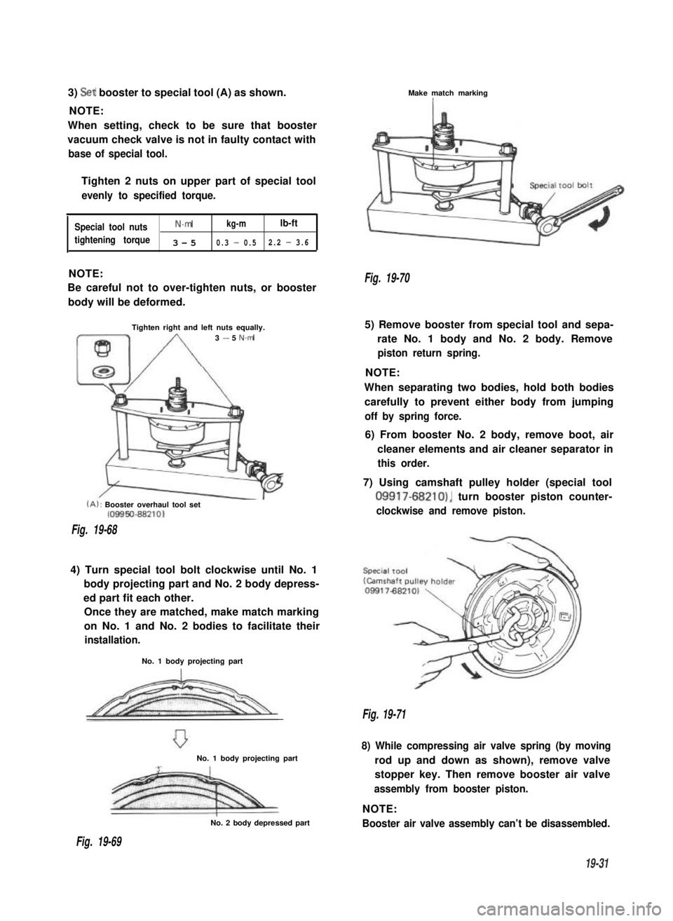
3) Set booster to special tool (A) as shown.
NOTE:
When setting, check to be sure that booster
vacuum check valve is not in faulty contact with
base of special tool.
Tighten 2 nuts on upper part of special tool
evenly to specified torque.
Special tool nutsN.mkg-mlb-ft
tightening torque3-50.3 - 0.52.2 - 3.6
NOTE:
Be careful not to over-tighten nuts, or booster
body will be deformed.
Tighten right and left nuts equally.3 - 5 N.m
(A): Booster overhaul tool set(09950-88210)
Fig. 19-68
4) Turn special tool bolt clockwise until No. 1
body projecting part and No. 2 body depress-
ed part fit each other.
Once they are matched, make match marking
on No. 1 and No. 2 bodies to facilitate their
installation.
No. 1 body projecting part
No. 1 body projecting part
No. 2 body depressed part
Make match markingI
Fig. 19-70
5) Remove booster from special tool and sepa-
rate No. 1 body and No. 2 body. Remove
piston return spring.
NOTE:
When separating two bodies, hold both bodies
carefully to prevent either body from jumping
off by spring force.
6) From booster No. 2 body, remove boot, air
cleaner elements and air cleaner separator in
this order.
7) Using camshaft pulley holder (special tool
09917-68210), turn booster piston counter-
clockwise and remove piston.
Fig. 19-71
8) While compressing air valve spring (by moving
rod up and down as shown), remove valve
stopper key. Then remove booster air valve
assembly from booster piston.
NOTE:
Booster air valve assembly can’t be disassembled.
Fig. 19-69
19-31
Page 419 of 962
BOOSTER INSPECTION TABLE
Part
1. Booster piston
2. Air valve ass’y
(Control valve spring)
3. Reaction disc
4. Diaphragm and boot
5. Piston rod
6. Booster No. 1 & No. 2
body.
7. Air filters and separator
Inspect ForCorrective Action
Cracks, distortion or damage.Replace.
Damaged or worn seal surfaces.Replace.
Damage or wear.Replace.
Damage.Replace.
Damage or bend.Replace.
1. Scratches, scores, pits, dents, orReplace, unless easily
other damage affecting rolling orrepaired.
sealing of diaphragm or other seals.
2. Cracks, damage at ears, damagedReplace, unless easily
threads on studs.repa i red.
3. Bent or nicked locking lugs.Replace, unless easily
repaired.
4. Loose studs.Replace.
Dirt.Replace.
Fig. 19-79
19-34
Page 421 of 962

2,
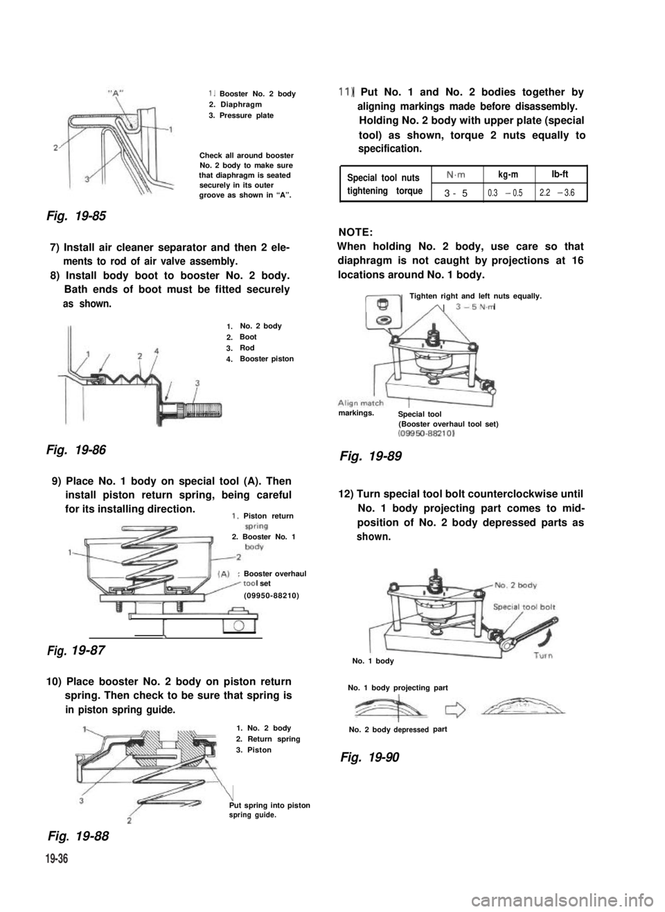
Fig. 19-85
1. Booster No. 2 body2. Diaphragm
3. Pressure plate
Check all around boosterNo. 2 body to make surethat diaphragm is seatedsecurely in its outergroove as shown in “A”.
7) Install air cleaner separator and then 2 ele-
ments to rod of air valve assembly.
8) Install body boot to booster No. 2 body.
Bath ends of boot must be fitted securely
as shown.
Fig. 19-86
1.No. 2 body
2.Boot
3.Rod
4.Booster piston
9) Place No. 1 body on special tool (A). Then
install piston return spring, being careful
for its installing direction.1. Piston return
Fig.
2. Booster No. 1
:Booster overhaultool set
(09950-88210)
1
I
19-87
10) Place booster No. 2 body on piston return
spring. Then check to be sure that spring is
in piston spring guide.
Fig.. 19-88
1. No. 2 body
2. Return spring
3. Piston
\Put spring into pistonspring guide.
11) Put No. 1 and No. 2 bodies together by
aligning markings made before disassembly.
Holding No. 2 body with upper plate (special
tool) as shown, torque 2 nuts equally to
specification.
Special tool nutsN.mkg-mlb-ft
tightening torque3-50.3 - 0.52.2 - 3.6
NOTE:
When holding No. 2 body, use care so that
diaphragm is not caught by projections at 16
locations around No. 1 body.
ml
Tighten right and left nuts equally.
A 3-5N.m
markings.Special tool(Booster overhaul tool set)(08850-88210)
Fig. 19-89
12) Turn special tool bolt counterclockwise until
No. 1 body projecting part comes to mid-
position of No. 2 body depressed parts as
shown.
No. 1 body
No. 1 body projecting part
No. 2 bodydepressedpart
Fig. 19-90
19-36
Page:
< prev 1-8 9-16 17-24