1987 SUZUKI GRAND VITARA cooling
[x] Cancel search: coolingPage 2 of 962
TABLE OF CONTENTS
GENERAL, SPECIAL TOOLS AND SERVICE MATERIALS
PERIODIC MAINTENANCE SERVICE
TROUBLE SHOOTING
ENGINE
FUEL SYSTEM (CARBURETOR, AIR CLEANER FUEL PUMP AND FUEL FILTER)
EMISSION CONTROL SYSTEM
ENGINE COOLING SYSTEM
CAR HEATER
IGNITION SYSTEM
CRANKING SYSTEM
CHARGING SYSTEM
CLUTCH
GEAR SHIFTING CONTROL
TRANSMISSION
TRANSFER GEAR BOX
PROPELLER SHAFTS
DIFFERENTIAL
SUSPENSION
STEERING SYSTEM
BRAKES
BODY SERVICE
,i BODY ELECTRICAL EQUIPMENT
SERVICE DATA
0
1
2
5
6
7
8
9
10
1111
12
13
14
15
16
17
18
19
20
21
22
4
3
SECTION
Page 21 of 962
![SUZUKI GRAND VITARA 1987 Service Repair Manual 1-2. ENGINE AND EMISSION CONTROL
1. WATER PUMP BELT INSPECTION
AND REPLACEMENT
[INSPECTION]
1) Disconnect negative battery lead at battery.
2) Inspect belt for cracks, cuts, deformation,
wear and clea SUZUKI GRAND VITARA 1987 Service Repair Manual 1-2. ENGINE AND EMISSION CONTROL
1. WATER PUMP BELT INSPECTION
AND REPLACEMENT
[INSPECTION]
1) Disconnect negative battery lead at battery.
2) Inspect belt for cracks, cuts, deformation,
wear and clea](/manual-img/20/57437/w960_57437-20.png)
1-2. ENGINE AND EMISSION CONTROL
1. WATER PUMP BELT INSPECTION
AND REPLACEMENT
[INSPECTION]
1) Disconnect negative battery lead at battery.
2) Inspect belt for cracks, cuts, deformation,
wear and cleanliness. If any defect, replace.
Check belt for tension. The belt is in’ proper
tension if it deflects 6 to 9 mm (0.24 - 0.35
in.) under thumb pressure (about 10 kg or
22 lb.)..
Belt tension6 - 9 mm (0.24 - 0.35 in.)
specificationas deflection
pulley
3) If the belt is too tight or too loose, adjust it
to specification by adjusting alternator
position.
4) Tighten alternator adjusting bolt and pivot
bolts.
5) Connect negative battery lead to battery.
[REPLACEMENT]
1) Disconnect negative battery lead at battery.
2) Loosen alternator adjusting bolt and pivot
bolts.
3) Replace water pump belt.
4) Adjust belt tension to specification and
tighten alternator adjusting bolt and pivot
bolts.
5) Connect negative battery lead to battery.
2. CAMSHAFT TIMING BELT INSPECTION
1) Disconnect negative battery lead at battery.
2) Loosen fan drive belt, and remove 4 bolts
securing radiator shroud panel and 4 nuts
securing engine cooling fan & clutch. Then
remove radiator shroud and cooling fan &
clutch at the same time.
3) Remove water pump belt and pump pulley.
4) Remove crankshaft pulley by removing 4
pulley bolts. The crankshaft timing belt
pulley bolt at the center need not be loosen-
ed.2 1
‘31. Key
2. Crankshaft pulley
3. Pulley bolt
1-5
Page 22 of 962
5) Remove timing belt outside cover. Inspect
the belt for damage or wear. When any
damage or wear is found on the belt, replace
it.
If belt replacement is necessary, be sure to
install the belt properly.
6) Remove cylinder head cover and loosen all
valve adjusting screws all the way to permit
free rotation of camshaft.
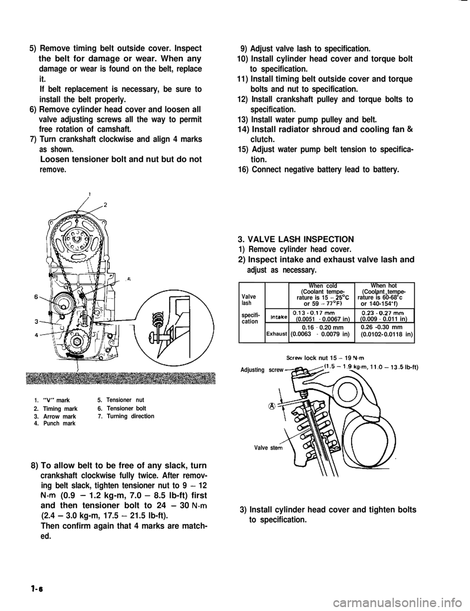
7) Turn crankshaft clockwise and align 4 marks
as shown.
Loosen tensioner bolt and nut but do not
remove.
9) Adjust valve lash to specification.
10) Install cylinder head cover and torque bolt
to specification.
11) Install timing belt outside cover and torque
bolts and nut to specification.
12) Install crankshaft pulley and torque bolts to
specification.
13) Install water pump pulley and belt.
14) Install radiator shroud and cooling fan &
clutch.
15) Adjust water pump belt tension to specifica-
tion.
16) Connect negative battery lead to battery.
3. VALVE LASH INSPECTION
1) Remove cylinder head cover.
2) Inspect intake and exhaust valve lash and
adjust as necessary.
1.“V” mark5.Tensioner nut
2.Timing mark6.Tensioner bolt
3.Arrow mark7.Turning direction4.Punch mark
8) To allow belt to be free of any slack, turn
crankshaft clockwise fully twice. After remov-
ing belt slack, tighten tensioner nut to 9 - 12
N-m (0.9- 1.2 kg-m, 7.0 - 8.5 lb-ft) first
and then tensioner bolt to 24 - 30 N-m
(2.4 - 3.0 kg-m, 17.5 - 21.5 lb-ft).
Then confirm again that 4 marks are match-
ed.
Valvelash specifi-cation
When coldWhen hot(Coolant tempe-(Coolant tempe---rature is 15 - 25’Crature is 60-68 c or 59 - or 140-154 f)
0.13-0.17mm 0.23-0.27mmIntake(0.0051- 0.0067 in)(0.009 - 0.011 in)
0.16-0.20 mm0.26 -0.30 mm(0.0102- Exhaust (0.0063 - 0.0079 in) 0.0118 in)
Screw lock nut 15 - 19 N.m
Adjusting screw
Valve ste
.5 lb-ft)
3) Install cylinder head cover and tighten bolts
to specification.
l-6
Page 23 of 962
NOTE:
Steps 1) - 6) outlined above must be performed
with ENGINE NOT RUNNING. For step 7),
be sure to have adequate ventilation while
engine is running
It is recommended to use engine oil of SE or
SF class.
NOTE:For temperatures below
32”F(O”C), it is highly
recommended to use SAE 5W-30 oil.
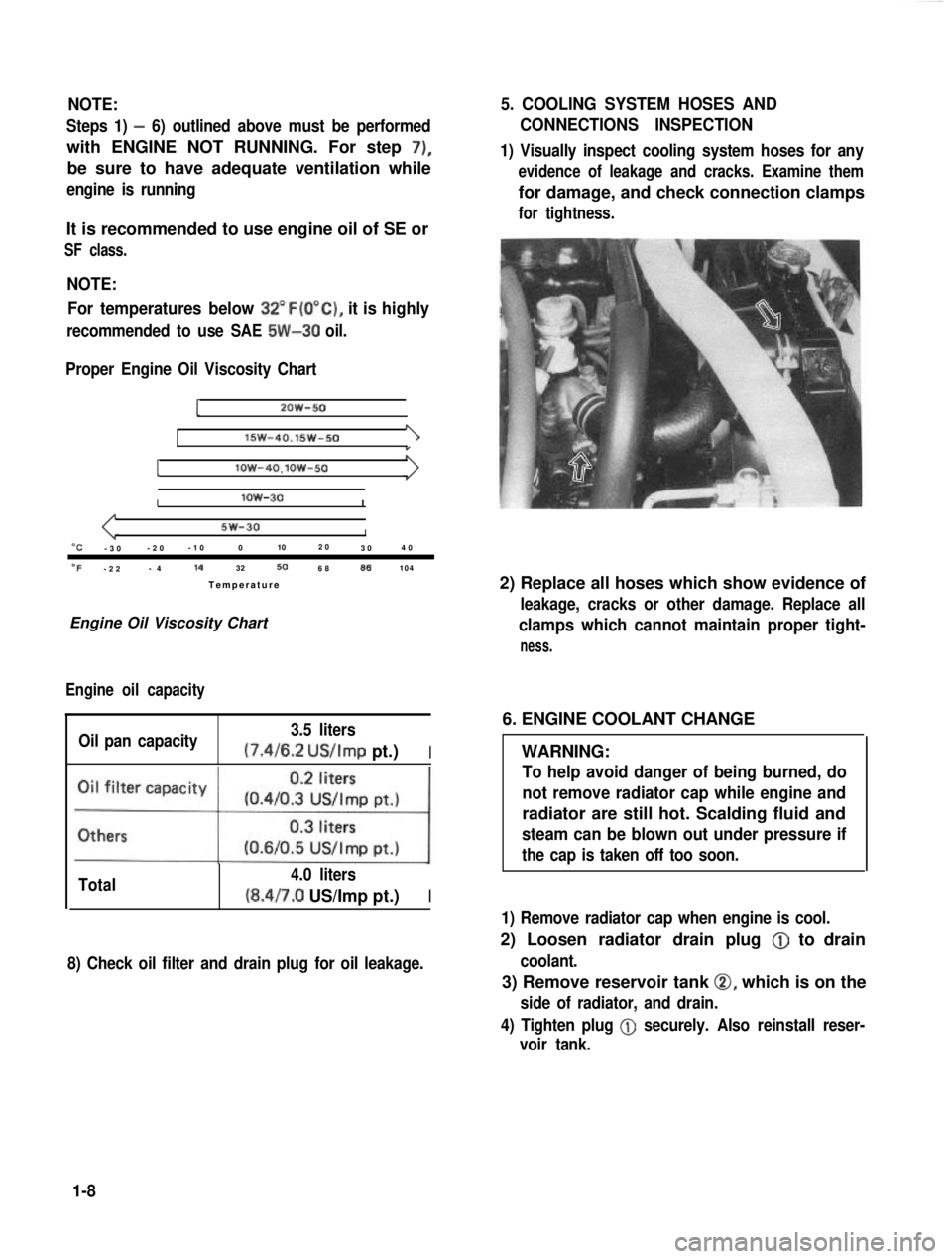
Proper Engine Oil Viscosity Chart
12OW-50
lSW-40.15w-501
Ilow-4O.lOW-50
Ilow-30I
5w-30I“C-3 0 -2
0 -1
0 0 102
0
30 4
0
OF-2 2 -
4 14
32506886104
Temperatur e
Engine Oil Viscosity Chart
Engine oil capacity
Oil pan capacity 3.5 liters (7.4/6.2
US/Imp pt.)I
Total 4.0 liters(8.4/7.0 US/Imp pt.)I
8) Check oil filter and drain plug for oil leakage.
5. COOLING SYSTEM HOSES AND
CONNECTIONS INSPECTION
1) Visually inspect cooling system hoses for any
evidence of leakage and cracks. Examine them
for damage, and check connection clamps
for tightness.
2) Replace all hoses which show evidence of
leakage, cracks or other damage. Replace all
clamps which cannot maintain proper tight-
ness.
6. ENGINE COOLANT CHANGE
WARNING:
To help avoid danger of being burned, do
not remove radiator cap while engine and
radiator are still hot. Scalding fluid and
steam can be blown out under pressure if
the cap is taken off too soon.
1) Remove radiator cap when engine is cool.
2) Loosen radiator drain plug @
to drain
coolant.
3) Remove reservoir tank 0, which is on the
side of radiator, and drain.
4) Tighten plug
@ securely. Also reinstall reser-
voir tank.
1-8
Page 25 of 962
CAUTION:
When changing engine coolant, use mixture
of 56% water and 50% GOLDEN CRUISER
1200for the market where ambient tem-
perature falls lower than -16°C (3°F) in
winter and mixture of 70% water and
30% GOLDEN CRUISER 1200for the
market where ambient temperature doesn’t
fall lower than -16°C (3” F).
Even in a market where no freezing tempe-
rature is anticipated, mixture of 70% water
and 30% GOLDEN CRUISER 1200
should be used for the purpose of corro-
sion protection and lubrication.
7. EXHAUST PIPES AND MOUNTINGS
INSPECTION
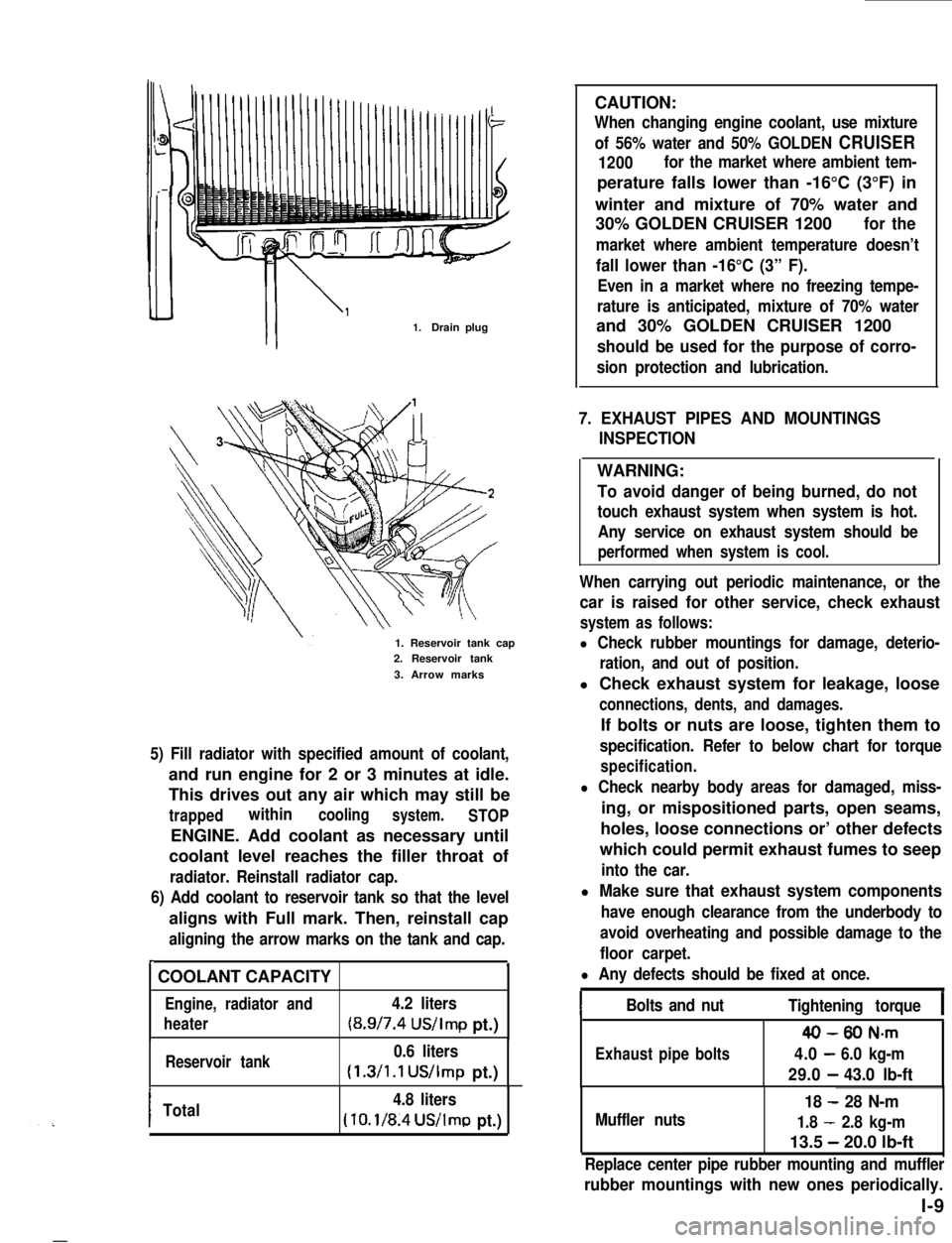
1.Drain plug
1. Reservoir tank cap2. Reservoir tank
3. Arrow marks
5) Fill radiator with specified amount of coolant,
and run engine for 2 or 3 minutes at idle.
This drives out any air which may still be
trappedwithincoolingsystem.STOP
ENGINE. Add coolant as necessary until
coolant level reaches the filler throat of
radiator. Reinstall radiator cap.
6) Add coolant to reservoir tank so that the level
aligns with Full mark. Then, reinstall cap
aligning the arrow marks on the tank and cap.
r.
COOLANT CAPACITY
Engine, radiator and4.2 liters
heater(8.9/7.4 US/Imp pt.)
Reservoir tank0.6 liters
(1.3/1.1 US/Imp pt.)
ITotal4.8 liters
(10.1/8.4US/lmp pt.)
WARNING:
To avoid danger of being burned, do not
touch exhaust system when system is hot.
Any service on exhaust system should be
performed when system is cool.
When carrying out periodic maintenance, or the
car is raised for other service, check exhaust
system as follows:
l Check rubber mountings for damage, deterio-
ration, and out of position.
l Check exhaust system for leakage, loose
connections, dents, and damages.
If bolts or nuts are loose, tighten them to
specification. Refer to below chart for torque
specification.
l Check nearby body areas for damaged, miss-
ing, or mispositioned parts, open seams,
holes, loose connections or’ other defects
which could permit exhaust fumes to seep
into the car.
l Make sure that exhaust system components
have enough clearance from the underbody to
avoid overheating and possible damage to the
floor carpet.
l Any defects should be fixed at once.
IBolts and nutTightening torqueI
40-80 N-m
Exhaustpipebolts4.0-6.0 kg-m
29.0-43.0 lb-ft
Muffler nuts
18 - 28 N-m
1.8 - 2.8 kg-m
13.5 - 20.0 lb-ft
Replace center pipe rubber mounting and muffler
rubber mountings with new ones periodically.
l-9
Page 32 of 962
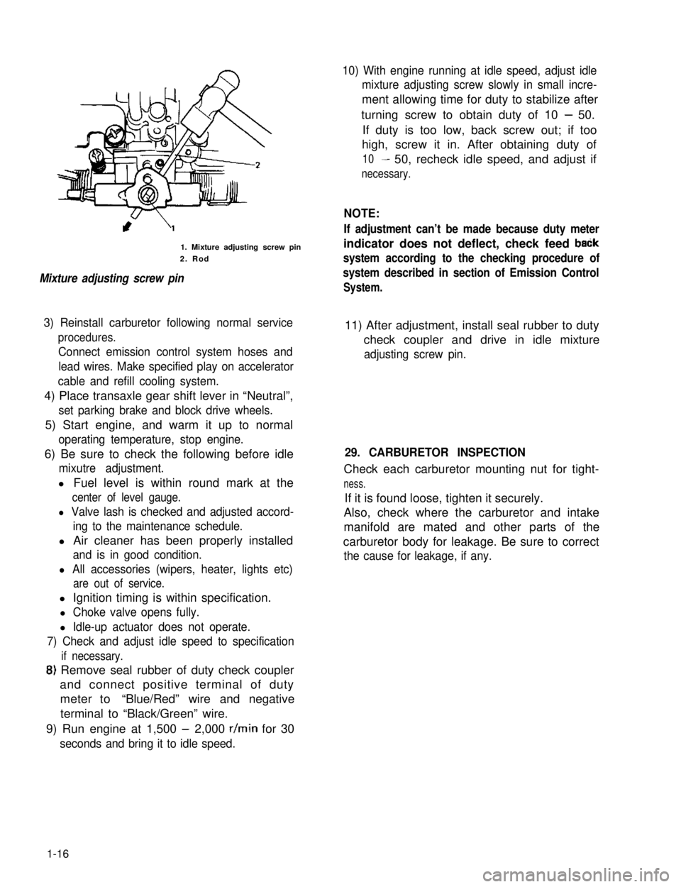
1. Mixture adjusting screw pin
2. Rod
Mixture adjusting screw pin
10) With engine running at idle speed, adjust idle
mixture adjusting screw slowly in small incre-
ment allowing time for duty to stabilize after
turning screw to obtain duty of 10 - 50.
If duty is too low, back screw out; if too
high, screw it in. After obtaining duty of
10- 50, recheck idle speed, and adjust if
necessary.
NOTE:
If adjustment can’t be made because duty meter
indicator does not deflect, check feed baCk
system according to the checking procedure of
system described in section of Emission Control
System.
3) Reinstall carburetor following normal service
procedures.
Connect emission control system hoses and
lead wires. Make specified play on accelerator
cable and refill cooling system.
11) After adjustment, install seal rubber to duty
check coupler and drive in idle mixture
adjusting screw pin.
4) Place transaxle gear shift lever in “Neutral”,
set parking brake and block drive wheels.
5) Start engine, and warm it up to normal
operating temperature, stop engine.
6) Be sure to check the following before idle
mixutre adjustment.
l Fuel level is within round mark at the
center of level gauge.
l Valve lash is checked and adjusted accord-
ing to the maintenance schedule.
l Air cleaner has been properly installed
and is in good condition.
l All accessories (wipers, heater, lights etc)
are out of service.
29. CARBURETOR INSPECTION
Check each carburetor mounting nut for tight-
ness.
If it is found loose, tighten it securely.
Also, check where the carburetor and intake
manifold are mated and other parts of the
carburetor body for leakage. Be sure to correct
the cause for leakage, if any.
l Ignition timing is within specification.
l Choke valve opens fully.
l Idle-up actuator does not operate.
7) Check and adjust idle speed to specification
if necessary.
8) Remove seal rubber of duty check coupler
and connect positive terminal of duty
meter to“Blue/Red” wire and negative
terminal to “Black/Green” wire.
9) Run engine at 1,500 - 2,000 r/min for 30
seconds and bring it to idle speed.
1-16
Page 45 of 962
9
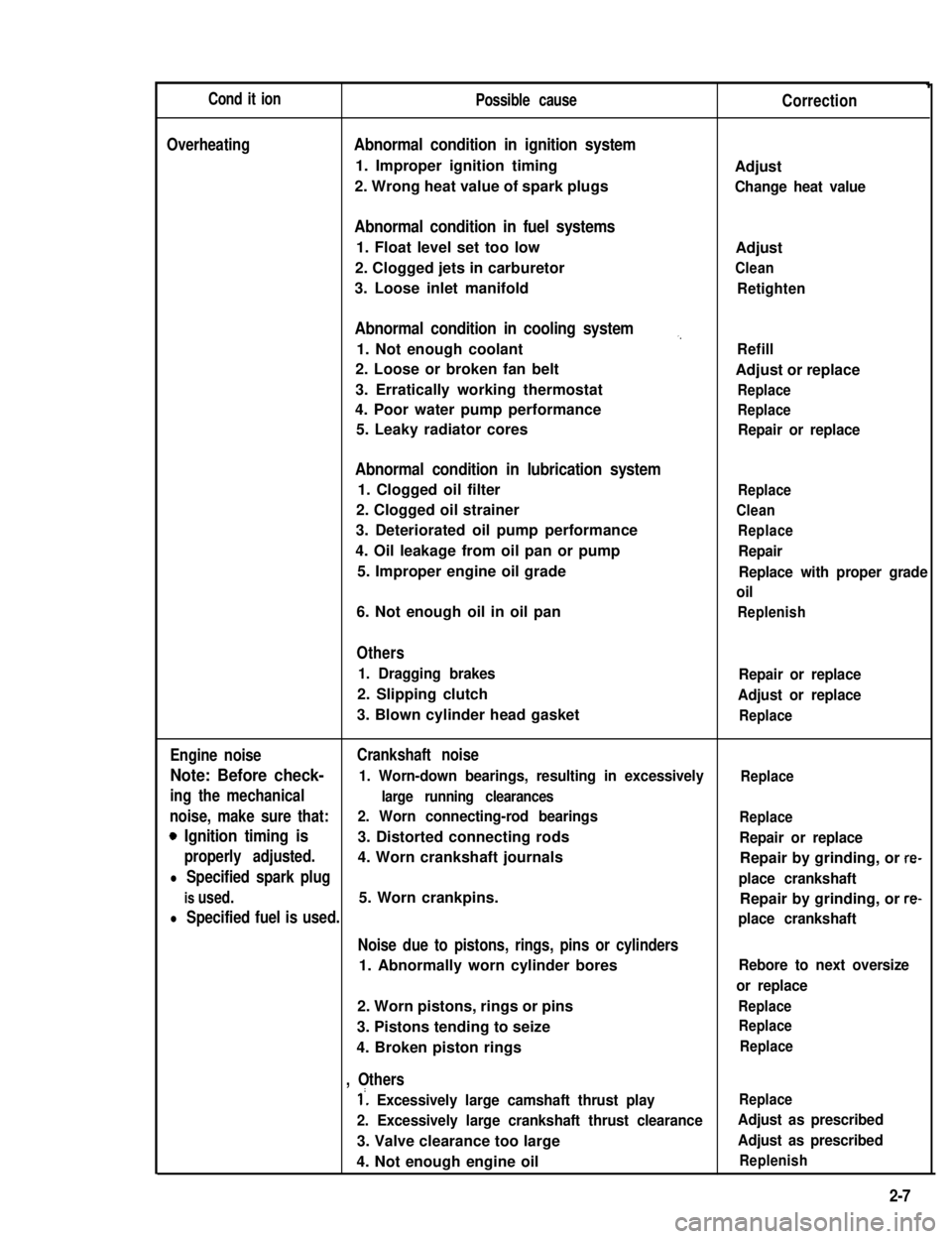
Cond it ionPossible causeCorrection
OverheatingAbnormal condition in ignition system
1. Improper ignition timingAdjust
2. Wrong heat value of spark plugsChange heat value
Abnormal condition in fuel systems
1. Float level set too lowAdjust
2. Clogged jets in carburetorClean
3. Loose inlet manifoldRetighten
Abnormal condition in cooling system,,
1. Not enough coolantRefill
2. Loose or broken fan beltAdjust or replace
3. Erratically working thermostatReplace
4. Poor water pump performanceReplace
5. Leaky radiator coresRepair or replace
Abnormal condition in lubrication system
1. Clogged oil filterReplace
2. Clogged oil strainerClean
3. Deteriorated oil pump performanceReplace
4. Oil leakage from oil pan or pumpRepair
5. Improper engine oil gradeReplace with proper grade
oil
6. Not enough oil in oil panReplenish
Others
1. Dragging brakesRepair or replace
2. Slipping clutchAdjust or replace
3. Blown cylinder head gasketReplace
Engine noiseCrankshaft noise
Note: Before check- 1. Worn-down bearings, resulting in excessivelyReplace
ing the mechanicallarge running clearances
noise, make sure that:2. Worn connecting-rod bearingsReplace
0 Ignition timing is3. Distorted connecting rodsRepair or replace
properly adjusted.4. Worn crankshaft journalsRepair by grinding, or re-
l Specified spark plugplace crankshaft
is used.5. Worn crankpins.Repair by grinding, or re-
l Specified fuel is used.place crankshaft
Noise due to pistons, rings, pins or cylinders
1. Abnormally worn cylinder boresRebore to next oversize
or replace
2. Worn pistons, rings or pinsReplace
3. Pistons tending to seizeReplace
4. Broken piston ringsReplace
, Others
1’. Excessively large camshaft thrust playReplace
2. Excessively large crankshaft thrust clearanceAdjust as prescribed
3. Valve clearance too largeAdjust as prescribed
4. Not enough engine oilReplenish
2-7
Page 62 of 962
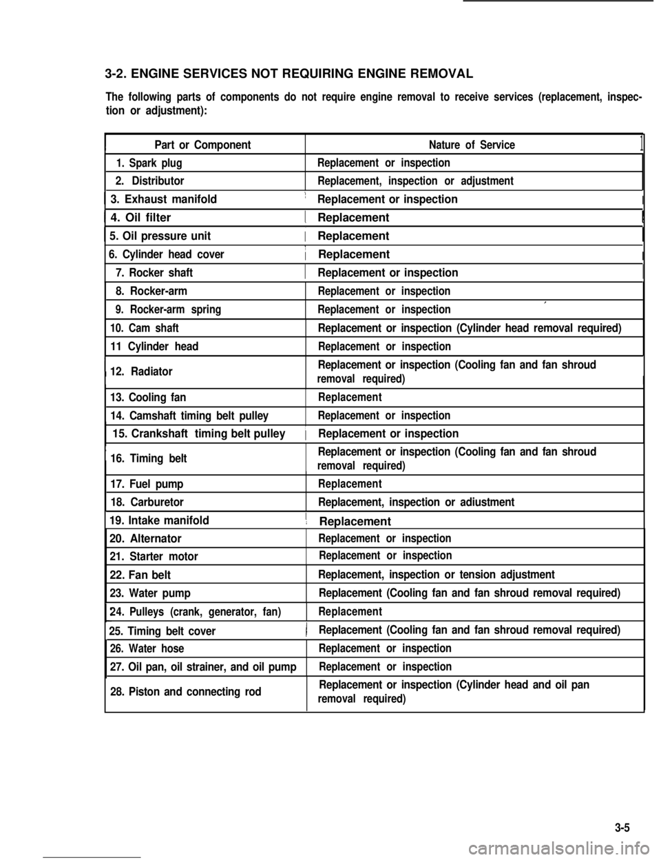
3-2. ENGINE SERVICES NOT REQUIRING ENGINE REMOVAL
The following parts of components do not require engine removal to receive services (replacement, inspec-
tion or adjustment):
Part or ComponentNature of Service1
1. Spark plug
2. Distributor
Replacement or inspection
Replacement, inspection or adjustment
1 3. Exhaust manifold1 Replacement or inspectionI
I 4. Oil filter1 ReplacementI
1 5. Oil pressure unit( Replacement
6. Cylinder head cover1 ReplacementI
I7. Rocker shaft1 Replacement or inspectionI
8. Rocker-arm
9. Rocker-arm spring
Replacement or inspection
Replacement or inspectionI
10. Cam shaft
11 Cylinder head
I12. Radiator
Replacement or inspection (Cylinder head removal required)
Replacement or inspection
Replacement or inspection (Cooling fan and fan shroud
removal required)I
13. Cooling fan
14. Camshaft timing belt pulley
Replacement
Replacement or inspection
I
15. Crankshaft timing belt pulley
16. Timing beltReplacement or inspection (Cooling fan and fan shroud
1 Replacement or inspection
removal required)
17. Fuel pump
18. Carburetor
Replacement
Replacement, inspection or adiustment
19. Intake manifold1 ReplacementI
20. Alternator
21. Starter motor
Replacement or inspection
22. Fan belt
23. Water pump
Replacement, inspection or tension adjustment
Replacement (Cooling fan and fan shroud removal required)
24.Pulleys (crank, generator, fan)Replacement
25. Timing belt cover)Replacement (Cooling fan and fan shroud removal required)
26. Water hose
27. Oil pan, oil strainer, and oil pump
Replacement or inspection
Replacement or inspection
28. Piston and connecting rodReplacement or inspection (Cylinder head and oil pan
removal required)
Replacement or inspection
3-5