1987 SUZUKI GRAND VITARA spark plugs
[x] Cancel search: spark plugsPage 28 of 962
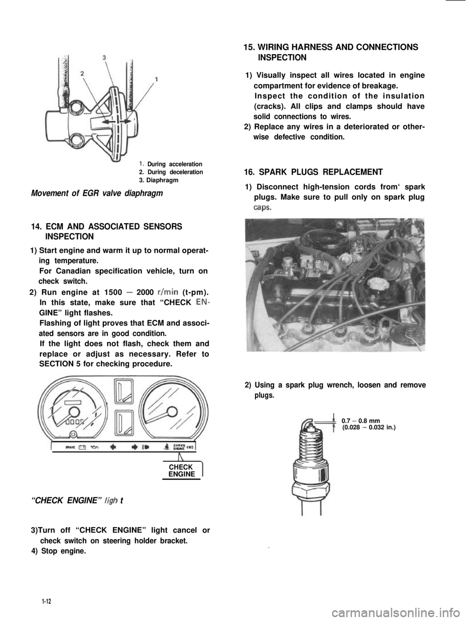
1. During acceleration
2. During deceleration
3. Diaphragm
Movement of EGR valve diaphragm
14. ECM AND ASSOCIATED SENSORS
INSPECTION
1) Start engine and warm it up to normal operat-
ing temperature.
For Canadian specification vehicle, turn on
check switch.
2) Run engine at 1500 - 2000 r/min (t-pm).
In this state, make sure that “CHECK EON-
GINE” light flashes.
Flashing of light proves that ECM and associ-
ated sensors are in good condition.
If the light does not flash, check them and
replace or adjust as necessary. Refer to
SECTION 5 for checking procedure.
A
CHECKENGINE
“CHECK ENGINE” ligh t
3)Turn off “CHECK ENGINE” light cancel or
check switch on steering holder bracket.
4) Stop engine.
15. WIRING HARNESS AND CONNECTIONS
INSPECTION
1) Visually inspect all wires located in engine
compartment for evidence of breakage.
Inspect the condition of the insulation
(cracks). All clips and clamps should have
solid connections to wires.
2) Replace any wires in a deteriorated or other-
wise defective condition.
16. SPARK PLUGS REPLACEMENT
1) Disconnect high-tension cords from‘ spark
plugs. Make sure to pull only on spark plug
caps.
2) Using a spark plug wrench, loosen and remove
plugs.
0.7 - 0.8 mm(0.028 - 0.032 in.)
1-12
Page 29 of 962
NOTE:
When replacing plugs, make sure to use new
plugs of specified heat range and size.
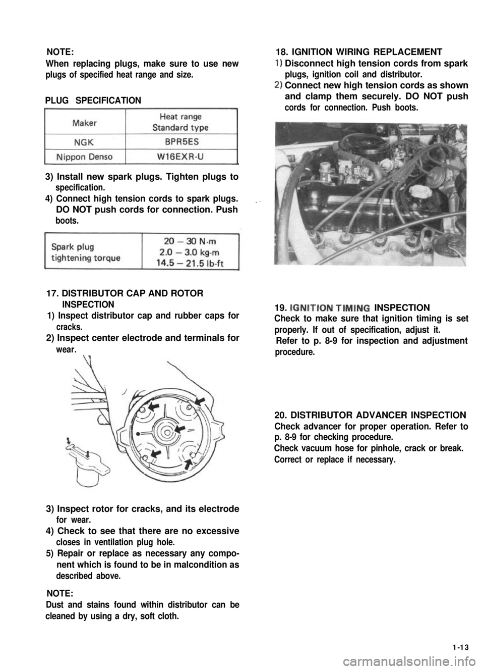
PLUG SPECIFICATION
~1
3) Install new spark plugs. Tighten plugs to
specification.
4) Connect high tension cords to spark plugs.
DO NOT push cords for connection. Push
boots.
17. DISTRIBUTOR CAP AND ROTOR
INSPECTION
1) Inspect distributor cap and rubber caps for
cracks.
2) Inspect center electrode and terminals for
wear.\‘(
3) Inspect rotor for cracks, and its electrode
for wear.
4) Check to see that there are no excessive
closes in ventilation plug hole.
5) Repair or replace as necessary any compo-
nent which is found to be in malcondition as
described above.
18. IGNITION WIRING REPLACEMENT
1) Disconnect high tension cords from spark
plugs, ignition coil and distributor.
2) Connect new high tension cords as shown
and clamp them securely. DO NOT push
cords for connection. Push boots.
19. IGNITION~TIMING INSPECTION
Check to make sure that ignition timing is set
properly. If out of specification, adjust it.
Refer to p. 8-9 for inspection and adjustment
procedure.
20. DISTRIBUTOR ADVANCER INSPECTION
Check advancer for proper operation. Refer to
p. 8-9 for checking procedure.
Check vacuum hose for pinhole, crack or break.
Correct or replace if necessary.
NOTE:
Dust and stains found within distributor can be
cleaned by using a dry, soft cloth.
1-13
Page 44 of 962

ConditionPossible causeCorrection
Erratic idling
(Improper engine
idling)
Abnormal condition in fuel system
1. Clogged carburetor jets
2. Incorrect idle adjustment
3. Clogged air cleaner element
4. Leaky manifold, carburetor or cylinder
head gaskets
5. Improper float level
6. Malfunctioning choke system
7. Malfunctioning fuel cut solenoid valve
Clean
Adjust
Clean or replace
Replace
Adjust
Adjust or replace
Replace
Others
1. Loose connection or disconnection. of
vacuum hoses
Connect
2. Malfunctioning PCV valve
3. Low compression
4. Loose carburetor and intake manifold bolts
and nuts
Check and replace as
necessary
Previously outlined
Tighten bolts and nuts
5. Leaky carburetor and intake manifold
gaskets
Replace
Abnormal detonationAbnormal condition in ignition system
1. Spark plugs tending to overheatChange plug heat value
2. Improper ignition timingAdjust
3. Loose connection in high-tension or low-Retighten
tension circuit.
Abnormal condition in fuel system
1. Clogged fuel filter and fuel lines
2. Clogged carburetor jets
3. Improper adjustment of float level
4. Malfunctioning fuel pump
5. Air inhaling from intake manifold and
carburetor gaskets
Replace or clean
Clean
Adjust
Replace
Replace
Abnormal condition in engine
1. Excessive carbon deposit on piston crowns
or cylinder head
Clean
2. Blown cylinder head gasket, resulting in
low compression pressure
3. Improper valve clearance
4. Valves tending to seize
5. Weakened valve springs
Replace
Adjust
Replace
Replace
Others
Malfunctioning EGR valveReplace
2-6
Page 45 of 962

9
Cond it ionPossible causeCorrection
OverheatingAbnormal condition in ignition system
1. Improper ignition timingAdjust
2. Wrong heat value of spark plugsChange heat value
Abnormal condition in fuel systems
1. Float level set too lowAdjust
2. Clogged jets in carburetorClean
3. Loose inlet manifoldRetighten
Abnormal condition in cooling system,,
1. Not enough coolantRefill
2. Loose or broken fan beltAdjust or replace
3. Erratically working thermostatReplace
4. Poor water pump performanceReplace
5. Leaky radiator coresRepair or replace
Abnormal condition in lubrication system
1. Clogged oil filterReplace
2. Clogged oil strainerClean
3. Deteriorated oil pump performanceReplace
4. Oil leakage from oil pan or pumpRepair
5. Improper engine oil gradeReplace with proper grade
oil
6. Not enough oil in oil panReplenish
Others
1. Dragging brakesRepair or replace
2. Slipping clutchAdjust or replace
3. Blown cylinder head gasketReplace
Engine noiseCrankshaft noise
Note: Before check- 1. Worn-down bearings, resulting in excessivelyReplace
ing the mechanicallarge running clearances
noise, make sure that:2. Worn connecting-rod bearingsReplace
0 Ignition timing is3. Distorted connecting rodsRepair or replace
properly adjusted.4. Worn crankshaft journalsRepair by grinding, or re-
l Specified spark plugplace crankshaft
is used.5. Worn crankpins.Repair by grinding, or re-
l Specified fuel is used.place crankshaft
Noise due to pistons, rings, pins or cylinders
1. Abnormally worn cylinder boresRebore to next oversize
or replace
2. Worn pistons, rings or pinsReplace
3. Pistons tending to seizeReplace
4. Broken piston ringsReplace
, Others
1’. Excessively large camshaft thrust playReplace
2. Excessively large crankshaft thrust clearanceAdjust as prescribed
3. Valve clearance too largeAdjust as prescribed
4. Not enough engine oilReplenish
2-7
Page 112 of 962
Engine Coolant
This subject is covered in SECTION 6 ENGINE
COOLING SYSTEM.
Exhaust Line and Muffler
Inspect each exhaust line connection for tight-
ness, and examine muffler and other parts for
evidence of breakage and leakage of gases.
Repair or replace defective parts, if any.
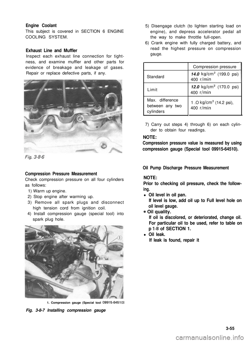
Compression Pressure Measurement
Check compression pressure on all four cylinders
as follows:
1) Warm up engine.
2) Stop engine after warming up.
3) Remove all spark plugs and disconnect
high tension cord from ignition coil.
4) Install compression gauge (special tool) into
spark plug hole.
5) Disengage clutch (to lighten starting load on
engine), and depress accelerator pedal all
the way to make throttle full-open.
6) Crank engine with fully charged battery, and
read the highest pressure on compression
gauge.
Standard
Limit
Max. difference
between any two
cylinders
Compression pressure
14.0 kg/cm2 (199.0 psi)
400 r/min
12.0 kg/cm2 (170.0 psi)
400 r/min
1 .O kg/cm2 (14.2 psi),
400 r/min
3
7) Carry out steps 4) through 6) on each cylin-
der to obtain four readings.
NOTE:
Compression pressure value is measured by using
compression gauge (Special tool 09915-64510).
Oil Pump Discharge Pressure Measurement
NOTE:
Prior to checking oil pressure, check the follow-
ing.
l Oil level in oil pan.
If level is low, add oil up to Full level hole on
oil level gauge.
0 Oil quality.
If oil is discolored, or deteriorated, change oil.
For particular oil to be used, refer to table on
p l-8 of SECTION 1.
l Oil leak.
If leak is found, repair it
1. Compression gauge (Special tool 09915-64510)
Fig. 3-8-7 Installing compression gauge
3-55
Page 134 of 962
16) Clamp wire harness securely.MAINTENANCE SERVICES
Fig. 4- l-39
1. Clamp
17) Remove the pin installed before disassemb-
ly (to lock fast idle cam).
Fig. 4- l-40
Before checking or adjusting the carburetor as
the cause of poor engine performance or rough
idle, check the followings for malconditions.
Ignition system including distributor, timing,
spark plugs and wires.
Air cleaner including thermostatically control-
led air cleaner system.
Evaporative emission control system.
PCV system.
EG R valve.
Engine compression.
Also, check the intake manifold, carburetor and
vacuum hoses for leakage.
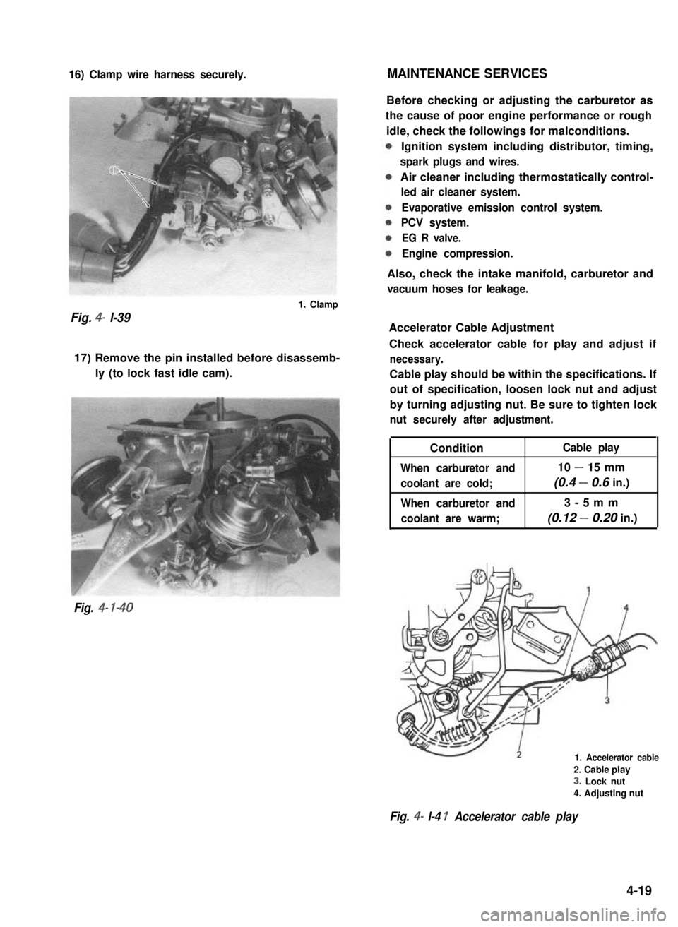
Accelerator Cable Adjustment
Check accelerator cable for play and adjust if
necessary.
Cable play should be within the specifications. If
out of specification, loosen lock nut and adjust
by turning adjusting nut. Be sure to tighten lock
nut securely after adjustment.
Condition
When carburetor and
coolant are cold;
When carburetor and
coolant are warm;
Cable play
10 - 15 mm
(0.4 - 0.6 in.)
3-5mm
(0.12 - 0.20 in.)
1. Accelerator cable
2. Cable play
3. Lock nut
4. Adjusting nut
Fig. 4- l-4 1 Accelerator cable play
4-19
Page 166 of 962

5-2. DIAGNOSIS
POSSIBLE CAUSES OF EMISSIONS TEST FAILURES
Excessive Emission
Hydrocarbons (HC)
ExplanationPossible Causes
Excessive hydrocarbons arel Engine not at normal operating temperature
caused by an air/fuel mixture
that is not burning completely.l Disconnected, obstructed, leaking, or misrouted
vacuum hoses
l Vacuum leaks
.
l Maladjusted idle mixture
l Improper adjusted/sticking choke
l Maladjusted initial spark timing
oDefective spark plugs, wires or distributor cap
l Malfunctioning MCV
lLead contamination of catalytic converter
l Malfunctioning feed back system
Carbon monoxide (CO)Excessive carbon monoxidel Engine not at normal operating temperature
emissions are due to a mixture
that is rich.0 Maladjusted idle mixture
l Improperly adjusted/sticking choke
l Lead contamination of catalytic converter
lLeaking carburetor fuel passages or gaskets
0 Carburetor float level
0 Restricted air cleaner element
l Malfunctioning feed back system
Oxides of nitrogen (Nox)Excessive oxides of nitrogen
are generally due to high tem-
peratures in the combustion
chamber.
l Obstructed/Ieaking/misrouted vacuum lines
0 Improper operation of the EGR system
l Plugged EGR passages
l Inoperative BVSV or TWSV
l Lead contamination of catalytic converter
l Malfunctioning feed back system
5-15
Page 212 of 962
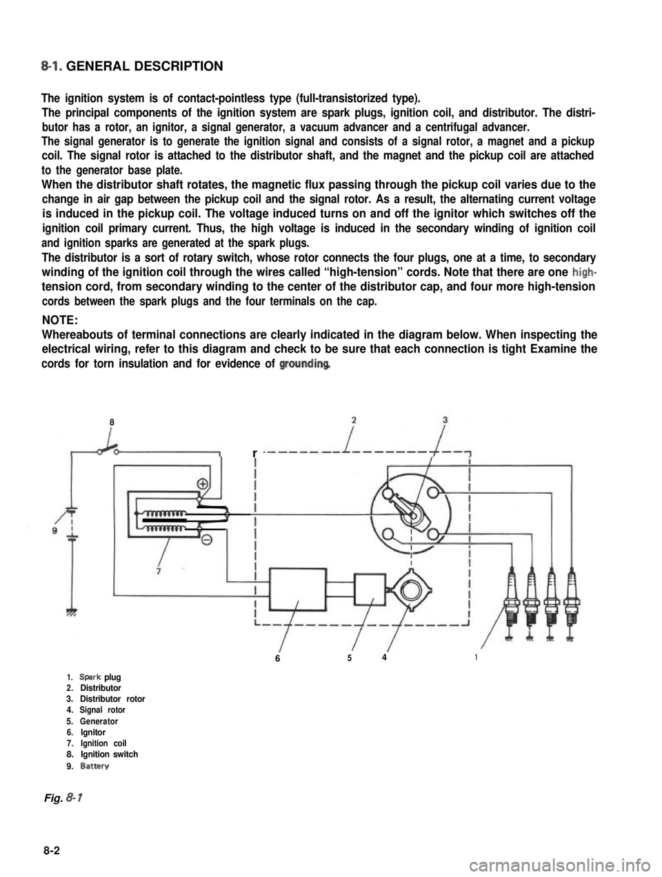
8-l. GENERAL DESCRIPTION
The ignition system is of contact-pointless type (full-transistorized type).
The principal components of the ignition system are spark plugs, ignition coil, and distributor. The distri-
butor has a rotor, an ignitor, a signal generator, a vacuum advancer and a centrifugal advancer.
The signal generator is to generate the ignition signal and consists of a signal rotor, a magnet and a pickup
coil. The signal rotor is attached to the distributor shaft, and the magnet and the pickup coil are attached
to the generator base plate.
When the distributor shaft rotates, the magnetic flux passing through the pickup coil varies due to the
change in air gap between the pickup coil and the signal rotor. As a result, the alternating current voltage
is induced in the pickup coil. The voltage induced turns on and off the ignitor which switches off the
ignition coil primary current. Thus, the high voltage is induced in the secondary winding of ignition coil
and ignition sparks are generated at the spark plugs.
The distributor is a sort of rotary switch, whose rotor connects the four plugs, one at a time, to secondary
winding of the ignition coil through the wires called “high-tension” cords. Note that there are one high-
tension cord, from secondary winding to the center of the distributor cap, and four more high-tension
cords between the spark plugs and the four terminals on the cap.
NOTE:
Whereabouts of terminal connections are clearly indicated in the diagram below. When inspecting the
electrical wiring, refer to this diagram and check to be sure that each connection is tight Examine the
cords for torn insulation and for evidence of groundinq
8
r
6541
1.Spark plug2.Distributor3.Distributor rotor4.Signal rotor
5.Generator6.lgnitor7.Ignition coil8.Ignition switch
9.Battery
Fig. 8- 1
8-2