Page 214 of 962
Ignition Coil
The ignition coil is a sort of miniature transfor-
mer and, as such, has an iron core around which
two coils are wound- primary and secondary
windings mentioned above. The two are so close
to each other that a sudden change in themagnetic flux produced by “primary current”
flowing in primary winding (in a less number of
coil turns) induces a very large electromotive force (voltage) in secondary winding (in a
greater number of coil turns). These live parts
are housed in a tight, insulator case topped by the cap. Note that the cap has three terminals:
one high-tension terminal and two low-tension
terminals.
High-tension terminal
Primary terminal
lt-
Case
It
Primary winding
II
Secondary winding
j- Core
m2 I,,,insulator
Fig. 8-5
Spark Plugs
Each new machine shipped from the factory is
fitted with standard plugs.
Copper core
Center electrode
Fig. 8-6 Insulator
Standard typeCold type
NGKBPRdESBPR-6ES
Nippon DensoWlGEXR-UW’LOEXR-U
8-4
Page 215 of 962

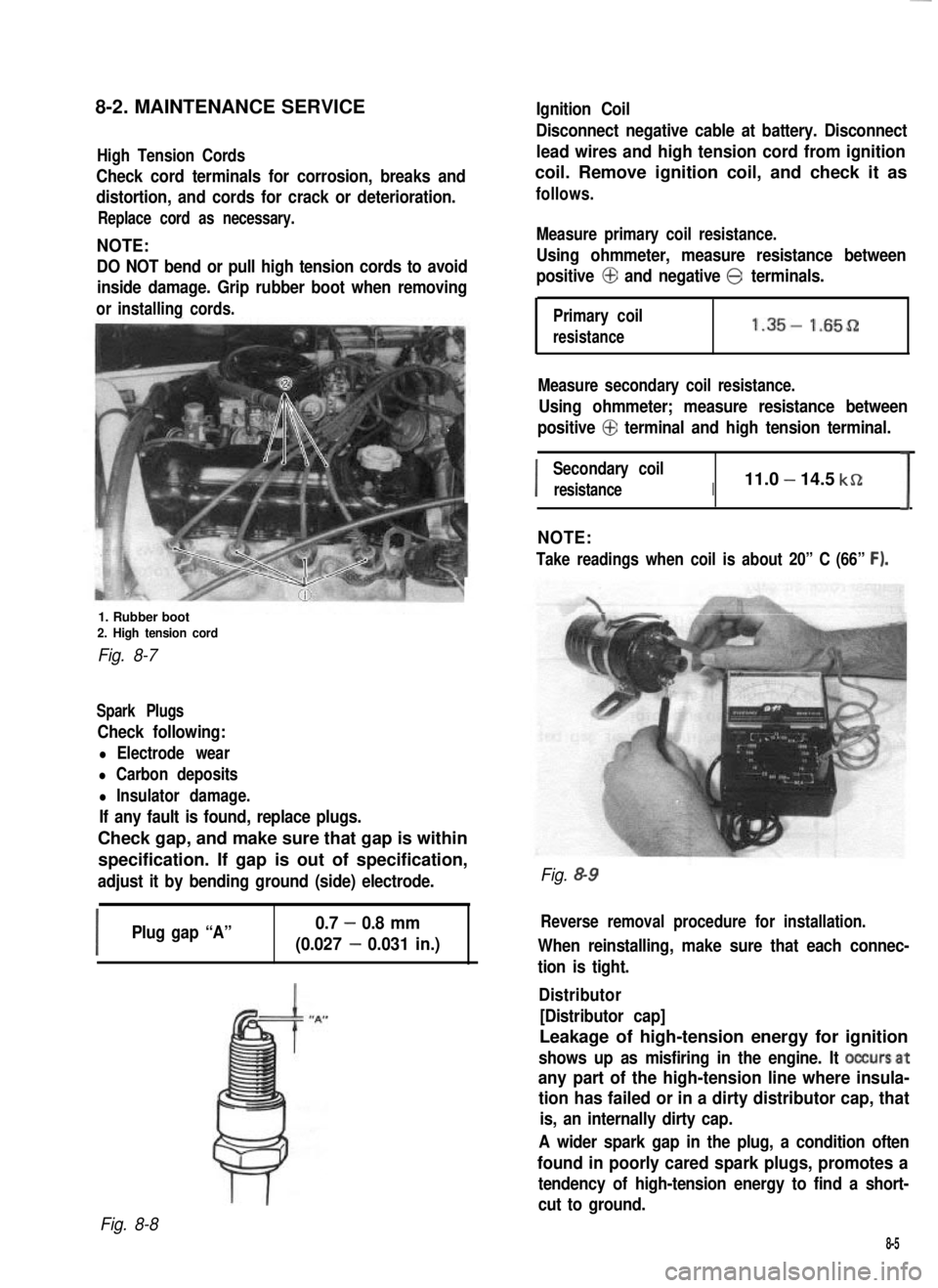
8-2. MAINTENANCE SERVICEIgnition Coil
High Tension Cords
Check cord terminals for corrosion, breaks and
distortion, and cords for crack or deterioration.
Replace cord as necessary.
NOTE:
DO NOT bend or pull high tension cords to avoid
inside damage. Grip rubber boot when removing
orinstalling cords.
1. Rubber boot2. High tension cord
Fig. 8-7
Spark Plugs
Check following:
l Electrode wear
l Carbon deposits
l Insulator damage.
If any fault is found, replace plugs.
Check gap, and make sure that gap is within
specification. If gap is out of specification,
adjust it by bending ground (side) electrode.
I
Plug gap “A”0.7 - 0.8 mm
(0.027 - 0.031 in.)
Disconnect negative cable at battery. Disconnect
lead wires and high tension cord from ignition
coil. Remove ignition coil, and check it as
follows.
Measure primary coil resistance.
Using ohmmeter, measure resistance between
positive @ and negative @ terminals.
Primary coil
resistance1.35- 1.65D
Measure secondary coil resistance.
Using ohmmeter; measure resistance between
positive @ terminal and high tension terminal.
I
Secondary coil
resistanceI11.0 - 14.5 kSZ
I
NOTE:
Take readings when coil is about 20” C (66” F).
Fig. &9
Reverse removal procedure for installation.
When reinstalling, make sure that each connec-
tion is tight.
Distributor
[Distributor cap]
Leakage of high-tension energy for ignition
shows up as misfiring in the engine. It occursat
any part of the high-tension line where insula-
tion has failed or in a dirty distributor cap, that
is, an internally dirty cap.
A wider spark gap in the plug, a condition often
found in poorly cared spark plugs, promotes a
tendency of high-tension energy to find a short-
cut to ground.
Fig. 8-8
8-5
Page 221 of 962

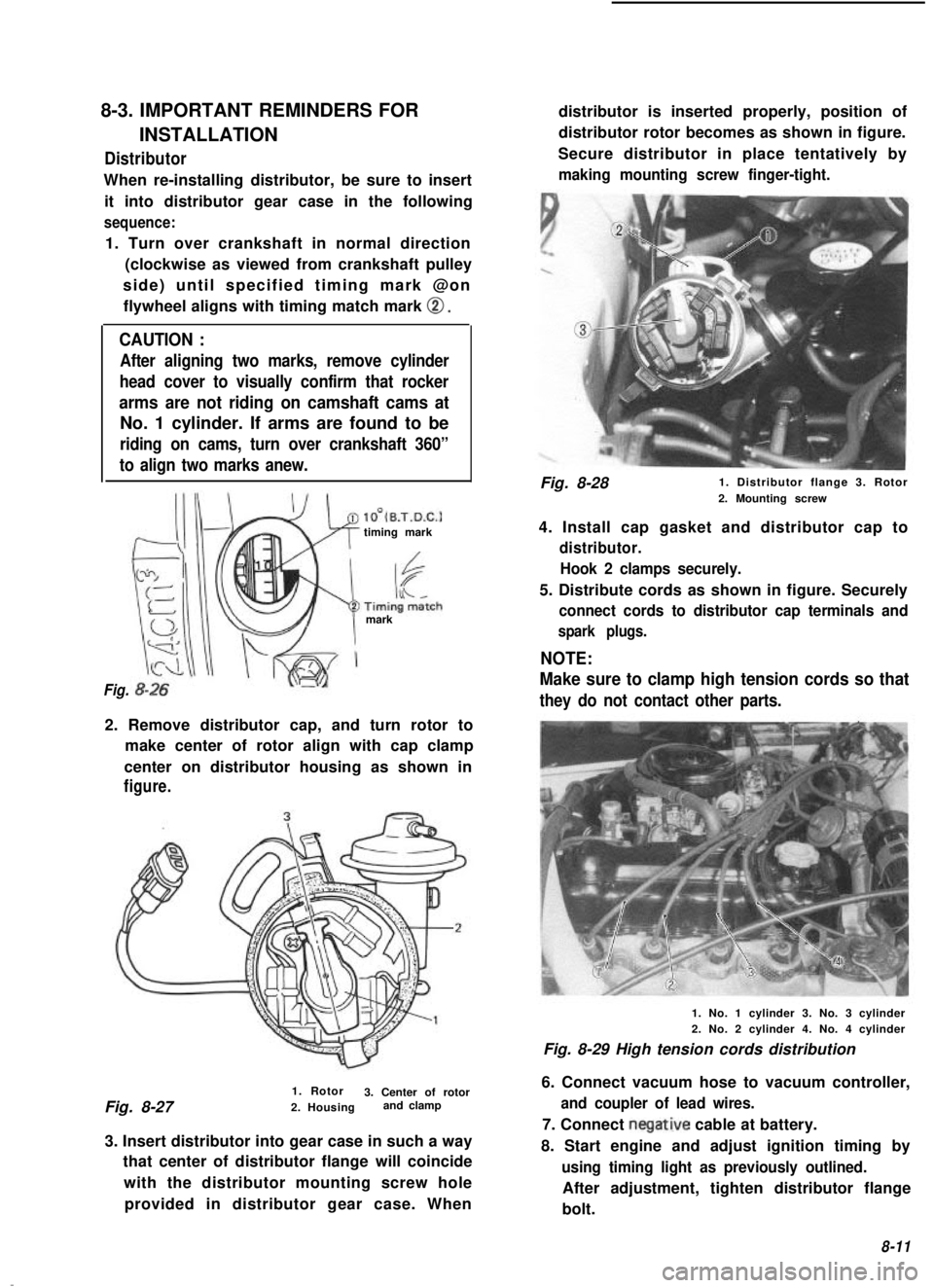
8-3. IMPORTANT REMINDERS FOR
INSTALLATIONDistributor
When re-installing distributor, be sure to insertit into distributor gear case in the following
sequence:
1. Turn over crankshaft in normal direction (clockwise as viewed from crankshaft pulley
side) until specified timing mark @on flywheel aligns with timing match mark
0.
CAUTION :
After aligning two marks, remove cylinder
head cover to visually confirm that rocker
arms are not riding on camshaft cams at
No. 1 cylinder. If arms are found to be
riding on cams, turn over crankshaft 360”
to align two marks anew.
lO’(B.T.D.C.1timing mark
mark
Fig.
2. Remove distributor cap, and turn rotor to make center of rotor align with cap clamp
center on distributor housing as shown in
figure.
1. Rotor
Fig. 8-27 3. Center of rotor
2. Housing and clamp
3. Insert distributor into gear case in such a way that center of distributor flange will coincide
with the distributor mounting screw holeprovided in distributor gear case. When distributor is inserted properly, position of
distributor rotor becomes as shown in figure.
Secure distributor in place tentatively by
making mounting screw finger-tight.
Fig. 8-28 1. Distributor flange 3. Rotor
2. Mounting screw
4. Install cap gasket and distributor cap to
distributor. Hook 2 clamps securely.
5. Distribute cords as shown in figure. Securely
connect cords to distributor cap terminals and
spark plugs.
NOTE:
Make sure to clamp high tension cords so that
they do not contact other parts.
1. No. 1 cylinder 3. No. 3 cylinder
2. No. 2 cylinder 4. No. 4 cylinder
Fig. 8-29 High tension cords distribution
6. Connect vacuum hose to vacuum controller,
and coupler of lead wires.
7. Connect negative cable at battery.
8. Start engine and adjust ignition timing by
using timing light as previously outlined.
After adjustment, tighten distributor flange
bolt.
8-11