Page 265 of 962

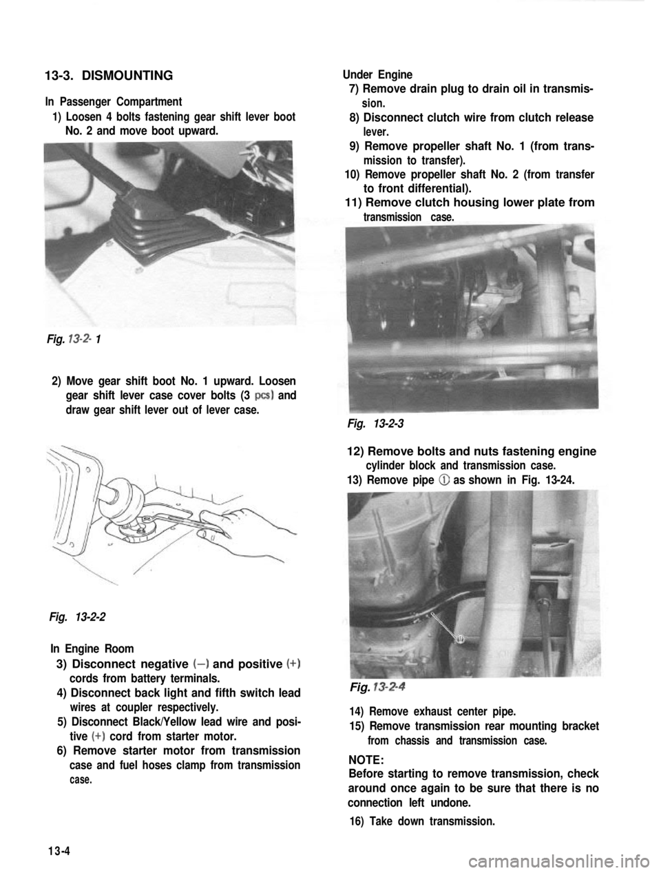
13-3. DISMOUNTINGIn Passenger Compartment
1) Loosen 4 bolts fastening gear shift lever boot
No. 2 and move boot upward.
Fig.
13-2- 1 Under Engine
7) Remove drain plug to drain oil in transmis-
sion.
8) Disconnect clutch wire from clutch release
lever.
9) Remove propeller shaft No. 1 (from trans-
mission to transfer).
10) Remove propeller shaft No. 2 (from transfer
to front differential).
11) Remove clutch housing lower plate from
transmission case.
2) Move gear shift boot No. 1 upward. Loosen
gear shift lever case cover bolts (3
PCS) and
draw gear shift lever out of lever case.
Fig. 13-2-3
Fig. 13-2-2 In Engine Room
3) Disconnect negative (-) and positive (+)
cords from battery terminals.
4) Disconnect back light and fifth switch lead
wires at coupler respectively.
5) Disconnect Black/Yellow lead wire and posi- tive
(+) cord from starter motor.
6) Remove starter motor from transmission
case and fuel hoses clamp from transmission
case.
12) Remove bolts and nuts fastening engine
cylinder block and transmission case.
13) Remove pipe (iJ as shown in Fig. 13-24.
Fig. 13-2-4
14) Remove exhaust center pipe.
15) Remove transmission rear mounting bracket
from chassis and transmission case.
NOTE:
Before starting to remove transmission, check
around once again to be sure that there is no
connection left undone.
16) Take down transmission.
13-4
Page 292 of 962
14-4. TRANSFER SERVICES NOT REQUIRING TRANSFER REMOVAL
Following parts or components do not require transfer removal to receive services (replacement, inspec-
tion) :
Part or ComponentNature of Service
1. Universal-joint yoke flangesReplacement or inspection
2. Front drive shift shaft forkReplacement or inspectionI
3. Transfer output front shaft oil seal
4. Transfer output front shaft bearing
5. Transfer output front shaft
Replacement or inspection
Replacement
Replacement
6. Transfer front caseReplacement
7. Front drive clutch hubReplacement or inspection
8. Front drive clutch sleeveReplacement or inspection
9. Transfer input shaft oil sealReplacement
10. 4WD indicator light switchReplacement or inspection
11. Speedometer driven gearReplacement or inspection
12. Gear shift control leverReplacement or inspection
13. Gear shift control boot No. 1, No. 2Replacement
14. Gear shift control lever spring seatReplacement or inspection.
14-5
Page 293 of 962
14-5. REMOVAL
1) Lift up car and remove securing bolts from
each universal-joint flange connection to
sever 3 propeller shafts from transfer gear
box.
Fig. 14-5
2) Remove clamp @ and boot @ from transfer
gear box.
Fig. 14-7
4) Drain out oil from gear box by loosening
its drainplug.
Fig. 14-8
5) Disconnect speedometer drive cable from
transfer gear box.
Transfer‘gear case
Fig. 14-6
3) Twist control lever guide counterclockwise
while pushing it down; this will permit lever
to be removed from gear box.
14-6
Fig. 14-8
Fig. 14-9
Page 381 of 962

189. MAINTENANCE SERVICES
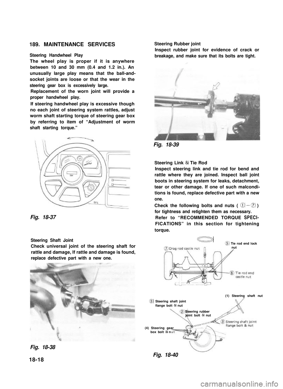
Steering Handwheel Play
The wheel play is proper if it is anywhere
between 10 and 30 mm (0.4 and 1.2 in.). An
unusually large play means that the ball-and-
socket joints are loose or that the wear in the
steering gear box is excessively large.
Replacement of the worn joint will provide a
proper handwheel play.
If steering handwheel play is excessive though
no each joint of steering system rattles, adjust
worm shaft starting torque of steering gear box
by referring to item of “Adjustment of worm
shaft starting torque.”
Fig. 18-37
Steering Shaft Joint
Check universal joint of the steering shaft for
rattle and damage, If rattle and damage is found,
replace defective part with a new one.
0
Steering Rubber joint
Inspect rubber joint for evidence of crack or
breakage, and make sure that its bolts are tight.
Fig. 18-39
Steering Link & Tie Rod
Inspect steering link and tie rod for bend and
rattle where they are joined. Inspect ball joint
boots in steering system for leaks, detachment,
tear or other damage. If one of such malcondi-
tions is found, replace defective part with a new
one.
Check the following bolts and nuts ( @ - 0 )
for tightness and retighten them as necessary.
Refer to “RECOMMENDED TORQUE SPECI-
FICATIONS” in this section for tightening
torque.
a@ Tie rod end locknut
(1) Steering shaft nut
Steering shaft jointflange bolt 84 nut
\,
@ Steering rubberjoint bolt & nut
(4) Steering gearbox bolt & n
Fig. 18-38
Fig. 18-40
18-18
Page 391 of 962
![SUZUKI GRAND VITARA 1987 Service Repair Manual DISC BRAKE CALIPER ASSEMBLY
[GENERAL DESCRIPTION]
This caliper has a single 51.1 mm (2.012 in.) bore and is mounted to the brake caliper holder with two
mounting bolts. Hydraulic force, created by app SUZUKI GRAND VITARA 1987 Service Repair Manual DISC BRAKE CALIPER ASSEMBLY
[GENERAL DESCRIPTION]
This caliper has a single 51.1 mm (2.012 in.) bore and is mounted to the brake caliper holder with two
mounting bolts. Hydraulic force, created by app](/manual-img/20/57437/w960_57437-390.png)
DISC BRAKE CALIPER ASSEMBLY
[GENERAL DESCRIPTION]
This caliper has a single 51.1 mm (2.012 in.) bore and is mounted to the brake caliper holder with two
mounting bolts. Hydraulic force, created by applying force to the brake pedal, is converted by the caliper
to friction. The hydraulic force acts equally against the piston and the bottom of the caliper bore to move
the piston outward and to move (slide) the caliper inward, resulting in a clamping action on the disc. This
clamping action forces the pads (linings) against the disc, creating friction to stop the car.
For details, refer to OPERATION in the next page.
NOTE:
Lubricate parts as specified. Do not use lubricated shop air on brake parts as damage to rubber compo-
nents may result If any component is removed or line disconnected, bleed the brake system. Replace
pads in axle sets only. The torque values specified are for dry, unlubricated fasteners.
1. Caliper guide pin
2. Caliper guide pin sleeve
3. Guide pin boot
4. Guide pin cap
5. Bleeder plug cap
6.Bleeder plug
7. Disc brake caliper(Disc brake cylinder)
8.Piston seal9. Disc brake piston
10.Cylinder boot
11. Disc brake pad12. Disc brake carrier
13. Caliper antirattle clip14.Caliper holder
15.Dust cover16.Brake disc
Fig. 19-5
19-6
Page 396 of 962
![SUZUKI GRAND VITARA 1987 Service Repair Manual BOOSTER ASSEMBLY
[GENERAL DESCRIPTION]
The booster is located between the master cylinder and the brake pedal. It is so designed that the force
created when the brake pedal is depressed is mechanicall SUZUKI GRAND VITARA 1987 Service Repair Manual BOOSTER ASSEMBLY
[GENERAL DESCRIPTION]
The booster is located between the master cylinder and the brake pedal. It is so designed that the force
created when the brake pedal is depressed is mechanicall](/manual-img/20/57437/w960_57437-395.png)
BOOSTER ASSEMBLY
[GENERAL DESCRIPTION]
The booster is located between the master cylinder and the brake pedal. It is so designed that the force
created when the brake pedal is depressed is mechanically increased combined with the engine vacuum.
The booster has a diaphragm of 4 180 mm effective diameter. Its operation is described in the following pages.
NOTE:
Use all components included in repair kits to service this booster. Lubricate rubber parts, where indicat-
ed, with silicone grease provided in kits. The torque values specified are for dry, unlubricated fasteners.
If any hydraulic component is removed or brake line disconnected, bleed the brake system.
Never lubricate any hydraulic component with silicone grease.
11.Vacuum check valve11.No. 2 body oil seal
2.3.Grommet12.Booster air valve assembly
Booster No. 1 body13.Air cleanerseparator
4. PistonRod14.Air cleaner element
5. Reaction disc 15.Body boot
6.Booster piston returnspring16.Nut7. Valve stopper key17.Bracket
8.Booster piston18.Push rod clevis
9. Diaphragm19.Pressure plate
10.Booster No. 2 body
Fig. 19-12
19-11
Page 402 of 962

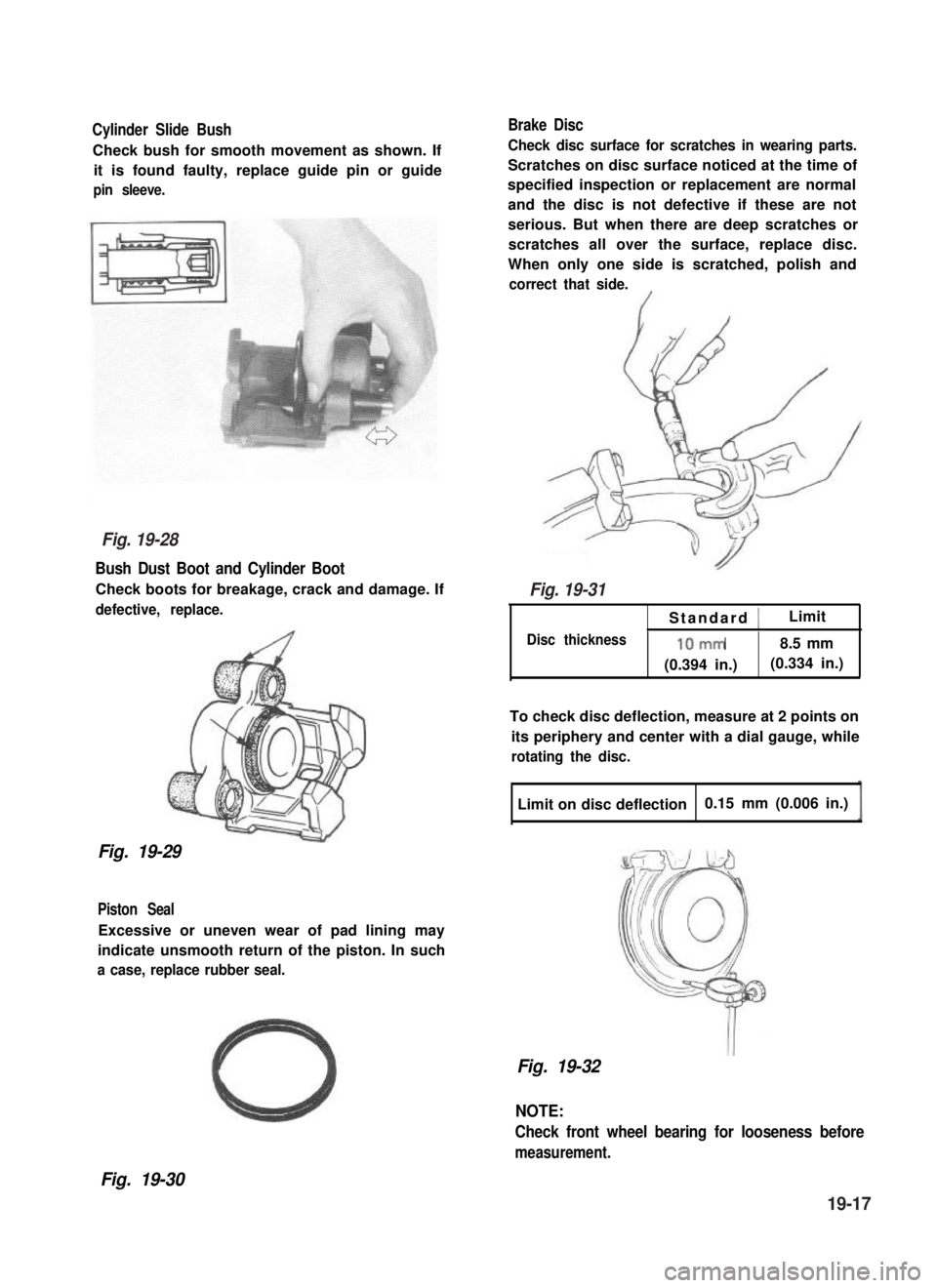
Cylinder Slide Bush
Check bush for smooth movement as shown. If
it is found faulty, replace guide pin or guide
pin sleeve.
Bush Dust Boot and Cylinder Boot
Check boots for breakage, crack and damage. If
defective, replace.
Fig. 19-29
Piston Seal
Excessive or uneven wear of pad lining may
indicate unsmooth return of the piston. In such
a case, replace rubber seal.
Brake Disc
Check disc surface for scratches in wearing parts.
Scratches on disc surface noticed at the time of
specified inspection or replacement are normal
and the disc is not defective if these are not
serious. But when there are deep scratches or
scratches all over the surface, replace disc.
When only one side is scratched, polish and
correct that side.
Standard 1Limit
Disc thickness10mm8.5 mm
(0.394 in.)(0.334 in.)
To check disc deflection, measure at 2 points on
its periphery and center with a dial gauge, while
rotating the disc.
Limit on disc deflection0.15 mm (0.006 in.)
Fig. 19-32
NOTE:
Check front wheel bearing for looseness before
measurement.
Fig. 19-30
Fig. 19-28
Fig. 19-31
19-17
Page 403 of 962

PRECAUTIONS ON INSTALLATION
Reassemble front brake in the reverse order
of disassembly, using care for the following
points.
CAUTION:
Wash each part cleanly before installation
in the same fluid as the one used in
master cylinder reservoir.
Never use other fluid or thinner.
Before installing piston and piston seal
to cylinder, apply fluid to them.
After reassembling brake line, bleed air
from lines.
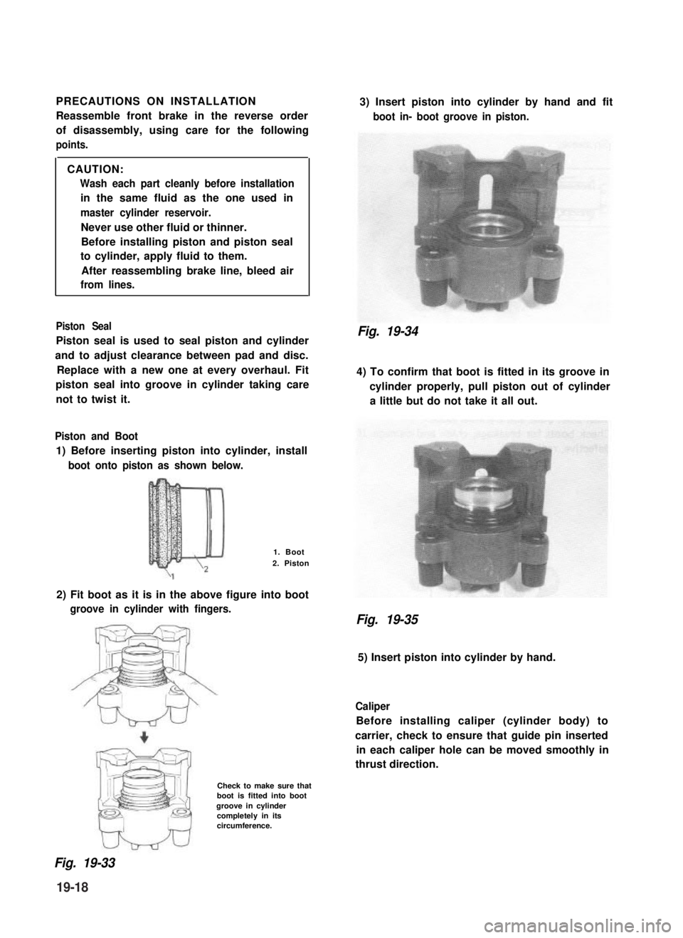
Piston Seal
Piston seal is used to seal piston and cylinder
and to adjust clearance between pad and disc.
Replace with a new one at every overhaul. Fit
piston seal into groove in cylinder taking care
not to twist it.
Piston and Boot
1) Before inserting piston into cylinder, install
boot onto piston as shown below.
1. Boot
2. Piston
2) Fit boot as it is in the above figure into boot
groove in cylinder with fingers.
Check to make sure thatboot is fitted into bootgroove in cylindercompletely in itscircumference.
3) Insert piston into cylinder by hand and fit
boot in- boot groove in piston.
Fig. 19-34
4) To confirm that boot is fitted in its groove in
cylinder properly, pull piston out of cylinder
a little but do not take it all out.
Fig. 19-35
5) Insert piston into cylinder by hand.
Caliper
Before installing caliper (cylinder body) to
carrier, check to ensure that guide pin inserted
in each caliper hole can be moved smoothly in
thrust direction.
Fig. 19-33
19-18